Table of Contents
Advertisement
Quick Links
MANUAL
FOR CONTROLLER
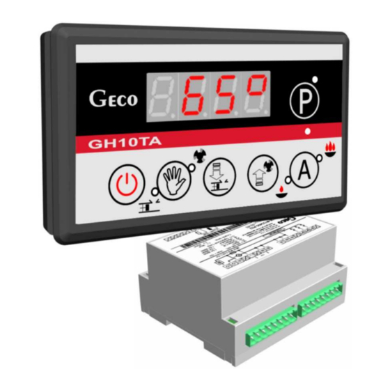
GH10TA
FOR CONTROLLING
CENTRAL HEATING BOILERS
WITH PISTON FEEDER
Program version: 03a
USER MANUAL
We request that users carefully study applicable Instructions before connecting and
starting up any of our products.
Should any doubts arise, please contact our Company between 8 a.m. and 4 p.m.
Attention !!! At the bottom of each page you will find last document's update date. Please, always use the
most recent version of the Instructions, which is available free of charge and will be mailed to you if ordered.
Advertisement
Table of Contents

Related Manuals for Geco GH10TA


Summary of Contents for Geco GH10TA
- Page 1 MANUAL FOR CONTROLLER GH10TA FOR CONTROLLING CENTRAL HEATING BOILERS WITH PISTON FEEDER Program version: 03a USER MANUAL We request that users carefully study applicable Instructions before connecting and starting up any of our products. Should any doubts arise, please contact our Company between 8 a.m. and 4 p.m.
-
Page 2: Table Of Contents
RIORITY 8.4..........................17 UMMER ROOM THERMOSTAT ........................17 TEMPERATURE LIMITER (STB) ...................... 18 CONNECTION DEVICES TO THE GH10TA CONTROLLER ..............18 INFORMATION ON LABELLING AND COLLECTION OF WORN OUT ELECTRICAL AND ELECTRONIC EQUIPMENT ..........................19 Issue I July 2017... -
Page 3: Introduction
GH10TA USER MANUAL PAGE 3 INTRODUCTION 1.1. Graphic symbols Symbols intended to indicate and at the same time emphasise the importance of text containing information that warns against dangerous situation have the following graphic forms: Warning This symbol is used when it is necessary in described instructions to follow the sequence of carried out operations. -
Page 4: Keyboard And Function Keys
GH10TA USER MANUAL PAGE 4 1.2. Keyboard and Function Keys AUTO-OPERATION INDICATOR AUTO MAINTAIN OPERATION INDICATOR ON/OFF MANUAL MANUAL FAN AND CH PUMP CONTROL ACTIVATION / INCREASE MANUAL FEEDER AND DHW PUMP ACTIVATION / DECREASE PARAMETER PARAMETER VALUE VALUE USER CAN TURN OFF AND TURN ON CONTROLLER BY USING BUTTON ACTIVATE ALL BUTTON ON PANEL TOUCH KEYBORD TAKES PLACE AFTER TOUCH EACH OF THEM AND HOLD FOR MOMENTS. -
Page 5: General Features
GH10TA USER MANUAL PAGE 5 GENERAL FEATURES The GH10TA Controller is a microprocessor-based device manufactured using the Surface Mount Technology (SMT). It is designed to control the processes of Hot Utility Water (HUW) heating and the main Central Heating (CH) water circuit. Control parameters can be adjusted to the current operating conditions and boiler type. -
Page 6: Technical Data
GH10TA USER MANUAL PAGE 6 TECHNICAL DATA Power supply 230V AC +10% -15% NTC sensor resistance characteristics Operating temperature range +5°C to +40°C Humidity 20% to 80% RH Temperature Resistance 7174.89 Fan protection 3.15A 4374.83 Sensor type NTC 2.2kΩ 2747.10 Sensor operating temperature 0°C÷100°C... -
Page 7: Quick Start
GH10TA USER MANUAL PAGE 7 QUICK START To quickly start the GH10TA Controller, perform the following actions: 1. Touch keyboard calibration. After connecting the controller to the power supply, the controller for about 4 seconds calibrates the touch keyboard. During calibration you can not bring your hands to the sensors, because it would cause incorrect calibration, and consequently malfunction of the keyboard. - Page 8 GH10TA USER MANUAL PAGE 8 4. Press . Screen appears: and the Controller starts automatic operation according to the factory settings. Table 1 Factory settings table Nastawa Parametr Opis parametru Krok fabryczna Boiler temperature setting ’F03’ ’F04’ 1°C 60°C Feeder standstill duration...
-
Page 9: The Gh10Ta Operation
GH10TA USER MANUAL PAGE 9 THE GH10TA OPERATION 6.1. Operated Heating System 6.1.1. Central Heating cycle + HUW cycle INPUTS OUTPUTS T1 – Boiler temp. P1 – Fuel feeder T2 – Feeder temp. P2 – Fan T3 – HUW temp. -
Page 10: Automatic Operation Mode
GH10TA USER MANUAL PAGE 10 6.2. Automatic operation mode. By pressing , you can turn on the automatic operation mode – the Controller lights the upper indicator 6.2.1. Fuel Feeder In the AUTO mode, the fuel feeder operates according to the value set in the user settings U1 –... -
Page 11: Manual Operation Mode
GH10TA USER MANUAL PAGE 11 6.2.5. Reed relay In AUTO mode the feeder sensor (reed relay) works according to the value set in F19 and F22 service parameters. After exceeding the time of (5/4 x (F19xF22)) and no reed relay activation the AL9 alarm will appear (⇒... -
Page 12: Alarm Conditions
GH10TA USER MANUAL PAGE 12 6.5. Alarm Conditions The Controller uses 8 different alarm conditions. In each alarm condition, the Controller displays the alarm number and activates the alarm sound output. In case of several alarm conditions occurring simultaneously, their numbers are displayed in sequence. You can exit an alarm condition only by pressing . -
Page 13: Boiler Burnout Detection
If NOT, this means that the furnace is burned out – the Controller enters the AL13 alarm condition. 6.8. Maximum Feeder Temperature Detection The GH10TA Controller is equipped with an additional option of protecting from temperature rise in the fuel feeder above the permissible value to prevent backfires into the fuel feeder. -
Page 14: User Settings
GH10TA SERVICE MANUAL STRONA 14 USER SETTINGS 7.1. Boiler Temperature Setting (U0) You can change the boiler temperature setting using the following procedure: STEP 1 STEP 2 STEP 3 → → Green LED lights on the Set a new desired Save the new key. -
Page 15: Fan Speed (U3)
7.1 and 7.2. Settings are within the range of 35°C to 65°C. 7.6. Anti-Legionella Function (U5) The GH10TA controller is equipment in Anti-Legionella function which limit growth Legionella pneumophilia bacterium on HUW installation. This function is available for users when value F00 service parameter was adjust on „02”, „03”... -
Page 16: Instalation And Connections
GH10TA USER MANUAL PAGE 16 The GH10TA Controller allows connection of an additional pump to control the Hot Utility Water (HUW) in the boiler. 8.1. Instalation and Connections To use the Hot Utility Water (HUW) heating option, perform the following actions: connect the boiler according to the enclosed diagram (⇒... -
Page 17: Huw Priority
04 – HUW pump summer mode 8.3. HUW Priority The GH10TA Controller allows to set operation of the HUW pump with priority. If you choose this mode of HUW pump operation, the hot utility water heating is a higher priority function in the Controller. -
Page 18: Temperature Limiter (Stb)
GH10TA USER MANUAL PAGE 18 10. TEMPERATURE LIMITER (STB) The GH10TA Controller can be equipped with an additional independent temperature limiter STB via terminals 15 and 16. WHEN THE TEMPERATURE LIMITER IS NOT USED, TERMINALS 15 AND 16 SHOULD BE SHORTED. -
Page 19: Information On Labelling And Collection Of Worn Out Electrical And Electronic Equipment
GH10TA USER MANUAL PAGE 19 Fig. 1 Diagram of connection outputs and inputs devices and temperature sensor in the GH10TA controller. ANY ADDITIONAL EQUIPMENT MAY BE CONNECTED TO THE GH10TA CONTROLLER ONLY BY PERSON LICENSED TO PERFORM ELECTRICAL INSTALLATION WORKS. - Page 20 P.P.U.H. „Geco” Sp. z o.o. Cholerzyn 376, 32-060 Liszki, Poland ph. 012/636-98-11, 636-12-90 fax. 012/636-20-02 http://www.geco.pl e-mail: geco@geco.pl...
Need help?
Do you have a question about the GH10TA and is the answer not in the manual?
Questions and answers