
Related Manuals for voestalpine bohler WF 4000 Classic


Summary of Contents for voestalpine bohler WF 4000 Classic
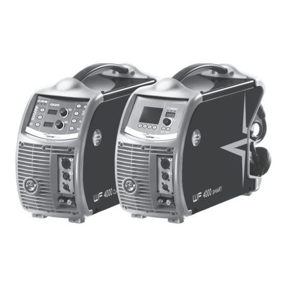
- Page 1 Lasting Connections WF 4000 CLASSIC-SMART INSTRUCTION MANUAL voestalpine Böhler Welding www.voestalpine.com/welding...
- Page 2 Cod. 91.08.343 Data 12/06/2019 Rev. ENGLISH 9 Rating plate 10 Meaning rating plate 11 Diagram 12 Connettori 13 Spare parts list 14 Installation kit/accessories...
- Page 3 ENGLISH CE - DECLARATION OF CONFORMITY Company SELCO s.r.l. - Via Palladio, 19 - 35019 ONARA DI TOMBOLO (Padova) - ITALY Tel. +39 049 9413111 - Fax +39 049 9413311 - E-mail: selco@selcoweld.com - www.selcoweld.com WF 4000 Classic hereby declares that the equipment: WF 4000 Smart conforms to the EU directives: 2014/35/EU...
-
Page 4: Table Of Contents
INDEX 1 WARNING ..............................35 1.1 Work environment ..........................35 1.2 User's and other persons' protection..................... 35 1.3 Protection against fumes and gases ...................... 36 1.4 Fire/explosion prevention ........................36 1.5 Prevention when using gas cylinders ....................36 1.6 Protection from electrical shock ......................36 1.7 Electromagnetic fields &... -
Page 5: Warning
1 WARNING Always use regulation shoes that are strong and ensure insulation from water. Before performing any operation on the machine, make sure that you have thoroughly read and understood the contents of this booklet. Always use regulation gloves ensuring electrical and Do not perform modifications or maintenance thermal insulation. -
Page 6: Protection Against Fumes And Gases
• When you finish welding, check that the live circuit cannot Keep a first aid kit ready for use. accidentally come in contact with any parts connected to the Do not underestimate any burning or injury. earth circuit. • Position a fire-fighting device or material near the work area. Before leaving work, make the area safe, in order 1.5 Prevention when using gas cylinders to avoid accidental damage to people or property. -
Page 7: Electromagnetic Fields & Interferences
1.7 Electromagnetic fields & Welding cables interferences To minimise the effects of electromagnetic fields follow the fol- lowing instructions: - Where possible, collect and secure the earth and power cables together. • The welding current passing through the internal and external - Never coil the welding cables around your body. -
Page 8: Lifting, Transport & Unloading
2.1 Lifting, transport & unloading 2.4 Installation - The equipment is provided with a handle for hand transportation. Connection for MMA welding - The equipment is not equipped with specific lifting elements. The connection shown in the figure produces Use a fork lift truck paying attention during operations in reverse polarity welding. -
Page 9: System Presentation
3 SYSTEM PRESENTATION 3.1 General The wire feed unit WF 4000 is the mobile part of a complete MIG/MAG welding system which uses the URANOS 3200 GSM, PME, MSE generators. It is connected to the generator by a bundle of cables of variable length. - Page 10 Main adjustment handle STANDARD MIG/MAG Allows the regulation of the arc voltage. Ø (mm) Allows regulation of the arc length during welding. Manual MIG/MAG G3/4 Si1 CO 2 S 5* High voltage = long arc G3/4 Si1 Ar 18%CO 2 S 10* Low voltage = short arc CrNi 19 9 Ar 2%CO 2...
-
Page 11: Front Control Panel (Wf 4000 Smart)
3.3 Front control panel (WF 4000 Smart) 3.4 Starting Screen (WF 4000 Smart) When switched on, the generator performs a succession of checks in order to guarantee the correct operation of the system and of all the devices connected to it. At this stage the gas test is also carried out to check the proper connection to the gas supply system (system for automation and robotics). -
Page 12: Main Screen (Wf 4000 Smart)
3.6 Main Screen (WF 4000 Smart) - The synergic curve selected 1a Type of filler metal Allows the control of the system and of the welding process, 1b Wire diameter showing the main settings. 1c Type of gas - Welding parameters 1d Welding current 1e Part thickness 1f Corner bead... -
Page 13: Set Up (Wf 4000 Smart)
Measurements TIG DC During the welding operation, the real current and volt- Allows the selection of the welding method age measurements are shown on the LCD display. 2 Step 4 Step Bilevel MIG/MAG - Pulsed MIG Allows the selection of the welding method 2 Step 4 Step 5a Welding current... - Page 14 Arc force Buzzer tone Allows adjustment of the Arc force value in MMA. Permits adjustment of the buzzer tone. Permits an adjustable energetic dynamic response in Minimum Off, Maximum 10, Default 10 welding, facilitating the welder's operations. Adjustment step Parameter set as a percentage (%) of the welding current. Permits adjustment of the variation step on the up- Minimum Off, Maximum 500%, Default 30% down keys.
- Page 15 Voltage reading Pulsed frequency Allows the real value of the welding voltage to be dis- Allows activation of the pulse mode. played. Allows regulation of the pulse frequency. Allows the welding voltage display method to be set Allows better results to be obtained in the welding of (consult the “Interface personalisation”...
- Page 16 Allows the selection of the required graphic interface: Corner bead XE (Easy Mode) Lets you set bead depth in a corner joint. XA (Advanced Mode) XP (Professional Mode) Arc length Allows regulation of the arc length during welding. Allows access to the higher set-up levels: Minimum -5.0, Maximum +5.0, Default syn USER: user Pre-gas...
-
Page 17: Synergic Curves Screen (Wf 4000 Smart)
Initial increment time Circuit resistance calibration Lets you set the initial increment time. Lets you auto- Lets you calibrate the system. mate the “crater filler” function. Press the encoder knob to access parameter 705. Minimum 0.1s, Maximum 99.9s, Default Off Place the tip of the wire guide in electrical contact with Crater filler time the work piece. -
Page 18: Programs Screen
3.9 Programs screen Select however one of suggested synergies (5-6) in order to take advantage of ignition potentiality, General closing arc features…. Allows the storage and management of 64 welding pro- grams which can be personalised by the operator. Lets you select: - type of filler material - gas type Lets you select:... - Page 19 Program cancellation Introduce a description of the program (7). Select the required program by rotating the encoder. - Select the required letter by rotating the encoder. Delete the selected program by pressing button (1) - Store the selected letter by pressing the encoder. - Cancel the last letter by pressing button (1) Confirm the operation by pressing button (2) Cancel the operation by pressing button (2)
-
Page 20: Interface Personalisation (Wf 4000 Smart)
3.10 Interface personalisation 3.11 Lock/unlock (WF 4000 Smart) (WF 4000 Smart) Allows the parameters to be customized on the main menu. Allows all the settings to be locked from the control panel with a security password. Allows the selection of the required graphic interface: XE (Easy Mode) Enter set-up by pressing the encoder key for at least 5 seconds. -
Page 21: External Controls Management (Wf 4000 Smart)
3.12 External controls management (WF 4000 Smart) Allows the setting of the welding parameters management method by the external devices (RC, torch…). Enter the “Guard limits” screen by pressing the encoder button. Select the required parameter by pressing button (1) Select the method of setting the guard limits by pressing button Enter set-up by pressing the encoder key for at least 5 seconds. -
Page 22: Alarms Screen
3.14 Alarms screen Incompatible measurements alarm Allows the intervention of an alarm to be indicated and provides the most important indications for the solution of any problem Communication alarm (HF) encountered. Undervoltage alarm E39, E40 System power supply alarm Coolant shortage alarm Alarm icon Wire out alarm Alarm code... -
Page 23: Rear Panel
4 ACCESSORIES Speed limit exceeded (Warning) 4.1 General Operation of the remote control is activated when connected Speed limit exceeded (Alarm) to the power sources. This connection can be made also with the system power on. With the RC control connected, the power source control panel Speed limit exceeded (Warning) stays enabled to perform any modification. -
Page 24: Mig/Mag Series Torches
4.5 MIG/MAG series torches 4.10 Feed unit wheels - upgrade kit (73.10.074) "Consult the “Installation kit/accessories” section". 4.11 Wire feeder holder kit (73.10.075) "Consult the “Installation kit/accessories” section". 5 MAINTENANCE Routine maintenance must be carried out on the system according to the manufacturer’s instruc- tions. - Page 25 The system fails to come on (green LED off) Cause Mains voltage out of range Cause No mains voltage at the socket. Solution Connect the system correctly. Read the paragraph "Connections ". Solution Check and repair the electrical system as needed. Use qualified personnel only.
- Page 26 Arc instability Cause Incorrect welding mode. Solution Decrease the distance between the electrode and Cause Insufficient shielding gas. Solution Adjust the gas flow. the piece. Check that the diffuser and the gas nozzle of the Move regularly during all the welding operations. torch are in good condition.
-
Page 27: Welding Theory
7 WELDING THEORY Porosity Cause Grease, varnish, rust or dirt on the workpieces to be welded. 7.1 Manual Metal Arc welding (MMA) Solution Clean the workpieces carefully before welding. Preparing the edges To obtain good welding joints it is advisable to work on clean Cause Grease, varnish, rust or dirt on the filler material. -
Page 28: Tig Welding (Continuos Arc)
Removing the slag D.C.S.P.-Pulsed (Direct Current Straight Polarity Pulsed) Welding using covered electrodes requires the removal of the The use of pulsed direct current allows better control, in particu- slag after each run. lar operating conditions, of the welding pool width and depth. The slag is removed by a small hammer or is brushed away if The welding pool is formed by the peak pulses (Ip), while the friable. -
Page 29: Copper Tig Welding
7.2.2 Copper TIG welding Welding parameters The visibility of the arc reduces the need for the user to strictly Since TIG welding is a process characterized by high heat con- observe the adjustment tables as he can directly monitor the centration, it is particularly suitable for welding materials with weld pool. - Page 30 SELECTION GUIDE OF WELDING PARAMETERS WITH REFERENCE TO THE MOST TYPICAL APPLICATIONS AND MOST COMMONLY USED WIRES Wire diameter - weight per metre Voltage arc (v) 0,8 mm 1,0-1,2 mm 1,6 mm 2,4 mm Low penetration for thin Good penetration and Good flat and vertical Not used materials...
-
Page 31: Technical Specifications
8 TECHNICAL SPECIFICATIONS WF 4000 Classic WF 4000 Smart Wire feeder SL4R-2T(v.2R) SL4R-2T(v.2R) Wire feeder rated power 120W 120W No rolls 2 (4) 2 (4) Wire diameter / Standard roller 1.0-1.2 mm 1.0-1.2 mm Wire diameters / 0.6-1.6 mm solid wire 0.6-1.6 mm solid wire Tractable rollers 0.8-1.6 mm aluminium wire 0.8-1.6 mm aluminium wire... - Page 32 9 Targa dati, Rating plate, Leistungschilder, Plaque données, Placa de características, Placa de dados, Technische gegevens, Märkplåt, Dataskilt, Identifikasjonsplate, Arvokilpi, πινακιδα χαρακτηριστικων European product Do not dispose of electrical equipment together with normal waste! In observance of European Directive 2002/96/EC on Waste Electrical and Electronic Equipment and its implementation in accordance with national law, electrical equipment that has reached the end of its life must be col- lected separately and returned to an environmentally compatible recycling...
- Page 33 10 Meaning rating plate ENGLISH Trademark Name and address of manufacturer Machine model Serial no. Reference to construction standards Intermittent cycle symbol Rated welding current symbol 6A/6B Intermittent cycle values 7A/7B Rated welding current values Power supply symbol Rated power supply voltage Maximum rated power supply current Protection rating...
- Page 34 11 Diagram...
- Page 35 12 Connectors...
- Page 36 13 Spare parts list WF 4000 Classic 71.01.062 WF 4000 Smart 71.01.060...
- Page 38 SL 4R-2T (v.2R) 07.01.339...
- Page 40 14 Installation kit/accessories Cable bundle...
- Page 41 2X M6 M6x30mm...
- Page 42 73.11.012 Kit Push-Pull...
- Page 43 M3,5x9mm...
- Page 44 73.10.073 Feed unit wheels - upgrade kit M8x14mm 16X M8 D20mm/d5,5mm M5x20mm M5x25mm...
- Page 45 73.10.074 Feed unit wheels - upgrade kit M5x10mm 16X M5 M5x10mm...
- Page 46 73.10.075 Wire feeder holder kit 4X M6 M6x20mm...
- Page 47 Böhler Welding www.voestalpine.com/welding...
Need help?
Do you have a question about the bohler WF 4000 Classic and is the answer not in the manual?
Questions and answers