
Related Manuals for EDA ED-IPC2600 Series


Summary of Contents for EDA ED-IPC2600 Series
- Page 1 ED-IPC2600 Series High Reliability Industrial Computer Based On Raspberry Pi User Manual EDA Technology Co., LTD December 2023...
- Page 2 IOT, industrial control, automation, green energy and artificial intelligence based on Raspberry Pi technology platform. You can contact us in the following ways: EDA Technology Co.,LTD Address:Room 301, Building 24, No.1661 Jialuo Road, Jiading District, Shanghai Mail: sales@edatec.cn...
- Page 3 Copyright Statement ED-IPC2600 series and its related intellectual property rights are owned by EDA Technology Co.,LTD. EDA Technology Co.,LTD owns the copyright of this document and reserves all rights. Without the written permission of EDA Technology Co.,LTD, no part of...
- Page 4 EDA Technology Co.,LTD does not guarantee that the information in this manual is up to date, correct, complete or of high quality. EDA Technology Co.,LTD also does not guarantee the further use of this information. If the material or non-...
-
Page 5: Reader Scope
This document introduces the appearance, installation, startup ED-IPC2600 Series User Manual and configuration of ED-IPC2600 series to help users use the product better. This document introduces the OS download, eMMC flashing and ED-IPC2600 Series Application Guide partial configuration of ED-IPC2600 series to help users use the product better. -
Page 6: Symbolic Convention
Related Agreement Terminology Convention Terminology Meaning Raspberry Pi Compute Module 4 Symbolic Convention Symbolic Instruction Prompt symbols, indicating important features or operations. Notice symbols, which may cause personal injury, system damage, or signal interruption/loss. May cause great harm to people. -
Page 7: Safety Instructions
Safety Instructions This product should be used in an environment that meets the requirements of design specifications, otherwise it may cause failure, and functional abnormality or component damage caused by non-compliance with relevant regulations are not within the product quality assurance scope. ... -
Page 8: Table Of Contents
Content Foreword ..............................i Related Manuals ..........................i Reader Scope ............................i Related Agreement ..........................ii Terminology Convention ....................... ii Symbolic Convention ........................ii Safety Instructions ............................. iii Product Description ......................... 1-1 Overview ........................... 1-2 Packing List ........................1-3 Appearance ........................1-4 1.3.1 Front Panel ........................ - Page 9 Finding Device IP ......................5-2 5.1.1 Query IP by Using ifconfig Command ................ 5-2 5.1.2 Login Router to Query IP ................... 5-2 5.1.3 Scan For Using NMAP Tool ..................5-3 Remote Login ........................5-5 5.2.1 Connect To The Device Via SSH ................5-5 5.2.2 Connect To The Device Desktop Through VNC ............
-
Page 10: Product Description
1 Product Description 1 Product Description This chapter introduces the product overview, packing list, appearance, button, indicators and interfaces. Overview Packing List Appearance Button Indicator Interface ED-IPC2600 Series User Manual... -
Page 11: Overview
1 Product Description 1.1 Overview ED-IPC2600 series is a highly reliable industrial computer based on Raspberry Pi CM4. According to different application scenarios and user needs, different specifications of RAM and eMMC computer systems can be selected. RAM can choose 1GB、2GB、4GB and 8GB ... -
Page 12: Packing List
1 Product Description 1.2 Packing List 1x ED-IPC2600 Unit (with DIN-rail bracket) [option Wi-Fi/BT version] 1x 2.4GHz/5GHz Wi-Fi/BT Antenna [option 4G version] 1x 4G/LTE Antenna ED-IPC2600 Series User Manual... -
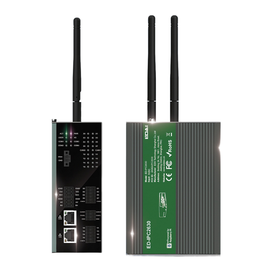
Page 13: Appearance
8 x green DI indicators, which is used to check the communication status of DI signal. 8 x green DO indicators, which is used to check the communication status of DO signal. 8 x DI ports, 10-Pin 3.5mm spacing phoenix terminals, which is used to connect third- ED-IPC2600 Series User Manual... - Page 14 1 x green user indicator, user can customize a status according to actual application. 1 x green system status indicator, which is used to check the working status of device. 1 x red power indicator, which is used to check the status of device power-on and power-off. ED-IPC2600 Series User Manual...
- Page 15 2 x RS232 ports, 6-Pin 3.5mm spacing phoenix terminal, which is used to connect the third-party control equipment. 1 x DC input, 2-Pin 3.5mm spacing phoenix terminals with screw holes. It supports 9V~36V input, the signal is defined as VIN+/GND. ED-IPC2630 ED-IPC2600 Series User Manual...
-
Page 16: Rear Panel
1 x DC input, 2-Pin 3.5mm spacing phoenix terminals with screw holes. It supports 9V~36V input, the signal is defined as VIN+/GND. 1.3.2 Rear Panel Introducing the types and definitions of the rear panel interface. ED-IPC2600 Series User Manual... -
Page 17: Side Panel
1 x Nano SIM slot, uses to install a SIM card for acquiring 4G signals. 1 x Micro USB port, it supports to flash eMMC for the system. 1.3.3 Side Panel Introducing the types and definitions of side panel interfaces. ED-IPC2600 Series User Manual... - Page 18 1 x HDMI port, type A connector, which compatibles with HDMI2.1 standard and supports 4K 60Hz. It supports to connect a displayer. 1 x Wi-Fi/BT antenna port(optional), SMA connector, which can connect to Wi-Fi/BT antenna. 1 x 4G antenna port(optional), SMA connector, which can connect to 4G antenna. ED-IPC2600 Series User Manual...
-
Page 19: Button
1 Product Description 1.4 Button ED-IPC2600 series device includes a RESET button, which is a hidden button, and the silkscreen on the case is "RESET". Pressing the RESET button will reset the device. ED-IPC2600 Series User Manual 1-10... -
Page 20: Indicator
1 Product Description 1.5 Indicator Introducing the various statuses and meanings of indicators contained in ED-IPC2600 series device. Indicator Status Description The device has been powered on. Power supply of the device is abnormal, please stop the power supply Blink immediately. -
Page 21: Interface
Introducing the definition and function of each interface in the product. 1.6.1 Card Slot ED-IPC2600 series device includes an SD card slot and a Nano SIM card slot. 1.6.1.1 SD Card Slot The silkscreen on the case of Micro SD card slot is " ", which is used to install SD card for storing user data. -
Page 22: Rs485 Interface
1 Product Description Pin ID Pin Name 9V~36V 1.6.3 RS485 Interface ED-IPC2600 series equipment includes 2 RS485 ports, 6-Pin 3.5mm spacing phoenix terminals . The silkscreen of single RS485 is "IGND/A/B". Pin Definition Terminal pins are defined as follows: Pin ID... -
Page 23: Rs232 Interface
Corresponding COM port the corresponding COM COM2 COM4 1.6.4 RS232 Interface ED-IPC2600 contains 2 RS232 ports, 6-Pin 3.5mm spacing phoenix terminals . The silkscreen of single RS232 is "IGND/TX/RX". Pin Definition Terminal pins are defined as follows: ED-IPC2600 Series User Manual 1-14... -
Page 24: Di Interface
ED-IPC2610: 8 x DI ED-IPC2620: 4 x DI ED-IPC2630: 8 x DI Every 4 DI share one common pin (called COM): X0, X2, X4 and X6 share COMX0; X1, X3, X5 and X7 share COMX1. ED-IPC2600 Series User Manual 1-15... - Page 25 Terminal pins are defined as follows: Pin ID Pin Name COMX0 COMX1 Pin Definition -ED-IPC2620 Terminal pins are defined as follows: Pin ID Pin Name COMX0 Connecting Cables Schematic diagram of a single DI wire is as follows: ED-IPC2600 Series User Manual 1-16...
-
Page 26: Do Interface
ED-IPC2630: 8 x DO Every 4 DO share one common pin (called COM): Y0, Y2, Y4 and Y6 share COMY0; Y1, Y3, Y5 and Y7 share COMY1. Pin Definition -ED-IPC2610&ED-IPC2630 Terminal pins are defined as follows: ED-IPC2600 Series User Manual 1-17... - Page 27 1 Product Description Pin ID Pin Name COMY0 COMY1 Pin Definition -ED-IPC2620 Terminal pins are defined as follows: Pin ID Pin Name COMY0 ED-IPC2600 Series User Manual 1-18...
-
Page 28: Can Interface
5~30 VDC (24 VDC is recommended), maximum current is 1.5A (per channel) 1.6.7 CAN Interface ED-IPC2600 contains 0 ~ 2 CAN ports. Different product models correspond to different numbers of CAN ports: ED-IPC2610: Without CAN ED-IPC2620: 1 x CAN ED-IPC2630: 2 x CAN ED-IPC2600 Series User Manual 1-19... - Page 29 Pin Name CAN0H CAN1H CAN0L CAN1L Connecting Cables Schematic diagram of CAN wires is as follows: ED-IPC2600 Device 1 Device 2 Device N IGND CANH CANL GND CANH1 CANL1 GND CANH2 CANL2 GND CANHn CANLn ED-IPC2600 Series User Manual 1-20...
-
Page 30: 1000M Ethernet Interface
RJ45, and it is recommended to use the network cable with Cat6 and above when accessing to network. The pins corresponding to the terminal are defined as follows: Pin ID Pin Name Rx-- ED-IPC2600 Series User Manual 1-21... -
Page 31: Hdmi Interface
1 Product Description 1.6.10 HDMI Interface ED-IPC2600 series device includes one HDMI port, the silkscreen is "HDMI". The connector is type A HDMI, which can connect to an HDMI display and supports up to 4Kp60. 1.6.11 USB 2.0 Interface ED-IPC2600 series device includes 2 USB2.0 ports, the silkscreen is "... -
Page 32: Installing Components
2 Installing Components 2 Installing Components This chapter describes how to install components. Install Antenna (optional) Install Micro SD Card Install Nano SIM Card (optional) ED-IPC2600 Series User Manual... -
Page 33: Install Antenna (Optional)
2 Installing Components 2.1 Install Antenna (optional) If the selected ED-IPC2600 series device includes 4G and Wi-Fi functions, the antenna need to be installed before using the device. Preparation: The corresponding antennas have been obtained from the packaging box. If there are multiple antennas, they can be distinguished by the labels on the antennas. -
Page 34: Install Micro Sd Card
Locate the Micro SD card slot where the Micro SD is to be installed, as shown in the red box below. Insert the Micro SD card with the chip side up into the corresponding card slot, and hear a sound to indicate that the installation is complete. ED-IPC2600 Series User Manual... -
Page 35: Install Nano Sim Card (Optional)
2 Installing Components 2.3 Install Nano SIM Card (optional) If the selected ED-IPC2600 series device includes 4G function, the SIM card need to be installed before using the device. Preparation: The 4G Nano SIM card to be used has been obtained. -
Page 36: Installing Device
3 Installing Device 3 Installing Device This chapter introduces how to install the device. DIN-Rail Installation ED-IPC2600 Series User Manual... -
Page 37: Din-Rail Installation
3 Installing Device 3.1 DIN-Rail Installation When the ED-IPC2600 series device leaves the factory, the DIN-rail bracket is installed as standard by default. Steps: Face the side of the DIN-rail bracket to the rail to be installed, and the upper side of the bracket is sleeved on the upper side of the rail. -
Page 38: Booting The Device
4 Booting The Device 4 Booting The Device This chapter introduces how to connect cables and boot the device. Connecting Cables Booting The System For The First Time ED-IPC2600 Series User Manual... -
Page 39: Connecting Cables
Get the HDMI cable and network cable that can be used normally. Schematic diagram of connecting cables: Please refer to 1.6 Interfaces for the pin definition of each interface and the specific method of wiring. ED-IPC2600 Series User Manual... -
Page 40: Booting The System For The First Time
4 Booting The Device 4.2 Booting The System For The First Time ED-IPC2600 series device has no switching power supply. After the power supply is connected, the system will start. The red PWR indicator is on, indicating that the device has been powered normally. - Page 41 4 Booting The Device ED-IPC2600 Series User Manual...
-
Page 42: Configuring System
Configuring Ethernet IP Configuring Wi-Fi (Optional) Configuring Bluetooth (optional) Configuring 4G (Optional) Configuring Buzzer Configuring RTC Configuring Serial Port Configuring DO Port Configuring CAN Port Configuring USER Indicator ED-IPC2600 Series User Manual... -
Page 43: Finding Device Ip
If the two Ethernet ports of ED-IPC2600 are all connected to Ethernet, the two IP addresses found are all device IP addresses. 5.1.2 Login Router to Query IP When the device starts normally but the display is not connected, you can log in to the router to check ED-IPC2600 Series User Manual... -
Page 44: Scan For Using Nmap Tool
For example, using Nmap to scan the network segments from 192.168.3.0 to 255, you can use the following steps: Open the Nmap tool and scan the hosts in the 192.168.X.X/24 network segment. NOTE: The Nmap tool operates differently in different operating systems, so please follow the actual interface or command prompts. ED-IPC2600 Series User Manual... - Page 45 5 Configuring System According to the scanned results, get the device IP of ED-IPC2600. ED-IPC2600 Series User Manual...
-
Page 46: Remote Login
IP address of ED-IPC2600 has been get. Steps: Open MobaXterm, click , and open the window for creating connection, as shown in the figure below. Click in the upper left corner to open the SSH connection interface. ED-IPC2600 Series User Manual... - Page 47 Click "Accept" in the pop-up prompt box to enter the system login interface. Enter the username and password according to the prompt, and enter the system after logging in. TIP: Default username is pi, Default password is raspberry. ED-IPC2600 Series User Manual...
-
Page 48: Connect To The Device Desktop Through Vnc
The VNC function in the ED-IPC2600 system has been turned on, as shown in the following figure. Steps: Open RealVNC Viewer and select "New connection…" in the File in the menu bar to open the window for creating a connection, as shown in the following figure. ED-IPC2600 Series User Manual... - Page 49 5 Configuring System After entering the IP address of ED-IPC2600, click "OK". Enter the username and password in the Authentication prompt box that pops up. ED-IPC2600 Series User Manual...
- Page 50 5 Configuring System TIP: Default username is pi, Default password is raspberry. Select "OK" to log in and connect to the remote desktop. ED-IPC2600 Series User Manual...
-
Page 51: Configuring Storage Devices
2. Run the following command to view all disk partitions on the ED-IPC2600. sudo lsblk -o UUID,NAME,FSTYPE,SIZE,MOUNTPOINT,LABEL,MODEL After running the command, the information displayed is as follows: UUID、 NAME、 FSTYPE、 SIZE、 MOUNTPOINT、 LABEL and MODEL are disk parameters ED-IPC2600 Series User Manual 5-10... - Page 52 "/mnt", the command to be executed is as follows: sudo mkdir /mnt/mydisk 5. Mount the storage device at the created mount point, and execute the following command: sudo mount /dev/sda1 /mnt/mydisk ED-IPC2600 Series User Manual 5-11...
-
Page 53: Unmount The Storage Device
After executing the command, if an error message is displayed, it means that the unmounting is failed. 5.3.3 Set The Storage Device To Mount Automatically If you are using the Lite version of operating system, you can automatically mount it by modifying the fstab settings. Preparation: ED-IPC2600 Series User Manual 5-12... - Page 54 "read/write" access to each file on the storage device. NOTE: More information about the fstab command can be viewed by executing the man fstab command. 5. Use Ctrl+X to save the file and exit edit mode. ED-IPC2600 Series User Manual 5-13...
-
Page 55: Configuring Ethernet Ip
NetworkManager is enabled. Steps: Right-click the NetworkManager icon and select "Edit Connections…" from the menu. In the pop-up "Network Connections" pane, select the connection name to be modified, and then click the Settings button below. ED-IPC2600 Series User Manual 5-14... - Page 56 If you want to set the IP as a static IP, set the "Method" as "Manual", add an entry in Addresses and enter the corresponding IP address information. If you want to set the IP to automatic acquisition mode, you only need to set the "Method" as "Automatic(DHCP) ". ED-IPC2600 Series User Manual 5-15...
- Page 57 IP address. sudo nmcli connection modify <name> ipv4.addresses 192.168.1.101/24 ipv4.method manual Execute the following command to set the gateway IP to the obtained gateway IP. sudo nmcli connection modify <name> ipv4.gateway 192.168.1.1 ED-IPC2600 Series User Manual 5-16...
-
Page 58: Configure Ip By Using The Dhcpcd Tool
Add the following content at the end of the /etc/dhcpcd.conf file. interface eth0 static ip_address=192.168.168.210/24 static routers=192.168.168.1 static domain_name_servers=192.168.168.1 8.8.8.8 fd51:42f8:caae:d92e::1 eth0 is the Ethernet port of the IP to be configured; 192.168.0.10/24 indicates the IP address and subnet mask to be configured; ED-IPC2600 Series User Manual 5-17... - Page 59 8.8.8.8 represents the DNS server address, which should be configured according to the actual needs. fd51:42f8:caae:d92e::1 indicates the IPV6 address, which should be configured according to the actual needs. Use Ctrl+X to save the file and exit edit mode. ED-IPC2600 Series User Manual 5-18...
-
Page 60: Configuring Wi-Fi (Optional)
In the Lite version of the operating system, WiFi can be enabled through the command line. Setps: Open the command terminal pane and execute the following command to open the Raspberry Pi Software Configuration Tool (raspi-config) interface. ED-IPC2600 Series User Manual 5-19... - Page 61 Choose "5 Localisation Options" and press Enter. Select "L4 WLAN Country" and press Enter. Select a country code according to the actual region and press Enter. Open "Wireless LAN country set to CN" interface. ED-IPC2600 Series User Manual 5-20...
-
Page 62: Use The Networkmanager Tool To Configure Wifi Connections
In the Desktop version of the operating system, you can connect to WiFi through the desktop icon. Preparation: WiFi function is enabled. Steps: Left-click the icon in the upper right corner of the desktop, select the WiFi to be connected in the pop-up WiFi list and click. ED-IPC2600 Series User Manual 5-21... - Page 63 Open the terminal and execute the following command to scan the list of connectable WiFi name. sudo nmcli device wifi Execute the following command to connect the WiFi to be accessed. SSID password password sudo nmcli device wifi connect ED-IPC2600 Series User Manual 5-22...
-
Page 64: Configure Wifi Connection By Using Dhcpcd Tool
Open the terminal and execute the following command to open the Raspberry Pi Software Configuration Tool (raspi-config) interface. sudo raspi-config Select "1 System Options" and press Enter, and then select "S1 Wireless LAN" in the interface. ED-IPC2600 Series User Manual 5-23... - Page 65 Press Enter to enter the WiFi password in the "Please enter passphrase. Leave it empty if none" interface. Press Enter to exit the main interface of the pane, select "Finish" and press Enter to complete the setting and return to the command line window. ED-IPC2600 Series User Manual 5-24...
-
Page 66: Configuring Bluetooth (Optional)
This chapter introduces how to configure Bluetooth through a configuration example. Preparation: Bluetooth scanning is enabled. Bluetooth discovery is enabled. Steps: Enter the Bluetooth view; sudo bluetoothctl Enable bluetooth. power on Scan Bluetooth device. scan on Returned display information: Discovery started ED-IPC2600 Series User Manual 5-25... - Page 67 [CHG] Device 34:12:F9:91:FF:68 ServicesResolved: yes [CHG] Device 34:12:F9:91:FF:68 Paired: yes Pairing successful Add as trusted device trust 34:12:F9:91:FF:68 34:12:F9:91:FF:68 is target device’s device_MAC Returned display information: [CHG] Device 34:12:F9:91:FF:68 Trusted: yes Changing 34:12:F9:91:FF:68 trust succeeded ED-IPC2600 Series User Manual 5-26...
-
Page 68: Configuring 4G (Optional)
Customize a gsm network name (for example, 4G2) and get the name of APN (for example, apn1). Execute the following command to create a gsm network named 4G2. sudo nmcli connection add type gsm con-name 4G2 ifname cdc-wdm0 gsm.apn apn1 ED-IPC2600 Series User Manual 5-27... -
Page 69: Configure The Network By Using The Dhcpcd Tool
Execute the following command to enable the "lte-reconnect.service" service. sudo systemctl enable lte-reconnect.service Execute the following command to start the "lte-reconnect.service" service and make automatic dialing. sudo systemctl start lte-reconnect.service Execute the following command to check the status of the wwan interface. ED-IPC2600 Series User Manual 5-28... -
Page 70: Configure 4G Module Reset
Execute the following command to restart the "lte-reconnect.service" service. sudo systemctl restart lte-reconnect.service 5.7.3 Configure 4G Module Reset When the device fails to recognize the SIM card, you can reset the 4G module through the command line. ED-IPC2600 Series User Manual 5-29... - Page 71 Execute the following command to reset the 4G module. gpioset -m time -s 1 3 3=0 Where the first 3 indicates gpiochip and the second 3 indicates that the controlled gpio pin is GPIO3. ED-IPC2600 Series User Manual 5-30...
-
Page 72: Configuring Buzzer
Turn off the buzzer: gpioset 3 2=0 3 indicates the number of gpiochip queried in step 2. 2 indicates that the controlled gpio pin is GPIO2. 0 indicates the low level. ED-IPC2600 Series User Manual 5-31... -
Page 73: Configuring Rtc
RTC. Execute the following command to read the RTC time manually. sudo hwclock -r Execute the following command to write the system time into RTC. sudo hwclock -w ED-IPC2600 Series User Manual 5-32... -
Page 74: Configuring Serial Port
115200. picocom -b 115200 /dev/com1 2. Input commands as needed to control external device. 5.10.3 Configure RS485 ED-IPC2600 includes 2 RS485 ports, and the corresponding COM ports and device files are as follows: ED-IPC2600 Series User Manual 5-33... - Page 75 The RS485 port of ED-IPC2600 has been connected with external devices. Steps: 1. Execute the following command to open the serial port com4, and configure the serial port baud rate to 115200. picocom -b 115200 /dev/com4 2. Input commands as needed to control external devices. ED-IPC2600 Series User Manual 5-34...
-
Page 76: Configuring Do Port
In the result, the gpiochip of [1-0027] (16 lines) is the gpiochip of the DO. Execute the following command to set the output to high level or low level Setting the output to high level gpioset 2 10=1 ED-IPC2600 Series User Manual 5-35... - Page 77 1 indicates the high level. Setting the output to low level gpioset 2 10=0 2 indicates the number of gpiochip. 10 indicates that the controlled gpio pin is GPIO10(Y2). 1 indicates the high level. ED-IPC2600 Series User Manual 5-36...
-
Page 78: Configuring Can Port
1. Execute the following commands to set the baud rate of CAN port to 1000000. sudo ip link set can0 type can bitrate 1000000 Where can0 is the port number, and the value includes can0 and can1. 2. Execute the following commands to open CAN port. ED-IPC2600 Series User Manual 5-37... - Page 79 Sending Data cansend can0 123#1122334455667788 Where can0 is the port number, and the value includes can0 and can1. 123#1122334455667788 is the information to be sent, and the user can customize it according to the format. ED-IPC2600 Series User Manual 5-38...
-
Page 80: Configuring User Indicator
Turn off the USER indicator: gpioset -m time -s 1 3 5=1 3 indicates the number of gpiochip. 5 indicates that the controlled gpio pin is GPIO5. The last 1 indicates the low level. ED-IPC2600 Series User Manual 5-39...
Need help?
Do you have a question about the ED-IPC2600 Series and is the answer not in the manual?
Questions and answers