
Related Manuals for EDA ED-IPC2200 Series


Summary of Contents for EDA ED-IPC2200 Series
- Page 1 ED-IPC2200 Series High Configurable Industrial Computer Based On Raspberry Pi User Manual EDA Technology Co., LTD April 2024...
- Page 2 IOT, industrial control, automation, green energy and artificial intelligence based on Raspberry Pi technology platform. You can contact us in the following ways: EDA Technology Co.,LTD Address: Building 29, No.1661 Jialuo Road, Jiading District, Shanghai Mail: sales@edatec.cn...
-
Page 3: Copyright Statement
Copyright Statement ED-IPC2200 series and its related intellectual property rights are owned by EDA Technology Co.,LTD. EDA Technology Co.,LTD owns the copyright of this document and reserves all rights. Without the written permission of EDA Technology Co.,LTD, no part of... - Page 4 EDA Technology Co.,LTD does not guarantee that the information in this manual is up to date, correct, complete or of high quality. EDA Technology Co.,LTD also does not guarantee the further use of this information. If the material or non-...
-
Page 5: Reader Scope
IPC2200 series to help users understand the overall system parameters of the products. This document introduces the appearance, installation, startup and ED-IPC2200 Series User Manual configuration of ED-IPC2200 series to help users use the product better. This document introduces the OS downloading, flashing to ED-IPC2200 Series Application Guide eMMC/SD card and partial configuration of ED-IPC2200 series to help users use the product better. -
Page 6: Related Agreement
Related Agreement Terminology Convention Terminology Meaning Raspberry Pi Compute Module 4 Symbolic Convention Symbolic Instruction Prompt symbols, indicating important features or operations. Notice symbols, which may cause personal injury, system damage, or signal interruption/loss. May cause great harm to people. -
Page 7: Safety Instructions
Safety Instructions This product should be used in an environment that meets the requirements of design specifications, otherwise it may cause failure, and functional abnormality or component damage caused by non-compliance with relevant regulations are not within the product quality assurance scope. ... -
Page 8: Table Of Contents
Content Foreword ..............................i Related Manuals ..........................i Reader Scope ............................i Related Agreement ..........................ii Terminology Convention ....................... ii Symbolic Convention ........................ii Safety Instructions ............................. iii Product Description ......................... 1-1 Overview ........................... 1-2 Packing List ........................1-3 Appearance ........................1-4 1.3.1 Front Panel ........................ - Page 9 Booting The System For The First Time ................4-3 4.2.1 Raspberry Pi OS (Desktop) ..................4-3 4.2.2 Raspberry Pi OS (Lite) ....................4-3 Configuring System ......................... 5-1 Finding Device IP ......................5-2 5.1.1 View IP address at the Network icon of Desktop ............5-2 5.1.2 Hostname command to query ..................
-
Page 10: Product Description
1 Product Description 1 Product Description This chapter introduces the product overview, packing list, appearance, button, indicator and interfaces. Overview Packing List Appearance Button Indicator Interface ED-IPC2200 Series User Manual... -
Page 11: Overview
1 Product Description 1.1 Overview ED-IPC2200 series is a highly configurable industrial computer based on Raspberry Pi CM4, including ED-IPC2210 and ED-IPC2220. According to different application scenarios and user needs, different specifications of RAM and eMMC/SD card computer systems can be selected. -
Page 12: Packing List
1 Product Description 1.2 Packing List 1x ED-IPC2200 Unit (with DIN-rail bracket) [Optional Wi-Fi/BT version] 1x 2.4GHz/5GHz Wi-Fi/BT Antenna [Optional 4G version] 1x 4G/LTE Antenna ED-IPC2200 Series User Manual... -
Page 13: Appearance
PoE can be supported through expansion module. 2 x 10/100/1000M adaptive ethernet port, RJ45 connector, with led indicator. It can be used to access the network. 1 x USB 3.0 port, type A connector, which supports up to 5Gbps transmission rate. ED-IPC2200 Series User Manual... -
Page 14: Rear Panel
1 x Nano SIM slot, which is used to install a SIM card for getting 4G signal. 1 x Micro USB port, which supports to flash to eMMC for the system. 1.3.3 Side Panel Introducing the types and definitions of side panel interfaces. ED-IPC2200 Series User Manual... - Page 15 1 x HDMI port, type A connector, which is compatible with HDMI 2.1 standard and supports 4K 60Hz. It supports to connect a displayer. 1 x Wi-Fi/BT antenna port, SMA connector, which can connect to Wi-Fi/BT antenna. 1 x 4G antenna port, SMA connector, which can connect to 4G antenna. ED-IPC2200 Series User Manual...
-
Page 16: Button
1 Product Description 1.4 Button ED-IPC2200 series device includes a RESET button, which is a hidden button, and the silkscreen on the case is "RESET". Pressing the RESET button will reset the device. ED-IPC2200 Series User Manual... -
Page 17: Indicator
1 Product Description 1.5 Indicator Introducing the various statuses and meanings of indicators contained in ED-IPC2200 series device. Indicator Status Description The device has been powered on. Power supply of the device is abnormal, please stop the power supply Blink immediately. -
Page 18: Interface
Introducing the definition and function of each interface on ED-IPC2220. 1.6.1 Card Slot ED-IPC2200 series device includes a micro SD card slot and a Nano SIM card slot. 1.6.1.1 SD Card Slot The silkscreen on the case of Micro SD card slot is " ", which is used to install SD card. It supports booting the OS from SD card. -
Page 19: Audio (Optional)
Pin ID Pin Name 9V~36V 1.6.3 Audio (optional) ED-IPC2200 series device includes one audio port, the connector is a 3.5mm 4-pole headphone jack. The silkscreen is " ", which supports OMTP stereo headphone output and mono microphone recording. When the headphone is connected, the audio output is switched to the headphone. -
Page 20: Hdmi
TX1- TX1+ 1.6.6 HDMI ED-IPC2200 series device includes one HDMI port, the silkscreen is "HDMI". The connector is type A HDMI, which can connect to an HDMI display and supports up to 4Kp60. 1.6.7 USB 2.0 ED-IPC2200 series device includes two USB 2.0 ports, the silkscreen is "... -
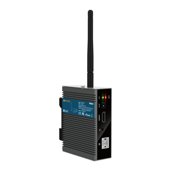
Page 21: Antenna (Optional)
The number of antenna interface is related to the purchasing product model. Here, we take two antenna interfaces as an example. 1.6.11 Motherboard Introducing the interfaces reserved in the ED-IPC2200 series device, which can be obtained only after the device case is opened and can be expanded according to actual needs. ED-IPC2200 Series User Manual... - Page 22 Interface 1.6.11.1 12V 1A Output The motherboard of ED-IPC2200 series device includes 3 expanded 12V 1A power output ports with 2-Pin 2.0mm white WTB connector, which is reserved for the extended LCD screen to supply power. The pins are defined as follows:...
- Page 23 EXIO_P17 1.6.11.3 5V 1A Output The motherboard of ED-IPC2200 series device includes an extended 5V 1A power output port with 3-Pin 2.0mm spacing white WTB connector, which is reserved for the extended LCD screen to supply power. The pins are defined as follows:...
- Page 24 1.6.11.5 FPC DSI (optional) The motherboard of ED-IPC2200 series device includes one extended DSI port, with 30-pin 0.5mm FPC connector and 4-Lane DSI signal. It supports the output of MIPI display signal to LCD screen, reserving to connect the extended LCD screen. It supports USB/I2C touch screen and backlight...
- Page 25 DSI1_D3_P 1.6.11.6 FPC HDMI (optional) The motherboard of ED-IPC2200 series device includes one extended HDMI interface with 40-pin 0.5mm spacing FPC connector. It supports video signal output to LCD screen, reserving to connect the extended LCD screen. It supports USB/I2C touch screen and backlight adjustment The pins are...
- Page 26 USB_DP_LCD USB_DM_LCD 1.6.11.7 USB 2.0 The motherboard of ED-IPC2200 series device includes an extended USB 2.0 Pin Header with 5-Pin 1.5mm spacing WTB connector. It is used to expand a USB 2.0 interface, the pins are defined as follows: ED-IPC2200 Series User Manual...
- Page 27 Pin Name 1.6.11.9 CSI (optional) The motherboard of ED-IPC2200 series device includes one extended CSI interface, with 2x15-Pin 0.4mm spacing connector and 2-Lane CSI signal. It is used to expand to connect 8-megapixels CSI camera, the pins are defined as follows: Note: Only ED-IPC2220 include this interface.
- Page 28 1.6.11.10 RTC Battery Base The motherboard of ED-IPC2200 series device is integrated with RTC. In China, we will install CR1220 battery (RTC backup power supply) by default. RTC can ensure that the system has an uninterrupted and reliable clock, which is not affected by factors such as the device is power off.
- Page 29 1 Product Description 1.6.11.11 mSATA The motherboard of ED-IPC2200 series device includes a mSATA port with mini PCIe connector. It is used to connect a mSATA SSD. ED-IPC2200 Series User Manual 1-20...
-
Page 30: Installing Components (Optional)
2 Installing Components (optional) 2 Installing Components (optional) This chapter describes how to install optional components. Installing Internal Components Installing/Removing External Components ED-IPC2200 Series User Manual... -
Page 31: Installing Internal Components
Pull out the default configuration of phoenix connector (male for wiring). Use a screwdriver to loosen two M3 screws on two sides counterclockwise. Remove the front cover to the right. Use a screwdriver to loosen four M2.5 screws and one grounding screw on two sides counterclockwise. ED-IPC2200 Series User Manual... - Page 32 Remove the upper cover upward and turn it to the antenna port side. Use a screwdriver to loosen the 8 screws fixing the PCBA counterclockwise, remove the upper cover and flip it to the back of the PCBA. ED-IPC2200 Series User Manual...
-
Page 33: Install Rtc Battery
CR1220 batteries. Therefore, before using RTC, please prepare a CR1220 battery and install it on the motherboard. Preparation: The device case has been opened. The CR1220 battery has been prepared. ED-IPC2200 Series User Manual... - Page 34 Locate the RTC battery base where the battery is to be installed, as shown in the red box below. Put the positive pole of the battery upwards and press it into the RTC base. The installation effect is as shown below. ED-IPC2200 Series User Manual...
-
Page 35: Close Device Case
Turn the upper cover downwards, align the ports on PCBA with the ports on each side panel and close the upper cover. Align the screw holes on the upper and side panels and use a screwdriver to tighten four M2.5 screws and one grounding screw on two sides clockwise. ED-IPC2200 Series User Manual... - Page 36 Align the ports on PCBA with the ports on the front panel, insert the front cover. Insert 2 M3 screws and then use a screwdriver to fasten two M3 screws clockwise. Plug in the default phoenix connector. ED-IPC2200 Series User Manual...
-
Page 37: Installing/Removing External Components
2.2 Installing/Removing External Components Introducing the detailed operations of installing/removing some optional accessories. 2.2.1 Install Antenna If the purchasing ED-IPC2200 series device includes 4G and Wi-Fi functions, the antenna need to be installed before using the device. Preparation: The corresponding antennas have been obtained from the packaging box. If there are multiple antennas, they can be distinguished by the labels on the antennas. -
Page 38: Pull Out Sd Card
Please turn off the power before inserting or removing the SD card. Preparation: The device has been disconnected from power. Steps: Find the location of SD card, as shown in the red mark of figure below. ED-IPC2200 Series User Manual... -
Page 39: Install Nano Sim Card
Press the SD card into the card slot with your hand to pop it out, and then pull out the SD card. 2.2.4 Install Nano SIM Card If the purchasing ED-IPC2200 series device includes 4G function, the SIM card need to be installed before using 4G. Preparation: The 4G Nano SIM card is ready. - Page 40 2 Installing Components (optional) Insert the Nano SIM card into the corresponding card slot with the chip side up, and hear a sound to indicate that the installation is completed. Install the DIN-Rail bracket onto the device case. ED-IPC2200 Series User Manual 2-11...
-
Page 41: Installing Device
3 Installing Device 3 Installing Device This chapter introduces how to install the device. DIN-Rail Installation ED-IPC2200 Series User Manual... -
Page 42: Din-Rail Installation
3 Installing Device 3.1 DIN-Rail Installation When the ED-IPC2200 series device leaves the factory, the DIN-rail bracket is installed as standard by default. Steps: Face the side of the DIN-rail bracket to the rail, and sleeve the upper side of the bracket on the upper side of the rail. -
Page 43: Booting The Device
4 Booting The Device 4 Booting The Device This chapter introduces how to connect cables and boot the device. Connecting Cables Booting The System For The First Time ED-IPC2200 Series User Manual... -
Page 44: Connecting Cables
Get the HDMI cable and network cable that can be used normally. Schematic diagram of connecting cables: Please refer to 1.6 Interfaces for the pin definition of each interface and the specific method of wiring. ED-IPC2200 Series User Manual... -
Page 45: Booting The System For The First Time
4 Booting The Device 4.2 Booting The System For The First Time ED-IPC2200 series device does not have a power switch. After the power supply is connected, the system will start. The red PWR indicator is on, indicating that the device has been powered normally. - Page 46 4 Booting The Device ED-IPC2200 Series User Manual...
-
Page 47: Configuring System
Remote Login Configuring Storage Devices Configuring Wi-Fi (Optional) Configuring Ethernet IP Configuring Bluetooth (Optional) Configuring 4G (Optional) Configuring Buzzer Configuring RTC Configuring Audio (Optional) Configuring USER Indicator ED-IPC2200 Series User Manual... -
Page 48: Finding Device Ip
ED-IPC2200 has been connected to the network through the router. Steps: Hover over the network icon in the system tray, and a tooltip will appear. This tooltip displays the name of the network you’re currently connected to and your IP address. ED-IPC2200 Series User Manual... -
Page 49: Hostname Command To Query
Run the following command in the command pane to view the detailed information of each port of the device, where the inet value in the eth1 interface is the device IP, as shown in the following figure. ifconfig ED-IPC2200 Series User Manual... -
Page 50: Query Ip By Using Network Manager Cli
Manager CLI (nmcli) to view details about your network. Preparation: ED-IPC2200 has been connected to the network through the router. Steps: Run the following command in the command pane to view the detailed network information. nmcli device show ED-IPC2200 Series User Manual... -
Page 51: Login Router To Query Ip
192.168.X.X/24, where 24 is the subnet mask. Steps: For example, using nmap to scan the network segments from 192.168.3.0 to 255, you can use the following steps: Open the nmap tool and scan the hosts in the 192.168.X.X/24 network segment. ED-IPC2200 Series User Manual... - Page 52 5 Configuring System NOTE: The nmap tool operates differently in different operating systems, so please follow the actual interface or command prompts. According to the scanned results, get the device IP of ED-IPC2200. ED-IPC2200 Series User Manual...
-
Page 53: Remote Login
IP address of ED-IPC2200 has been get. Steps: Open MobaXterm, click , and open the window for creating connection, as shown in the figure below. Click in the upper left corner to open the SSH connection interface. ED-IPC2200 Series User Manual... - Page 54 Click "Accept" in the pop-up prompt box to enter the system login interface. Enter the username and password according to the prompt, and enter the system after logging in. TIP: Default username is pi, Default password is raspberry. ED-IPC2200 Series User Manual...
-
Page 55: Connect To The Device Desktop Through Vnc
The VNC function in the ED-IPC2200 system has been turned on, as shown in the following figure. Steps: Open RealVNC Viewer and select "New connection…" in the File in the menu bar to open the window for creating a connection, as shown in the following figure. ED-IPC2200 Series User Manual... - Page 56 5 Configuring System After entering the IP address of ED-IPC2200, click "OK". Enter the username and password in the Authentication prompt box that pops up. ED-IPC2200 Series User Manual 5-10...
- Page 57 5 Configuring System TIP: Default username is pi, Default password is raspberry. Select "OK" to log in and connect to the remote desktop. ED-IPC2200 Series User Manual 5-11...
-
Page 58: Configuring Storage Devices
2. Run the following command to view all disk partitions on the ED-IPC2200. sudo lsblk -o UUID,NAME,FSTYPE,SIZE,MOUNTPOINT,LABEL,MODEL After running the command, the information displayed is as follows: UUID、 NAME、 FSTYPE、 SIZE、 MOUNTPOINT、 LABEL and MODEL are disk parameters ED-IPC2200 Series User Manual 5-12... - Page 59 "/mnt", the command to be executed is as follows: sudo mkdir /mnt/mydisk 5. Mount the storage device at the created mount point, and execute the following command: sudo mount /dev/sda1 /mnt/mydisk ED-IPC2200 Series User Manual 5-13...
-
Page 60: Unmount The Storage Device
After executing the command, if an error message is displayed, it means that the unmounting is failed. 5.3.3 Set The Storage Device To Mount Automatically If you are using the Lite version of operating system, you can automatically mount it by modifying the fstab settings. Preparation: ED-IPC2200 Series User Manual 5-14... - Page 61 "read/write" access to each file on the storage device. NOTE: More information about the fstab command can be viewed by executing the man fstab command. 5. Use Ctrl+X to save the file and exit edit mode. ED-IPC2200 Series User Manual 5-15...
-
Page 62: Configuring Wi-Fi (Optional)
In the Lite version of the operating system, Wi-Fi can be enabled through the command line. Setps: Open the command terminal pane and execute the following command to open the Raspberry Pi Software Configuration Tool (raspi-config) interface. ED-IPC2200 Series User Manual 5-16... - Page 63 Choose "5 Localisation Options" and press Enter. Select "L4 WLAN Country" and press Enter. Select a country code according to the actual region and press Enter. Press Enter in "Wireless LAN country set to CN" interface. ED-IPC2200 Series User Manual 5-17...
-
Page 64: Use The Networkmanager Tool To Configure Wi-Fi Connections
In the Desktop version of the operating system, you can connect to Wi-Fi through the desktop icon. Preparation: Wi-Fi function is enabled. Steps: Left-click the icon in the upper right corner of the desktop, select the Wi-Fi to be connected in the pop-up Wi-Fi list and click. ED-IPC2200 Series User Manual 5-18... - Page 65 The Wi-Fi name and password that can be connected are prepared, for example, the Wi-Fi name is SSID and the password is password. Steps: Open the terminal and execute the following command to scan the list of connectable Wi-Fi name. ED-IPC2200 Series User Manual 5-19...
-
Page 66: Configure Wi-Fi Connection By Using Dhcpcd Tool
The Wi-Fi name and password that can be connected are prepared, for example, the Wi-Fi name is EDATEC-WH and the password is password. Steps: Open the terminal and execute the following command to open the Raspberry Pi Software Configuration Tool (raspi-config) interface. sudo raspi-config ED-IPC2200 Series User Manual 5-20... - Page 67 Select "1 System Options" and press Enter, and then select "S1 Wireless LAN" in the interface. Press Enter, then enter the Wi-Fi name in the "Please enter SSID" interface. Press Enter, then enter the Wi-Fi password in the "Please enter passphrase. Leave it empty if none" interface. ED-IPC2200 Series User Manual 5-21...
- Page 68 5 Configuring System Press Enter to connect Wi-Fi. When the Wi-Fi is connected successfully, select "Finish" and press Enter to complete the setting and return to the command line window. ED-IPC2200 Series User Manual 5-22...
-
Page 69: Configuring Ethernet Ip
Preparation: Wi-Fi is enabled. Steps: Left-click the icon and select "Edit Connections…" from the menu. In the pop-up "Network Connections" pane, select the connection name to be modified, and then click the Settings button below. ED-IPC2200 Series User Manual 5-23... - Page 70 If you want to set the IP as a static IP, set the "Method" as "Manual", add an entry in Addresses and enter the corresponding IP address information. If you want to set the IP to automatic mode, you only need to set the "Method" as "Automatic(DHCP) ". ED-IPC2200 Series User Manual 5-24...
- Page 71 192.168.1.101/24 and the gateway IP is 192.168.1.1. Obtain the connection name to be modified, for example e167c45f-efed-3f8d-89a5- f2430f92fae8. In the command pane, run the following command to query the connection name. nmcli c ED-IPC2200 Series User Manual 5-25...
-
Page 72: Configure Ip By Using The Dhcpcd Tool
NetworkManager service and enable the dhcpcd service before configuration. Steps: Execute the following command to stop the NetworkManager service. sudo systemctl stop NetworkManager ED-IPC2200 Series User Manual 5-26... - Page 73 192.168.0.1 indicates the gateway IP to be configured; 8.8.8.8 represents the DNS server address, which should be configured according to the actual needs. fd51:42f8:caae:d92e::1 indicates the IPV6 address, which should be configured according to the actual needs. ED-IPC2200 Series User Manual 5-27...
- Page 74 5 Configuring System Use Ctrl+S to save the file, then enter Ctrl+X to exit edit mode. Execute the following command to reboot the device. sudo reboot ED-IPC2200 Series User Manual 5-28...
-
Page 75: Configuring Bluetooth (Optional)
In the pop-up "Add New Device" pane, view the scanned Bluetooth devices. Then you can select a Bluetooth device, and click “Pair” to start pairing. Select “OK” in the pop-up prompt box to confirm the pairing request. ED-IPC2200 Series User Manual 5-29... -
Page 76: Raspberry Pi Os(Lite)
Disconnect device 5.6.2.2 Configuration Example This chapter introduces how to configure Bluetooth through a configuration example. Preparation: The Bluetooth to be paired has been enabled and its name has been determined. Steps: Enter the Bluetooth view. ED-IPC2200 Series User Manual 5-30... - Page 77 The Bluetooth device to be connected also needs to confirm the pairing request, otherwise the pairing will fail. Add as trusted device. trust 34:12:F9:91:FF:68 34:12:F9:91:FF:68 is target device’s device_MAC Returned display information: [CHG] Device 34:12:F9:91:FF:68 Trusted: yes Changing 34:12:F9:91:FF:68 trust succeeded ED-IPC2200 Series User Manual 5-31...
-
Page 78: Configuring 4G (Optional)
Customize a gsm network name (for example, 4G2) and get the name of APN (for example, apn1). Execute the following command to create a gsm network named 4G2. sudo nmcli connection add type gsm con-name 4G2 ifname cdc-wdm0 gsm.apn apn1 ED-IPC2200 Series User Manual 5-32... -
Page 79: Configure The Network By Using The Dhcpcd Tool
Execute the following command to enable the "lte-reconnect.service" service. sudo systemctl enable lte-reconnect.service Execute the following command to start the "lte-reconnect.service" service and make automatic dialing. sudo systemctl start lte-reconnect.service Execute the following command to check the status of the wwan interface. ED-IPC2200 Series User Manual 5-33... -
Page 80: Configure 4G Module Reset
Execute the following command to restart the "lte-reconnect.service" service. sudo systemctl restart lte-reconnect.service 5.7.3 Configure 4G Module Reset When the device fails to recognize the SIM card, you can reset the 4G module through the command line. ED-IPC2200 Series User Manual 5-34... - Page 81 Execute the following commands to detect and install gpiod tools. sudo apt update sudo apt install gpiod Execute the following command to reset the 4G module. gpiofind 4G_RST | awk '{print substr($0,9)}' | xargs -i bash -c "gpioset {}=0" ED-IPC2200 Series User Manual 5-35...
-
Page 82: Configuring Buzzer
BUZZER_EN | awk '{print substr($0,9)}' | xargs -i bash -c "gpioset {}=1" 1 indicates the high level. Turn off the buzzer: gpiofind BUZZER_EN | awk '{print substr($0,9)}' | xargs -i bash -c "gpioset {}=0" 0 indicates the low level. ED-IPC2200 Series User Manual 5-36... -
Page 83: Configuring Rtc
RTC. Execute the following command to read the RTC time manually. sudo hwclock -r Execute the following command to write the system time into RTC. sudo hwclock -w ED-IPC2200 Series User Manual 5-37... -
Page 84: Configuring Audio (Optional)
Both Desktop and Lite versions of the operation system support opening the volume adjustment interface through the command line to adjust the volume. Steps: 1. Execute the following command to open the volume adjustment interface. alsamixer ED-IPC2200 Series User Manual 5-38... - Page 85 4. Press Enter to open the volume interface of MIC and Speaker, and you can adjust the volume of MIC and Speaker respectively through the key and key on the keyboard, and press M to mute and unmute MIC/Speaker. Keyboard Key Function Volume+ Volume- Mute or Unmute ED-IPC2200 Series User Manual 5-39...
-
Page 86: Configure Record
3. Press Esc to exit to the command pane, execute the following command to start recording audio named audio1, as shown in the figure below. arecord -fcd -Dhw:1 -c 1 --vumeter=mono audio1 | aplay -fcd -Dhw:1 ED-IPC2200 Series User Manual 5-40... - Page 87 Indicates the recorded file name, which can be customized by the user. 4. Use Ctrl+C to close recording. 5. Execute the following command to obtain the storage path of the recording file. ED-IPC2200 Series User Manual 5-41...
-
Page 88: Configuring User Indicator
USER_LED | awk '{print substr($0,9)}' | xargs -i bash -c "gpioset {}=0" 0 indicates the high level. Turn off the USER indicator: gpiofind USER_LED | awk '{print substr($0,9)}' | xargs -i bash -c "gpioset {}=1" 1 indicates the low level. ED-IPC2200 Series User Manual 5-42...
Need help?
Do you have a question about the ED-IPC2200 Series and is the answer not in the manual?
Questions and answers