Table of Contents
Advertisement
Quick Links
Advertisement
Table of Contents

Related Manuals for EDA ED-CM4IND


Summary of Contents for EDA ED-CM4IND
- Page 1 ED-CM4IND User Manual by EDA Technology Co., Ltd built: 2025-02-14...
-
Page 2: Product Overview
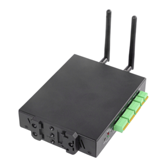
ED-CM4IND 1 Product Overview The ED-CM4IND is an industrial embedded computer based on the Raspberry Pi CM4. Depending on the application scenarios and user requirements, it offers a variety of configurations for RAM, eMMC, or SD card storage. • The available RAM options include 1GB, 2GB, 4GB and 8GB. -
Page 3: Specifications
ED-CM4IND 1.2 Specifications Function Parameters Broadcom BCM2711 quad-core Cortex-A72 (ARM v8) 64-bit SoC @ 1.5GHz 1GB/2GB/4GB/8GB optional eMMC 0GB/8GB/16GB/32GB optional Micro SD card Supports 32GB SD card if CM4 without eMMC is selected Extended storage 1 x 4MB Serial Flash... -
Page 4: System Diagram
ED-CM4IND Function Parameters V1.4: 9V ~ 36V DC Input Power V1.1~V1.3: 9V ~ 18V DC Dimensions 170mm (L) x 120mm (W) x 30mm (H) Enclosure Full metal enclosure, supports DIN rail mounting Antenna Accessories Supports optional WiFi/BT antenna and 4G antenna Operating -25°C to 50°C... -
Page 5: Functional Layout
ED-CM4IND 1.4 Functional Layout Function Function 3 × ADC Debug serial port 1 × RS232 Custom GPIO Pin Header 2 × RS485 DC Power Socket 2 × DI 1000M Ethernet Port 2 × Relay 100M Ethernet Port Reset Button 2 × USB 2.0... -
Page 6: Packing List
Function Mini PCIe interface CM4 Socket Standard SIM Card Slot 1.5 Packing List • 1 x ED-CM4IND Unit • [WiFi/BT Version - optional] 1 x 2.4GHz/5GHz WiFi/BT Antenna • [4G Version - optional] 1 x 4G/LTE Antenna 1.6 Ordering Code Email: sales@edatec.cn / support@edatec.cn... -
Page 7: Quick Start
1 x 12V 2A power adapter • 1 x CR1220 button battery (RTC power supply) 2.2 Hardware Connection As an example, the ED-CM4IND that includes eMMC, WiFi/BT and 4G functions is used to introduce the specific operation of the connection. Tools and wires preparation: •... - Page 8 ED-CM4IND If you use the standard Raspberry Pi OS, and the OS is not configured before flasing to eMMC, the Welcome to Raspberry Pi application will pop up and guide you to complete the initialization setting when you start it for the first time.
- Page 9 ED-CM4IND Input a new password for the default account , and click Next and default password is raspberry Select the wireless network you need to connect to, enter the password, and then click Next If the device does not support WiFi function, there will be no this step. Before upgrading the system, you need to wait for the wifi connection to work (wifi icon appears in the top right corner).
- Page 10 ED-CM4IND Click Restart to complete the system update. 2.3.2 Raspberry Pi OS(Lite) If you are using the default OS, the system boots up and automatically logs you in using the username pi, with a default password of raspberry. Email: sales@edatec.cn / support@edatec.cn Phone: +86-15921483028(China) | +86-18217351262(Overseas) Web: www.edatec.cn...
- Page 11 ED-CM4IND If you use the standard Raspberry Pi OS (lite), and the OS is not configured before flasing to eMMC, the configuration window will appear when you start it for the first time. You need to configure the keyboard layout, set the user name and the corresponding password.
-
Page 12: Enable Ssh
ED-CM4IND Then set the password corresponding to the user according to the prompt, and enter the password again for confirmation. At this point, you can log in with the user name and password you just set. 2.3.3 Enable SSH If you use the standard Raspberry Pi OS, you need to enable the SSH function. -
Page 13: Wiring Guide
Taking ADC1 as an example, the wiring diagram of analog signal input is as follows: 3.1.2 DI The ED-CM4IND contains 2 isolated DI interfaces. There are two wiring methods for the digital input signals, dry contact (passive) wiring and wet contact (active) wiring. - Page 14 The connection diagram of PNP type sensor is as follows. If you do not use an external power supply to power the sensor, you can use the Vout provided by ED-CM4IND for power supply. The connection diagram for PNP type sensors using Vout power supply is as follows: Vout can only provide 12V power output.
- Page 15 If you do not use an external power supply to power the sensor, you can use the Vout provided by ED-CM4IND for power supply. The connection diagram for NPN type sensors using Vout power supply is as follows: Vout can only provide 12V power output.
- Page 16 ED-CM4IND 3.1.3 Realy The relay output interfaces NC, COM, NO, correspond to the normally closed, common, and normally open of the relays respectively, and the relays of ED-CM4IND are double-knife, double- throw relays. • When the control relay is closed, NO1 and NO2 are closed with respect to COM1 and COM2.
-
Page 17: Microsd Card Slot
Taking RS485-1 interface as an example, the wiring diagram is as follows: 3.1.6 Micro SD Card slot There is a Micro SD card slot on ED-CM4IND. Please insert the Micro SD card face up into the Micro SD card slot. - Page 18 ED-CM4IND 3.2.2 CSI It is recommended that a 15-pin 1mm pitch single-sided FPC connector cable be used to connect to the CSI interface, with the metal contact side facing up and inserted in a direction perpendicular to the FPC connector, as shown in the figure below.
- Page 19 ED-CM4IND 4 Software Operation Guide 4.1 Finding Device IP Finding Device IP 4.2 Remote Login Remote Login 4.3 Configuring Storage Devices Configuring Storage Devices 4.4 Configuring Ethernet IP Configuring Ethernet IP 4.5 Configuring Wi-Fi (Optional) Configuring Wi-Fi 4.6 Configuring Bluetooth (Optional) Configuring Bluetooth 4.7 Configuring 4G (Optional)
- Page 20 ED-CM4IND sudo nmcli connection type gsm con-name mobilegsm • APN needs to be configured. sudo nmcli connection type gsm con-name <connection_name> ifname cdc-wdm0 gsm.apn "cmnet" • configure username and password sudo nmcli connection type gsm con-name <connection_name> ifname cdc-wdm0 gsm.number "#777"...
- Page 21 4.8 RTC ED-CM4IND is integrated with RTC. For the version sold in China, we will install CR1220 button cell (RTC backup power supply) by default when shipping. In this way, the system can be guaranteed to have an uninterrupted and reliable clock, which is not affected by factors such as equipment power down.
-
Page 22: User Button
GPIO 6: level=0 fsel=0 func=INPUT pull=UP A level of 0 indicates that the GPIO6 pin is low. 4.10 Buzzer The buzzer control pin of ED-CM4IND is GPIO25. Open buzzer: Email: sales@edatec.cn / support@edatec.cn Phone: +86-15921483028(China) | +86-18217351262(Overseas) Web: www.edatec.cn... -
Page 23: Spi Flash
6 op 4.11 SPI Flash The ED-CM4IND is extended with a SPI Flash via SPI with a memory capacity of 4MB for user data storage. On Linux, Serial Flash is recognized as an MTD (Memory Technology Device) /dev/mtd0 device, and the device file of Flash on ED-CM4IND is MTD devices are different from our common Block devices such as hard disk, SD card, U- disk and EMMC. -
Page 24: Serial Communication
Input Ctrl+a first, then Ctrl+q to exit picocom. 4.12.2 Configure RS232 ED-CM4IND includes 1 RS232 port, and the corresponding COM ports and device files are as follows: Email: sales@edatec.cn / support@edatec.cn Phone: +86-15921483028(China) | +86-18217351262(Overseas) Web: www.edatec.cn... - Page 25 115200. picocom 115200 /dev/ttyAMA3 Input commands as needed to control external device. 4.12.3 Configure RS485 ED-CM4IND includes 2 RS485 port, and the corresponding COM ports and device files are as follows: RS485 Port Corresponding Device File RS485-1 /dev/ttyAMA2 RS485-2...
- Page 26 /boot/cmdline.txt 4.13 ADC There are 3 ADC channels on ED-CM4IND. Take AIN1 as an example to demonstrate how to read them: /sys/bus/iio/devices iio\:device0 in_voltage1_raw 4.14 DI The ED-CM4IND contains 2 channels of DI, which are connected to GPIO11 and GPIO26 of the CM4.
- Page 27 GPIO 26: level=0 fsel=0 func=INPUT pull=DOWN 4.15 Relay The ED-CM4IND features an onboard double-pole double-throw (DPDT) relay, controlled by the GPIO22 pin's high or low level. By default, the relay is in the normally closed (NC) state, where COM1 is connected to NC1 and COM2 is connected to NC2. When GPIO22 is set to a high level, the relay switches to the open state, connecting COM1 to NO1 and COM2 to NO2.
- Page 28 ED-CM4IND 5 Installing OS (optional) The device is shipped with an operating system by default. If the OS is corrupted during use or the user needs to replace the OS, it is necessary to re-download the appropriate system image and install it.
- Page 29 The OS file has been obtained. Steps: The steps are described using Windows system as an example. Open the top cover of the ED-CM4IND device, determine the location of the Micro USB port, and then connect USB flashing cable and power cables. •...
- Page 30 ED-CM4IND According to the prompt, select the OS file under the user-defined path and return to the main page. Click "CHOOSE STORAGE", select the default device in the "Storage" interface, and return to the main page. Click “NEXT”, select "NO " in the pop-up “Use OS customization?” pane.
- Page 31 ED-CM4IND After the OS writing is completed, the file will be verified. After the verification is completed, click “CONTINUE” in the pop-up “Write Successful” box. Close Raspberry Pi Imager, remove USB cable and power on the device again. 5.3 Installing Firmware Package After you have finished flashing to eMMC on ED-IPC2000 Series, you need to configure the system by adding edatec apt source and installing firmware package to make the system work.
- Page 32 ED-CM4IND After the installation is complete, the system automatically reboots. Execute the following command to check whether the firmware package is installed successfully. dpkg grep The result in the picture below indicates that the firmware package has been installed successfully.
Need help?
Do you have a question about the ED-CM4IND and is the answer not in the manual?
Questions and answers