Table of Contents
Advertisement
Quick Links
Advertisement
Table of Contents

Related Manuals for EDA EDATEC ED-HMI2630-101C


Summary of Contents for EDA EDATEC ED-HMI2630-101C
- Page 1 ED-HMI2630-101C User Manual by EDA Technology Co., Ltd built: 2024-10-29...
-
Page 2: Packing List
ED-HMI2630-101C 1 Hardware Manual This chapter introduces the product overview, packing list, appearance, button, indicator and interface. 1.1 Overview ED-HMI2630-101C is an industrial HMI based on Raspberry Pi CM4. According to different application scenarios and user needs, different specifications of RAM and eMMC computer systems can be selected. -
Page 3: Front Panel
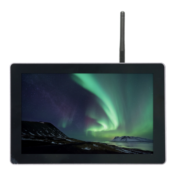
ED-HMI2630-101C 1.3 Appearance Introducing the functions and definitions of interfaces on each panel. 1.3.1 Front Panel This section introduces functions and definitions of front panel. Function Definition Function Definition 1 x LCD display, 10.1-inch LCD touch screen, which supports up to 1280x800 and multi-point capacitive touchscreen. -
Page 4: Side Panel
ED-HMI2630-101C Function Definition 5 x installation holes of buckle, which are used to fix the buckles to the device for installation. You only need to use 4 installation holes during installation, and reserve one as a spare. 1.3.3 Side Panel This section introduces interfaces and definitions of side panel. - Page 5 ED-HMI2630-101C Function Definition 8 x green DO indicators, which is used to check the communication status of DO signal. 2 x green CAN indicators, which is used to check the communication status of CAN signal. 8 x green DI indicators, which is used to check the communication status of DI signal. 1 x 10/100M adaptive Ethernet port, RJ45 connector, with led indicator.
- Page 6 ED-HMI2630-101C Indicator Status Description The device has been powered on. Power supply of the device is abnormal, please stop the power Blink supply immediately. The device is not powered on. Blink The system started successfully and is reading and writing data. The device is not powered on or does not read and write data.
- Page 7 ED-HMI2630-101C 1.6.1 Card Slot ED-HMI2630-101C includes an SD card slot and a Nano SIM card slot. 1.6.1.1 SD Card Slot The silkscreen on the case of Micro SD card slot is " ", which is used to install SD card for storing user data.
- Page 8 ED-HMI2630-101C • ED-HMI2634-101C:4 x RS485(without RS232) The silkscreen of RS485 single port is ‘IGND/A/B’, the silkscreen of RS232 single port is ‘IGND/ TX/RX’, and 3.5mm pitch phoenix terminals . Pin Definition Terminal pins are defined as follows: Pin ID Pin Name RS485-2_B RS485-4_B RS485-2_A...
- Page 9 ED-HMI2630-101C The RS485 wiring schematic is as follows: The RS232 wiring schematic is as follows: RS485 terminal resistance configuration ED-HMI2630-101C includes 2~4 RS485 ports, 120R jumper resistor is reserved between A and B of each RS485 line, plug in the jumper cap to enable the jumper resistor. The 120R termination resistor function is disabled when the jumper cap is not connected in the default state.
- Page 10 ED-HMI2630-101C COMX0 COMX1 Connecting Cables The wiring schematic for the single DI port is shown as follows: Parameters Instructions Input Type NPN and PNP Isolation Protection 5 kV Every 4 DI ports share one common pin (called COM): X0, X2, X4 and X6 share COMX0 X1, X3, X5 and X7 share COMX1 ON state: 5~30 VDC DI to COM...
-
Page 11: Can Interface
ED-HMI2630-101C COMY0 COMY1 Connecting Cables The wiring schematic for the single DO port is shown as follows: Parameters Instructions Output Type Transistor Isolation Protection 5 kV Every 4 DI ports share one common terminal (called COM): Y0, Y2, Y4 and Y6 share COMY0 Y1, Y3, Y5 and Y7 share COMY1 Output 5~30 VDC (24 VDC is recommended), maximum current is 1.5A (per channel) - Page 12 ED-HMI2630-101C CAN1H CAN0L CAN1L Connecting Cables The wiring schematic for the CAN ports is shown as follows: 1.6.9 1000M Ethernet Interface ED-HMI2630-101C includes an adaptive 10/100/1000M Ethernet port, and the silkscreen is " ". When accessing to network, it is recommended to use the network cable of Cat6 and above.
- Page 13 ED-HMI2630-101C 1.6.14 Antenna Interface (Optional) ED-HMI2630-101C includes 2 SMA antenna connectors, the silkscreens are "4G" and "Wi-Fi/BT" and they can be connected to the 4G antenna and Wi-Fi/BT antenna. The number of antenna port is related to the actual model selected by the user, and only 2 antenna ports are included here as an example.
-
Page 14: Installing Components
ED-HMI2630-101C 2 Installing Components This chapter describes how to install optional components. 2.1 Install Antenna If the selected ED-HMI2630-101C includes 4G and Wi-Fi functions, you will need to install the antenna before using the device. Preparation: The corresponding antennas have been obtained from the packaging box. If there are multiple antennas, they can be distinguished by the labels on the antennas. - Page 15 ED-HMI2630-101C 2.3 Install Nano SIM Card (optional) If the selected ED-HMI2630-101C includes 4G function, you will need to install a SIM card before using the device. Preparation: The 4G Nano SIM card to be used has been obtained. Steps: Find the location of the Nano SIM card slot on the device, as shown in the red box on the figure below.
-
Page 16: Installing Device
ED-HMI2630-101C 3 Installing Device This chapter introduces how to install the device. 3.1 Embedded Installation ED-HMI2630-101C device supports embedded front installation and the optional ED-ACCHMI- Front accessory kit (includes 4xbuckles, 4xM4*10 screws and 4xM4*16 screws). Preparation: • ED-ACCHMI-Front accessory kit has been obtained (contains 4xbuckles, 4xM4*10 screws and 4xM4*16 screws). - Page 17 ED-HMI2630-101C Align the screw hole (unthreaded hole) of the buckle with the buckle installation hole on the device. Use 4xM4*10 screws to pass through the buckle and tighten it clockwise to fix the buckle to the device; then use 4xM4*16 screws to pass through the screw hole (threaded hole) of the buckle and tighten clockwise to the end through the buckles.
-
Page 18: Booting The Device
ED-HMI2630-101C 4 Booting the Device This chapter introduces how to connect cables and boot the device. 4.1 Connecting Cables This section describes how to connect cables. Preparation: • Accessories such as display, mouse, keyboard and power adapter that can be used normally have been ready. - Page 19 ED-HMI2630-101C 4.2 Booting The System For The First Time ED-HMI2630-101C device has no switching power supply. After the power supply is connected, the system will start. • The red PWR indicator is on, indicating that the device has been powered normally. •...
- Page 20 ED-HMI2630-101C 4.2.1 Raspberry Pi OS(Desktop) If the Desktop version of the system is installed when the product leaves the factory, after the device is started, it will directly enter the desktop, as shown in the following figure. 4.2.2 Raspberry Pi OS (Lite) If the Lite version of the system is installed at the factory, the default username pi will be used to automatically log in after the device is started, and the default password is raspberry.
-
Page 21: Configuring System
ED-HMI2630-101C 5 Configuring System This chapter introduces how to configure system. 5.1 Finding Device IP Finding Device IP 5.2 Remote Login Remote Login 5.3 Configuring Storage Devices Configuring Storage Devices 5.4 Configuring Ethernet IP Configuring Ethernet IP 5.5 Configuring Wi-Fi (Optional) Configuring Wi-Fi 5.6 Configuring Bluetooth (Optional) Configuring Bluetooth... -
Page 22: Configuring Serial Port
ED-HMI2630-101C 5.10 Configuring Serial Port This chapter introduces the configuration method of RS232 and RS485. 5.10.1 Installing picocom tool In the Linux environment, you can use the picocom tool to debug the serial ports RS232 and RS485. Execute the following command to install the picocom tool. sudo apt-get install picocom 5.10.2 Configuring RS232... - Page 23 ED-HMI2630-101C 5.10.3 Configuring RS485 ED-HMI2630-101C includes 2~4 RS485 ports with their corresponding COM ports and device files, as shown in the table below: ED-HMI2632-101C Number of RS485 Ports Corresponding COM Port Corresponding Device File COM2, COM4 /dev/com2, /dev/com4 ED-HMI2633-101C Number of RS485 Ports Corresponding COM Port Corresponding Device File COM2, COM3, COM4...
- Page 24 ED-HMI2630-101C sudo apt update sudo apt install gpiod Execute the following command to read the data from the corresponding DI port. gpiofind DI0 '{print substr($0,9)}' xargs bash "gpioget • DI0 indicates the corresponding port number. 5.12 Configuring DO The ED-HMI2630-101C includes 8 DO ports, which can be configured according to the actual requirement.
- Page 25 ED-HMI2630-101C 5.13 Configuring CAN 5.13.1 Installing can-utils tool Execute the following commands in sequence to detect and install the can-utils tool. sudo apt update sudo apt install can-utils 5.13.2 Setting CAN state Preparation: The connection of the CAN port of the ED-HMI2630-101C to external devices has been completed.
-
Page 26: Configuring Audio
ED-HMI2630-101C 123#1122334455667788 is the message to be sent, which can be customised by the user according to the format. 5.14 Configuring Audio Configuring Audio 5.15 Configuring USER Indicator Configuring USER Indicator Email: sales@edatec.cn / support@edatec.cn Phone: +86-15921483028(China) | +86-18217351262(Overseas) Web: www.edatec.cn...
Need help?
Do you have a question about the EDATEC ED-HMI2630-101C and is the answer not in the manual?
Questions and answers