Table of Contents
Advertisement
Quick Links
Advertisement
Table of Contents

Related Manuals for EDA ED-HMI3120-101C


Summary of Contents for EDA ED-HMI3120-101C
- Page 1 ED-HMI3120-101C User Manual by EDA Technology Co., Ltd built: 2025-01-09...
-
Page 2: Packing List
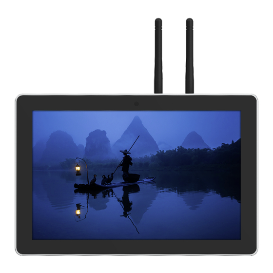
This chapter introduces the product overview, packing list, appearance, button, indicator and interface. 1.1 Overview ED-HMI3120-101C is a 10.1-inch industrial HMI based on Raspberry Pi CM5. According to different application scenarios and user needs, different specifications of RAM and eMMC computer systems can be selected. -
Page 3: Front Panel
ED-HMI3120-101C 1.3.1 Front Panel Introducing the front panel interface types and definitions. Function Definition 1 x LCD display, 10.1-inch LCD touch screen, which supports up to 1280x800 resolution and multi-point capacitive touchscreen. 1 x camera (optional), 8-megapixel front camera. 1.3.2 Rear Panel Introducing the types and definitions of the rear panel interface. -
Page 4: Side Panel
ED-HMI3120-101C Function Definition 5 x installation holes of buckle, which are used to fix the buckles to the device for installation. You only need to use 4 installation holes during installation, and reserve one as a spare. 1.3.3 Side Panel Introducing the types and definitions of side panel interfaces. - Page 5 1 x Micro-SD card slot, which is used to install SD card for storing user data. 1.4 Button ED-HMI3120-101C includes a RESET button, which is a hidden button, and the silkscreen on the case is "RESET". Pressing the RESET button will reset the device.
-
Page 6: Power Supply Interface
Introducing the definition and function of each interface in the product. 1.6.1 Card Slot ED-HMI3120-101C includes a Micro SD card slot and a Nano SIM card slot. 1.6.1.1 Micro SD Card Slot The silkscreen on the case of Micro SD card slot is "... -
Page 7: Audio Interface
ED-HMI3120-101C Pin ID Pin Name 9V~36V 1.6.3 Audio Interface ED-HMI3120-101C includes one audio input, the connector is a 3.5mm 4-pole headphone jack. The silkscreen of port is " ", which supports OMTP stereo headphone output and mono microphone recording. •... - Page 8 UART2_RXD Connecting Cables Schematic diagram of RS232 wires is as follows: 1.6.6 RS485 ED-HMI3120-101C include 2 RS485 ports, 6-Pin 3.5mm pitch phoenix terminals. The silkscreen of single RS485 is “IGND/A/B”. Pin Definition Terminal pins are defined as follows: Pin ID...
-
Page 9: 1000M Ethernet Interface
ED-HMI3120-101C RS485 terminal resistance configuration ED-HMI3120-101C contain 2 RS485 ports. A 120R jumper resistor is reserved between A and B of RS485 line. The jumper cap can be inserted to enable the jumper resistor. By default, the jumper cap is not connected, and the 120R jumper resistor function is disabled. The position of jumper resistor in the PCBA are J24 and J22 in the figure below (red box position). -
Page 10: Hdmi Interface
Pin ID Pin Name 1.6.9 HDMI Interface ED-HMI3120-101C includes one HDMI port, the silkscreen is "HDMI". The connector is type A HDMI, which can connect to an HDMI display and supports up to 4Kp60. 1.6.10 USB 2.0 Interface ED-HMI3120-101C includes 2 USB2.0 ports, the silkscreen is "... - Page 11 The number of antenna interface is related to the purchasing product model. Here, we take two antenna interfaces as an example. 1.6.13 Motherboard Interface Introducing the interfaces reserved in the ED-HMI3120-101C, which can be obtained only after the device case is opened and can be expanded according to actual needs. Function...
- Page 12 ED-HMI3120-101C 1.6.13.2 10-Pin GPIO The motherboard of ED-HMI3120-101C includes a 10-Pin GPIO Pin Header with 2x5-Pin 2.54mm pitch, which is used to lead out the extended GPIO port. The user can customize the extension, and the pins definition are as follows:...
- Page 13 SSD. It is compatible with M.2 B 2230 and M.2 B 2242 SSD. 1.6.13.5 RTC Battery Base The motherboard of ED-HMI3120-101C is integrated with RTC. For the version sold in China, we will install CR1220 battery (RTC backup power supply) by default.
- Page 14 CR1220 battery and install it on the motherboard. 1.6.13.6 USB 2.0 Interface The motherboard of ED-HMI3120-101C includes an extended USB 2.0 Pin Header with 5-Pin 1.5mm pitch WTB connector. It is used to expand a USB 2.0 interface, the pins are defined as...
- Page 15 SDA_1V8 1.6.13.8 FPC HDMI Interface The motherboard of ED-HMI3120-101C includes one extended HDMI interface with 40-Pin 0.5mm pitch FPC connector. It supports video signal output to LCD screen, reserves to connect the extended LCD screen. It supports USB/I2C touch screen and backlight adjustment. The pins are...
- Page 16 ED-HMI3120-101C Email: sales@edatec.cn / support@edatec.cn Phone: +86-15921483028(China) | +86-18217351262(Overseas) Web: www.edatec.cn...
- Page 17 ED-HMI3120-101C 2 Installing Components (optional) his chapter describes how to install optional components. 2.1 Installing Internal Components (optional) Introducing the detailed operations of opening/closing the device case and installing the RTC battery. Before installing the internal components, it is necessary to open the device case.
- Page 18 ED-HMI3120-101C Use a screwdriver to loosen the 8 screws fixing the PCBA counterclockwise, and flip it to the back of the PCBA. 2.1.2 Install RTC battery Some international logistics do not support the transportation of batteries, and some ex- factory devices are not equipped with CR1220 batteries. Therefore, before using RTC, please prepare a CR1220 battery and install it on the motherboard.
- Page 19 ED-HMI3120-101C Steps: Locate the RTC battery base where the battery is to be installed, as shown in the red box below. Put the positive pole of the battery upwards and press it into the RTC base. The installation effect is as shown below.
- Page 20 ED-HMI3120-101C Flip the metal case upward, align the screw mounting holes on the metal case with the screw mounting holes on the back of the LCD screen, and cover it downward on the back of the LCD screen. Align the screw holes on side panels of metal case, insert 4 M3 screws and one grounding screw, then tighten clockwise with a screwdriver.
-
Page 21: Install Antenna
2.2 Installing/Removing External Components Introducing the detailed operations of installing/removing some optional accessories. 2.2.1 Install Antenna If the purchasing ED-HMI3120-101C includes 4G and Wi-Fi functions, the antenna need to be installed before using the device. Preparation: The corresponding antennas have been obtained from the packaging box. If there are multiple antennas, they can be distinguished by the labels on the antennas. - Page 22 Press the Micro SD card into the card slot with your hand to pop it out, and then pull out the Micro SD card. 2.2.4 Install Nano SIM Card If the purchasing ED-HMI3120-101C device includes 4G function, the Nano SIM card need to be installed before using 4G. Preparation: The 4G Nano SIM card is ready.
- Page 23 ED-HMI3120-101C Email: sales@edatec.cn / support@edatec.cn Phone: +86-15921483028(China) | +86-18217351262(Overseas) Web: www.edatec.cn...
-
Page 24: Installing Device
• A cross screwdriver has been prepared. Steps: You need ensure the opening size of the cabinet according to the size of ED-HMI3120-101C, as shown in the figure below. Unit: mm Drill a hole on the cabinet according to the hole size of step1. - Page 25 ED-HMI3120-101C Align the screw hole (unthreaded hole) of the buckle with the buckle mounting hole on the side of the device. Use 4 M4*10 screws to pass through the buckle and tighten it clockwise to fix the buckle to the device;...
- Page 26 ED-HMI3120-101C Email: sales@edatec.cn / support@edatec.cn Phone: +86-15921483028(China) | +86-18217351262(Overseas) Web: www.edatec.cn...
-
Page 27: Booting The Device
4.2 Booting The System For The First Time ED-HMI3120-101C has no switching power supply. After the power supply is connected, the system will start. • The red PWR indicator is on, indicating that the device has been powered normally. - Page 28 ED-HMI3120-101C Default username is , Default password is raspberry 4.2.1 Raspberry Pi OS (Desktop) If the Desktop version of the system is installed when the product leaves the factory, after the device is started, it will directly enter the desktop, as shown in the following figure.
-
Page 29: Configuring System
ED-HMI3120-101C 5 Configuring System This chapter introduces how to configure system. 5.1 Finding Device IP Finding Device IP 5.2 Remote Login Remote Login 5.3 Configuring Storage Devices Configuring Storage Devices 5.4 Configuring Ethernet IP Configuring Ethernet IP 5.5 Configuring Wi-Fi (Optional) Configuring Wi-Fi 5.6 Configuring Bluetooth (Optional) -
Page 30: Configuring Serial Port
Execute the following command to install the picocom tool. sudo apt-get install picocom 5.10.2 Configuring RS232 ED-HMI3120-101C includes 2 RS232 ports, and the corresponding COM ports and device files are as follows: Number of RS232 Ports Corresponding COM Port Corresponding Device File... -
Page 31: Configuring Audio (Optional)
ED-HMI3120-101C The RS485 port of ED-HMI3120-101C has been connected with external devices. Steps: Execute the following command to open the serial port com4, and configure the serial port baud rate to 115200. picocom 115200 /dev/com4 Input commands as needed to control external devices. - Page 32 ED-HMI3120-101C 6 Installing OS (optional) The device is shipped with an operating system by default. If the OS is corrupted during use or the user needs to replace the OS, it is necessary to re-download the appropriate system image and install it.
- Page 33 Connecting to power cord: One end is connected to the DC 2-Pin Phoenix terminal on the device side, and the other end is connected to the external power supply. Disconnect the power supply of ED-HMI3120-101C and then power it on again. Disking through a Linux PC is performed as follows.
- Page 34 ED-HMI3120-101C usbboot/ make d. Execute the following command to the mass-storage-gadget64 directory. mass-storage-gadget64 e. Disconnect the ED-HMI3120-101C power supply and power it up again. f. Execute the following commands in the mass-storage-gadget64 directory to start disk symbolization. sudo ../rpiboot The device does not need to be powered off after the Linux PC is successfully disked, unplug the end of the USB flashing cable connected to the Linux PC, and then plug it into the USB port of the windows PC, and the disk will pop up in the lower right corner of the Windows PC.
- Page 35 ED-HMI3120-101C In the pop-up prompt box, select "Yes". When the formatting is completed, click "OK" in the prompt box. Close SD Card Formatter. Open Raspberry Pi Imager, select "CHOOSE OS" and select "Use Custom " in the pop-up pane. According to the prompt, select the OS file under the user-defined path and return to the main page.
- Page 36 Close Raspberry Pi Imager, remove USB cable and power on the device again. 6.3 Installing Firmware Package After you have finished flashing to eMMC on ED-HMI3120-101C, you need to configure the system by adding edatec apt source and installing firmware package to make the system work.
- Page 37 ED-HMI3120-101C Preparation: • The flashing to eMMC of the Raspberry Pi standard OS (bookworm) has been completed. • The device has booted normally and the relevant boot configuration has been completed. Steps:: After the device starts normally, execute the following commands in the command pane to add the edatec apt source and installing firmware package.
Need help?
Do you have a question about the ED-HMI3120-101C and is the answer not in the manual?
Questions and answers