
Related Manuals for Generac Power Systems MIH1.2


Summary of Contents for Generac Power Systems MIH1.2
- Page 1 MIH1.2 Indirect Fired Heater Owner’s Manual For technical assistance contact: www.generacmobileproducts.com Technical Support 1-800-926-9768 SAVE THIS MANUAL FOR FUTURE REFERENCE...
- Page 2 Use this page to record important information about your mobile heater Record the information found on your unit data label on Unit Model No. this page. See Unit Serial Number Locations. Engine and generator serial numbers are located on data Unit Serial No.
-
Page 3: Table Of Contents
General Troubleshooting Guide ...... 25 Unit Serial Number Locations ......8 Component Locations .........9 Section 6: Wiring Diagrams Interior ...............10 MIH1.2 Cabin (1 of 4) ........31 Heater ................11 MIH1.2 Cabin (2 of 4) ........32 Control Panel .............12 Emissions ............12 MIH1.2 Cabin (3 of 4) ........ - Page 4 Tire Safety ..............40 Basic Tire Maintenance ..........40 Finding Your Vehicle’s Recommended Tire Pressure And Load Limits ..............40 Understanding Tire Pressure And Load Limits ....40 Checking Tire Pressure ..........41 Steps For Maintaining Proper Tire Pressure ....41 Tire Size .................
-
Page 5: Section 1: Introduction And Safety
Offshore drilling rigs maintained properly. • Painting and coating locations The MIH1.2 indirect fired heater is designed and built for • Airline hanger heat sustained, reliable heat production in industrial operating •... -
Page 6: How To Obtain Service
Introduction and Safety CAUTION WARNING Hot Surfaces. When operating machine, do not Indicates a hazardous situation which, if not avoided, touch hot surfaces. Keep machine away from could result in minor or moderate injury. combustibles during use. Hot surfaces could result in severe burns or fire. -
Page 7: Trailer Hazards
Introduction and Safety WARNING WARNING Risk of Fire. Unit must be positioned in a Property or equipment damage. Do not alter the manner that prevents combustible material trailer. Alterations can damage essential safety items. accumulation underneath. Failure to do so Doing so could result in death, serious injury, or could result in death or serious injury. -
Page 8: Towing Safety
Introduction and Safety • Safe Towing Techniques Replace all missing and hard to read decals. Decals provide important operating instructions • Practice turning, stopping, and backing up in an and warn of dangers and hazards. area away from heavy traffic prior to transporting the unit. -
Page 9: Safety And Operating Decals
Introduction and Safety Safety and Operating Decals Figure 1-1. This unit features numerous safety and use care when washing and cleaning the unit. Decal part operating decals. These decals provide important operat- numbers can be found in the unit parts manual at ing instructions and warn of dangers and hazards. - Page 10 Introduction and Safety This page intentionally left blank. Owner’s Manual for Indirect Fired Heater...
-
Page 11: Section 2: General Information
Section 2: General Information Specifications Description Unit of Measure MIH1.2 Engine ® Make (Model) — Isuzu (3CE1) EPA Certification tier 4 Final Type — Naturally aspirated Horsepower At Operating Speed hp (kW) 21.1 (15.7) Operating Speed 1,800 Displacement 97.6 (1.6) -
Page 12: Unit Dimensions
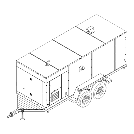
General Information Unit Dimensions 010063 Figure 2-1. MIH1.2 254 in (4.72 m) 96 in (2.44 m) 101 in (2.57 m) Unit Serial Number Locations Figure 2-2 for unit ID tag and Vehicle Identification information from these tags so it is available if the tags Number (VIN) tag. -
Page 13: Component Locations
General Information Component Locations 014978 Figure 2-3. Exterior Components Engine exhaust Engine access door Burner exhaust Tie-down point (4 locations) Rear support jack (if equipped) Control panel access door Fork lift pocket (4 locations) Trailer jack Fuel Fill Air inlet guard Reflector (multiple locations) Hot air discharge duct Power receptacle (120 V, 20 A, GFCI) -
Page 14: Interior
General Information Interior 014960 Figure 2-4. Interior Components Engine starter (hidden by engine) Engine oil level gauge (dipstick) Engine alternator (hidden by engine) Water separator assembly (not shown) Fuel Inlet Engine fuel pump (not shown) Fuel Return Engine fuel filter Battery Generator Engine radiator... -
Page 15: Heater
General Information Heater 014961 Figure 2-5. Heater Components Thermostat Diesel-fired burner Electrical junction box Burner reset button Fan limit controller Burner fuel filter Owner’s Manual for Indirect Fired Heater... -
Page 16: Control Panel
General Information Control Panel 008962 Figure 2-6. Control Panel Engine control box and ignition Blower STOP button Fuel gauge Blower ON indicator lamp Burner ON-OFF switch Blower OFF indicator lamp Blower START button Control panel main disconnect switch Emissions CAUTION The United States Environmental Protection Agency (US EPA) (and California Air Resources Board (CARB), for Engine damage. -
Page 17: Wheel Chock Guidelines
General Information DANGER Explosion and Fire. Do not overfill fuel tank. Overfilling may cause fuel to leak and ignite or explode, resulting in death or serious injury. (000204) The heater is designed to operate with diesel fuel. IMPORTANT NOTE: Comply with all laws regulating the storage, handling, and transporting of fuels. - Page 18 General Information This page intentionally left blank. Owner’s Manual for Indirect Fired Heater...
-
Page 19: Section 3: Operation
Section 3: Operation • Before Starting Engine The unit must be located at least 16 feet (5 m) away from where the ground is subject to large, rapids amount of erosion. Pre-start Checklist • Inspect the generator. See the generator manual. •... -
Page 20: Ducting Guidelines
Operation ant according to Table 4-1, or if it is contaminated or dirty. See Adding Coolant. WARNING Ducting Guidelines Equipment damage. Do not attempt to start or operate a unit in need of repair or scheduled maintenance. Doing so could result in serious injury, death, or DANGER equipment failure or damage. -
Page 21: Adjusting Heater Output
Operation Engine and Heater Shutdown NOTE: Do not use starting aids, such as gasoline. Doing so will damage the engine. CAUTION Adjusting Heater Output Equipment damage. Shut down the heater before If OFF is set to 180 °F (82 °C) and ON is set to 170 °F turning off the generator. -
Page 22: Thermostat Control
Operation Thermostat Control 1. On the Main Screen, press Menu. The LCD dis- plays OFF, which is the first parameter code screen. 2. Press Menu to set desired temperature. 3. Press Menu to save value. 4. Press Up or Down to reach ON setting. 5. -
Page 23: Section 4: Maintenance
Section 4: Maintenance Maintenance Draining and Refilling the Oil Regular maintenance will improve performance and WARNING extend engine/equipment life. Generac Mobile recom- mends that all maintenance work be performed by a Risk of burns. Allow engine to cool before GMASD. Regular maintenance, replacement, or repair of draining oil or coolant. -
Page 24: Maintenance Schedule
Maintenance 3. See Figure 4-2. Remove radiator cap (A). WARNING Risk of burns. Contents under pressure. Do not remove the radiator pressure cap while engine is hot. Doing so could result in death or serious injury. (000322a) WARNING Risk of burns. Do not open coolant system until engine has completely cooled. - Page 25 Maintenance Table 4-1. Maintenance Schedule • Check engine oil level. • Check fuel level. • Check engine coolant level. Daily • Drain water from fuel filters. • Inspect air cleaner, dust unloader valve, and indicator. • Perform visual walk around inspection. •...
-
Page 26: Battery Inspection
Maintenance Battery Inspection A GMASD should inspect the battery system once every six months. At this time, the battery condition and state of charge should be checked using a load test battery. DANGER Recharge or replace the battery as required. Battery service is to be performed or supervised by per- Electrocution. -
Page 27: Other Maintenance Checks
Maintenance • Other Maintenance Checks After starting the engine, let it warm up for more than 10 minutes at idle. The following inspections should be performed by an authorized service technician, or a properly trained auth- orized operator. These maintenance items require a high level of experience and skill to evaluate and correct. - Page 28 Maintenance This page intentionally left blank. Owner’s Manual for Indirect Fired Heater...
-
Page 29: Section 5: Troubleshooting
Section 5: Troubleshooting General Troubleshooting Guide Problem Cause Solution Low battery output voltage or discharged Charge or replace batteries. See Bat- battery. tery Inspection. Loose or corroded connections. Clean and tighten connections. Faulty start circuit relay. Contact a GMASD. Engine does not crank Blown fuse. - Page 30 Troubleshooting Problem Cause Solution Poor fuel quality; incorrect fuel/dirty fuel. Test fuel, drain water from fuel bowl. Restricted fuel filter. Replace fuel filter element. Water, dirt, or air in fuel system. Drain, flush, fill, and purge fuel system. Engine misfiring or runs Low coolant temperature.
- Page 31 Troubleshooting Problem Cause Solution Restricted fuel return line. Check and fix fuel return lines. Fuel in oil Engine load too light. Increase engine load. Leaking fuel injectors. Contact a GMASD. Restricted fuel filter. Replace fuel filter. Restricted fuel line. Locate restriction, repair as required. Low-pressure fuel system Faulty transfer pump.
- Page 32 Troubleshooting Problem Cause Solution Replace air cleaner element as Restricted or dirty air cleaner. required. Drain fuel and replace with proper Incorrect type of fuel. grade, type, and quality of fuel for oper- ating condition. Engine emits black, gray, or Engine burning oil.
- Page 33 Troubleshooting Problem Cause Solution Drain crankcase and refill with correct Insufficient crankcase oil viscosity. viscosity oil. See Draining and Refill- ing the Oil. Drain oil until oil level is correct. See Excessive crankcase oil. Draining and Refilling the Oil. Determine source of oil leak(s) and External oil leak(s).
- Page 34 Troubleshooting This page intentionally left blank. Owner’s Manual for Indirect Fired Heater...
-
Page 35: Section 6: Wiring Diagrams
Section 6: Wiring Diagrams MIH1.2 Cabin (1 of 4) GROUP G WIRE COLOR TSHL WIRNG - DIAGRAM REVISION: CN-0065231-C MIH1.2 CABIN PAGE 1 OF 4 DRAWING #: A0000261123 DATE: 12/27/22 Owner’s Manual for Indirect Fired Heater... -
Page 36: Mih1.2 Cabin (2 Of 4)
Wiring Diagrams MIH1.2 Cabin (2 of 4) GROUP G COMPONENTS LOCATED IN CONTROL BOX MLCB CB1 CB2 GNDL GNDB WIRING - DIAGRAM REVISION: CN-0065231-C MIH1.2 CABIN PAGE 2 OF 4 DRAWING #: A0000261123 DATE: 12/27/22 Owner’s Manual for Indirect Fired Heater... -
Page 37: Mih1.2 Cabin (3 Of 4)
Wiring Diagrams MIH1.2 Cabin (3 of 4) GROUP G MLCB GNDB GNDL SCHEMATIC - DIAGRAM REVISION: CN-0065231-C MIH1.2 CABIN PAGE 3 OF 4 DRAWING #: A0000261123 DATE: 12/27/22 Owner’s Manual for Indirect Fired Heater... -
Page 38: Mih1.2 Cabin (4 Of 4)
Wiring Diagrams MIH1.2 Cabin (4 of 4) GROUP G COMPONENTS LOCATED IN ENGINE BAY 12VDC FUEL FILTER HEATERS FFHR FFH1 50W 12VDC FFH2 50W 12VDC EGND COMPONENTS LOCATED ON FUEL TANK SCHEMATIC - DIAGRAM REVISION: CN-0065231-C MIH1.2 CABIN PAGE 4 OF 4... -
Page 39: Trailer Wiring Harness
Wiring Diagrams Trailer Wiring Harness Owner’s Manual for Indirect Fired Heater... - Page 40 Wiring Diagrams This page intentionally left blank. Owner’s Manual for Indirect Fired Heater...
-
Page 41: Section 7: Nhtsa Trailer Equipment Requirements
Section 7: NHTSA Trailer Equipment Requirements Reporting Safety Defects to the – Calculating total and cargo load capacities with United States Government varying seating configurations including quantitative examples showing/illustrating how If you believe your trailer has a defect which could cause the vehicle’s cargo and luggage capacity a crash or could cause injury or death, you should decreases as the combined number and size of... -
Page 42: Trailers 10,000 Lbs (4,536 Kg) Gvwr Or Less
NHTSA Trailer Equipment Requirements 5. Determine the combined weight of luggage and to your dealer to discuss the weighing methods needed to capture the various weights related to the trailer. This cargo being loaded on the vehicle. That weight would include the weight empty or unloaded, weights per may not safely exceed the available cargo and lug- axle, wheel, hitch or king-pin, and total weight. - Page 43 NHTSA Trailer Equipment Requirements Hitch weight means the downward force exerted on the Overall width means the linear distance between the hitch ball by the trailer coupler. exteriors of the sidewalls of an inflated tire, including elevations due to labeling, decorations, or protective Innerliner means the layer(s) forming the inside surface bands or ribs.
-
Page 44: Tire Safety
NHTSA Trailer Equipment Requirements • Tread means that portion of a tire that comes into contact Improve fuel economy with the road. • Increase the life of your tires Tread rib means a tread section running circumferentially This booklet presents a comprehensive overview of tire around a tire. -
Page 45: Checking Tire Pressure
NHTSA Trailer Equipment Requirements tire pressure for your vehicle is referred to as the placard or certification label. While your tire may still be “recommended cold inflation pressure.” (As you will read slightly underinflated due to the extra pounds of pressure below, it is difficult to obtain the recommended tire in the warm tire, it is after to drive with air pressure that is pressure if your tires are not cold.) -
Page 46: Information On Passenger Vehicle Tires
NHTSA Trailer Equipment Requirements characteristics of the tire and also provides a tire G U.S. DOT Tire Identification Number. This begins identification number for safety standard certification and with the letters “DOT” and indicates that the tire in case of a recall. meets all federal standards. -
Page 47: Temperature A
NHTSA Trailer Equipment Requirements Temperature A Additional Information on Light Truck Tires All passenger car tires must conform to federal safety requirements in addition to these grades. Treadwear The treadwear grade is a comparative rating based on the war rate of the tire when tested under controlled conditions on a specified government test course. -
Page 48: Preventing Tire Damage
NHTSA Trailer Equipment Requirements • Preventing Tire Damage Inspect tires for cracks, foreign objects, uneven • wear patterns on the tread, or other signs of wear Slow down if you have to go over a pothole or other or trauma. object in the road. - Page 49 NHTSA Trailer Equipment Requirements This page intentionally left blank. Owner’s Manual for Mobile Generator Sets...
- Page 50 NHTSA Trailer Equipment Requirements This page intentionally left blank. Owner’s Manual for Mobile Generator Sets...
- Page 52 Part No. A0000244062 Rev. B 08/17/2023 ©2023 Generac Power Systems, Inc. All rights reserved. Generac Power Systems, Inc. Specifications are subject to change without notice. S45 W29290 Hwy. 59, Waukesha WI 53189 No reproduction allowed in any form without prior written consent GeneracMobileProducts.com...
Need help?
Do you have a question about the MIH1.2 and is the answer not in the manual?
Questions and answers