Hexagon veripos LD8 Operation Manual
Hide thumbs
Also See for veripos LD8:
- Operation manual (41 pages) ,
- Installation manual (33 pages) ,
- Quick start manual (2 pages)
Advertisement
Quick Links
Advertisement

Related Manuals for Hexagon veripos LD8


Summary of Contents for Hexagon veripos LD8
- Page 1 Operations Manual AB-V-MA-00635_RevA11 06 February 2024...
- Page 2 Contents 1 Introduction 1.1 General information 1.2 LD8 receiver 1.3 System requirements 1.4 Veripos Support 1.5 Activating Veripos correction services 1.6 Terms and abbreviations 1.7 Document conventions 1.8 LD8 Notices 1.9 Disclaimer 2 Hardware overview 2.1 Overview and description 2.2 LEDs 2.3 Interface panel connections 3 Ethernet and WebUI connection 3.1 Ethernet...
- Page 3 7 Appendix 7.1 L-band coverage map LD8 Operations Manual...
- Page 4 1.1 General information 1 Introduction 1.1 General information To assist with LD8 operation, it will help to have the following items available when consulting this document: LD8 and associated equipment shipped to the site. A PC or Laptop meeting the system requirements specified below The Delivery note provided within the shipment from Veripos.
- Page 5 It is available 24 hours a day, 365 days per year. Full contact details are available in the Contact information section. For support cases, contact support.veripos@hexagon.com or raise a ticket at https://help.veripos.com. Either method will immediately notify Veripos Support, who will then assist.
- Page 6 1.6 Terms and abbreviations 1.6 Terms and abbreviations Alternating Current APEX Veripos high accuracy positioning solution BEIDOU Chinese commissioned GNSS Decibel DHCP Dynamic Host Configuration Protocol Dilution of Precision Dynamic Positioning Differential Quality Indicator European Union GALILEO European commissioned GNSS GLONASS GLObal NAvigation Satellite System - Russian commissioned GNSS GNSS Global Navigation Satellite System...
- Page 7 1.6 Terms and abbreviations User Accuracy Level User Interface Ultra Veripos high accuracy position solution Universal Serial Bus Coordinated Universal Time Volts Direct Current VDOP Vertical Dilution of Precision VOSS Veripos Online Support System WAAS Wide Area Augmentation System WebUI Web User Interface WEEE Waste Electrical and Electronic Equipment...
- Page 8 1.7 Document conventions 1.7 Document conventions 1.7.1 Typographical conventions Italic or bold text is used to emphasize certain information. Italic is also used in cross-references to other parts of the document and to other documents. Bold text is also used for indicators and touch screen “push-buttons” commands. Blue text is used for hyperlinking to other sections within this document or to external documents or websites.
- Page 9 1.8 LD8 Notices 1.8 LD8 Notices The following notices apply to the LD8: 1.8.1 Waste electrical and electronic equipment The Waste Electrical and Electronic Equipment Directive (hereinafter referred to as the “WEEE directive”) places an obligation on EU-based manufacturers, distributors, retailers and importers to take- back electronics products at the end of their useful life.
- Page 10 1.8 LD8 Notices 1.8.2 FCC This device complies with part 15 of the FCC Rules. Operation is subject to the following two conditions: (1) this device may not cause harmful interference, and (2) this device must accept any interference received, including interference that may cause undesired operation. LD8 has been tested and found to comply with the radiated and conducted emission limits for a Class B digital device.
- Page 11 1.8 LD8 Notices 1.8.3 European Union / United Kingdom (UK) 1.8.3.1 Radio Equipment Directive Veripos declares that the LD8 including its Wi-Fi transceiver is in compliance with: 1. EU Directive 2014/53/EU 2. UK Regulations S.1. 2017/1206 The full text of either the UK or EU Declaration of Conformity may be obtained from Veripos upon request.
- Page 12 Nothing herein constitutes a binding obligation on Hexagon. The information contained herein is subject to change without notice. © Copyright 2024 Hexagon AB and/or its subsidiaries and affiliates. All rights reserved. A list of entities within the Hexagon Autonomy & Positioning division is available at https://hexagon.com/company/divisions/autonomy-and-positioning.
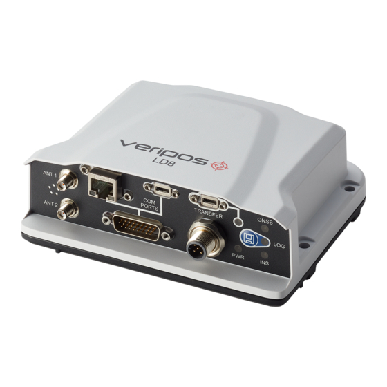
- Page 13 2.1 Overview and description 2 Hardware overview This section describes the physical characteristics of the LD8, provides information on the different possible LED statuses and details the interface panel inputs. 2.1 Overview and description The LD8 is a small, lightweight and low power system. Veripos provide a +9 to +36 VDC power supply with the LD8.
- Page 14 2.2 LEDs 2.2.3 LOG LED State Description LD8 is connected to a computer as a mounted device Green blink Logging to internal memory Green solid Internal logging stopped Green/yellow alternating blink Logging to internal memory with low memory available Yellow solid Internal logging stopped with low memory available Yellow fast blink Memory is busy...
- Page 15 2.3 Interface panel connections 2.3 Interface panel connections This section details the antenna and data connectivity available from the LD8 interface panel. 2.3.1 Coaxial The LD8 interface panel is fitted with two SMA antenna connectors labelled ANT 1 and ANT 2: Interface panel of LD8 with two GNSS antenna connectors The L-band and GNSS position antenna should be connected to the ANT 1 connector.
- Page 16 3.1 Ethernet 3 Ethernet and WebUI connection The LD8 supports Ethernet (10Base-T/100Base-TX) for configuration and interfacing to other vessel systems. The Ethernet port supports IPv4 Internet layer and TCP/IP transport. 3.1 Ethernet A PC or laptop with an Ethernet port and an up-to-date version of Microsoft Edge, Mozilla Firefox or Google Chrome is required to configure the LD8 for operation.
- Page 17 4.1 WebUI status 4 Configuration and operation The two ways in which the LD8 can be configured are by using Veripos Quantum software, or by using the LD8 WebUI. Quantum must be used if being used for system monitoring. If Quantum is not available, system configuration must be performed through the WebUI, which features a terminal application that can be used for sending commands.
- Page 18 4.1 WebUI status 4.1.1 WebUI Status page items At the top of the page is a summary bar containing key system information. Below this, the main body of the LD8 WebUI Home > Status page is split into several boxes, with each box containing useful system information: Item Description...
- Page 19 4.2 LD8 password Sending commands will trigger one of three different responses from the LD8: Status response When requesting system status information, such as querying which L-band beam/s are presently being tracked, the LD8 should respond with an ‘<OK’ echo, followed by the requested information. Acknowledgement response When successfully making a configuration change a single or multiple line response containing ‘<OK>’...
- Page 20 4.3 LD8 firmware 4.3 LD8 firmware To verify the present firmware on the LD8, send the below command: LOG VERSION The following information will appear in the terminal program. The firmware version has been highlighted: GPSCARD "FDDRYNTVEA" "DMMU205000412" "OEM7720-1.01" "OM7CR0814RN0000 OEM7FPGA """OMV070001RN0000" "" DEFAULT_CONFIG "" """""EP7CD0814RN0001"...
- Page 21 4.4 L-band configuration 4.4 L-band configuration Tracking of an L-band beam is required to receive Veripos service correction and activation data. This section will detail how to establish and confirm successful L-band tracking to make use of Veripos services. Auto Beam is the recommended way to manage L-band beam choices. When in this mode, the LD8 will track up to three beams simultaneously with tracking determined based on available L-band satellites and elevation and data received from each L-band satellite used within the calculation.
- Page 22 4.4 L-band configuration 4.4.2 Selecting Auto beam via terminal To enable the use of Auto beam enter the following: ASSIGNLBANDBEAM AUTO 4.4.3 Selecting a single beam via terminal The format for assigning a specific L-band beam (98W, AORW, 25E, IOR, 143.5) is as follows: ASSIGNLBANDBEAM BEAMNAME 4.4.4 Entering a custom beam frequency via terminal A custom L-band beam name and frequency (in Hz) can be manually entered, however this should be...
- Page 23 4.4 L-band configuration 4.4.6 HDR mode configuration via terminal Enabling HDR mode can assist with L-band tracking when potential interference sources are present. HDR Mode uses signal processing to dampen potential sources of RF distortion, at the cost of increased CPU usage.
- Page 24 (>36.5 dB). Tracking of a L-band beam is required as activation and deactivation updates are sent via the beam. Email Veripos Support (support.veripos@hexagon.com) with the Unit ID, Vessel Name, SAL number and services required. NOTE Veripos Support cannot enable services unless an active SAL exists.
- Page 25 4.5 Activation and deactivation of Veripos services In the below terminal output, the unit has been successfully activated and the unit ID has been highlighted, followed by the service activation code: VERIPOSINFO WCOM1 0 66.0 FINESTEERING 2039 314993.573 02008020 2bd7 14970 <123456 NCC_CONTROLLED 80000111 "2"...
- Page 26 4.6 Calculation configuration 4.6 Calculation configuration There are several calculation configuration options which can be changed by the use of commands. These configuration options can update the way in which Veripos service types are utilised. 4.6.1 PPP mode selection via terminal The two PPP solutions that Veripos offer, Ultra and APEX, allow for decimetre accuracy positioning.
- Page 27 4.6 Calculation configuration 4.6.3 SBAS configuration via terminal The LD8 SBAS mode can be enabled or disabled via the terminal. The SBAS positioning mode can be enabled by entering: SBASCONTROL ENABLE AUTO The SBAS positioning mode can be disabled by entering: SBASCONTROL DISABLE 4.6.4 Heading offset and output frequency via WebUI The Heading can be turned on or off from the Heading switch.
- Page 28 4.7 Ethernet configuration 4.7 Ethernet configuration Network connectivity to the LD8 is essential for configuration and implementing changes. The following sub-sections detail how to check and change the present IP address settings. 4.7.1 IP configuration via WebUI IP addresses can be checked and configured by navigating to Settings > Networking. Within the Ethernet Window, the DHCP setting can be toggled to Off or On.
- Page 29 4.7 Ethernet configuration 4.7.3 Setting a static IP via terminal The LD8 is preconfigured with a static IP of 192.168.2.8, however this IP address can be changed to a different static IP address. The command to change to a static IP follows the structure of: IPCONFIG [interface_name] [address_mode] [IP_address] [netmask] [gateway] An example for this:...
- Page 30 4.8 Output configuration 4.8 Output configuration The LD8 is capable of outputting Veripos RTCM data and a selection of message formats via the following: Serial outputs are available for reference within commands or selected in the WebUI by using ‘COM1’, ‘COM2’ and ‘COM3’. TCP/IP output can be established to one of five ports: 3001, 3002, 3003, 3004 and 3005.
- Page 31 4.8 Output configuration 4.8.1 Configuring message outputs via WebUI Navigate to Configuration > Ports, where configuration of COM 1-3, ICOM 1-5 and USB 1-3 ports is available. Using command variables to specify message type, enter the appropriate command variable next to the required COM, ICOM or USB port in the Messages field. Select the command variable once it appears in the Messages field as shown below and then click Apply to confirm settings.
- Page 32 4.8 Output configuration 4.8.3 Message output rate via WebUI Once a NovAtel command variable has been specified a cog wheel will appear within the right hand corner of the Messages field: Clicking on the settings cog will open a Message Settings window where an output rate can be specified in the Period field.
- Page 33 4.8 Output configuration 4.8.5 Disabling message outputs via terminal To disable a message from being output, the command below should be issued to the unit. This consists of the command required, the port and the message type: UNLOG COM1 GPGGA To stop all output messages on a single port, the command below can be issued stating the port: UNLOGALL COM1 4.8.6 Setting GGA precision selection via terminal...
- Page 34 4.8 Output configuration 4.8.9 Setting PPS via terminal The LD8 allows for the PPS polarity to be configured and set to an increase in pulse from 0v (POSITIVE) or a decrease in pulse to 0v (NEGATIVE). The pulse has a width of 2000 microseconds. An example of the PPSCONTROL command is given below which shows the pulse being set to POSITIVE: PPSCONTROL ENABLE POSITIVE...
- Page 35 4.9 Input configuration 4.9 Input configuration The LD8 is capable of utilising corrections from external sources of Veripos RTCM (RTCM v2, RTCM v3 or CMR) and RTK correction data. For RTK solutions the position will be output in the datum of the correction source.
- Page 36 4.10 Rolling log 4.10 Rolling log 4.10.1 Viewing rolling log via WebUI The LD8 is preconfigured to utilise a rolling data log. This data can be used to conduct various types of analysis or for troubleshooting purposes by Veripos. From this data, RINEX observation logs can be generated, if required.
- Page 37 4.11 Factory reset 4.10.2 Downloading logs Hourly-separated logs can be found within Device > Export. Each log file will be displayed with a date, time stamp and also the file size. As the rolling log builds up there may be multiple pages of stored logs. To download logs, an FTP transfer utility such as FileZilla needs to be used.
- Page 38 5.1 Commands list index 5 Reference information 5.1 Commands list index Commands used within this manual are listed below. Highlighted text should be changed as required. Command Description The format for assigning a ASSIGNLBANDBEAM specific L-band beam Setting for automatically ASSIGNLBANDBEAM AUTO tracking L-band beams PSRDIFF 2 Set PPP DQI to 2 or 5...
- Page 39 5.1 Commands list index Command Description solution Specify a baud rate for a COM1 9600 SERIALCONFIG N 8 1 N OFF specified port SERIALCONFIG COM1 115200 N 8 1 N OFF Input external RTCM INTERFACEMODE COM1 VERIPOS_RTCM NOVATEL ON specifying port and baud rate Disable message output on a UNLOG COM1 GPGGA...
- Page 40 5.2 LD8 output sentences 5.2 LD8 output sentences This section outlines the structure of the following message output types: TRINAV Veripos UKOOA BESTPOS 5.2.1 NMEA talker IDs The NMEA talker identifier serves to define the nature of the data being transmitted. The talker is the first two characters after the $ sign within the NMEA sentence.
- Page 41 5.2 LD8 output sentences 5.2.2 GGA sentence The NMEA GGA sentence contains time and position fix related data for a GPS system. It includes basic quality information, which is limited to ‘Fix Quality’, ‘Number of Satellites in Use’, ‘HDOP’ and ‘Age of Corrections’.
- Page 42 5.2 LD8 output sentences 5.2.3 GST sentence The NMEA GST sentence provides error statistics of the position fix. These statistics follow from the position calculation process. GST sentence structure & example $GNGST, hhmmss.ss, a.aa, b.bb, c.cc, d.dddd, e.ee, f.ff, g.gg *hh $GNGST, 024603.00, 1.47, 0.11, 0.07, 28.3688, 0.10, 0.08, 0.16 *58 GST sentence defined Field...
- Page 43 5.2 LD8 output sentences 5.2.4 ZDA sentence The NMEA ZDA sentence provides time and time zone information. ZDA sentence structure & example $GPZDA, hhmmss.ss, dd, mm, yyyy, null, null *hh $GPZDA, 201530.00, 04, 07, 2019, , ZDA sentence defined Field Content Time and Date data hhmmss.ss UTC time in hours, minutes, seconds of the GPS position...
- Page 44 5.2 LD8 output sentences 5.2.5 GSA sentence The NMEA GSA sentence provides time and time zone information. GSA sentence structure & example $GNGSA, a, 1, cc, cc, cc, cc, cc, cc, cc, cc, cc, cc, cc, cc, d.d, e.e, f.f *hh $GNGSA, a, b, 02, 12, 15, 20, 21, 24, 25, 29, 32, , 1.7, 0.9, 1.5 *58 GSA sentence defined...
- Page 45 5.2 LD8 output sentences 5.2.6 VTG sentence The NMEA VTG sentence provides the actual course and speed relative to the ground. VTG sentence structure & example $GNVTG, ppp.ppp, T, qqq.qgg, M, rr.rrr, N, ss.sss, K, U, *hh $GNVTG, 167.608, T, 167.608, M, 0.006, N, 0.012, K, D, *3D VTG sentence defined Field Content...
- Page 46 5.2 LD8 output sentences 5.2.7 GSV sentence The NMEA GSV sentence provides information relating to the number of satellites (SV) in view, satellite ID numbers, elevation, azimuth, and SNR value in one sentence. GSV sentence structure & example $GPGSV, a, b, cc, dd, ee, fff, gg, dd, ee, fff, gg, dd, ee, fff, gg, dd, ee, fff,...
- Page 47 5.2 LD8 output sentences 5.2.8 GLL sentence The NMEA GGL sentence provides Latitude and Longitude position data for the present position. GLL sentence structure & example $GNGLL, ddmm.mmmmmmm, a, dddmm.mmmmmmm, b, hhmmss.ss, S, I *hh $GNGLL, 5708.7104685, N, 00217.1169613, W, 062859.00, A, D *72 GLL sentence defined Field Content...
-
Page 48: Table Of Contents
5.2 LD8 output sentences 5.2.9 GRS sentence The NMEA GRS sentence provides range residuals for each satellite. GRS sentence structure & example $GNGRS, hhmmss.ss, a, b.b, b.b, b.b, b.b, b.b, b.b, b.b, b.b, b.b, b.b, b.b, b.b, ,cc ,dd *67 $GNGRS, 142406.00, 1, -1.1, -0.1, 1.7, 1.2, -2.0, -1.3, 1.3, -0.4, -1.2, -0.2, , 1, 1, GRS sentence defined... -
Page 49: All Signals L1 C/A
5.2 LD8 output sentences GNSS Constellation: QZSS GNSS System ID: 5 (GQ) Signal Channel: All Signals L1 C/A L1C (D) L1C (P) L2C-M L2C-L Ranging Signal ID: LD8 Operations Manual... - Page 50 5.2 LD8 output sentences 5.2.10 RMC sentence The NMEA RMC sentence provides essential GPS PVT (position, velocity, time) data. RMC sentence structure & example $GNRMC, hhmmss.ss, a, ddmm.mmmmmmm, b, dddmm.mmmmmmm, c, dd.ddd, eee.e, ddmmyy f.f, g, h *hh $GNRMC, 143909, A, 5107.0020216, N, 11402.3294835, W, 0.036,...
- Page 51 5.2 LD8 output sentences 5.2.11 HDT sentences (V3 & V4) The NMEA HDT sentence provides heading information derived from the receiver. HDT sentence structure & example $GNHDT, dd.dddd, T hh $GNHDT, 75.5664, T *36 HDT sentence defined Field Content Heading (true) message dd.dddd Heading in degrees Degrees True Checksum...
- Page 52 5.2 LD8 output sentences 5.2.12 TRINAV sentences (V3 & V4) TRINAV version 3 sentence example [WGPOS,3,1,OEM7VERI,APEX5,OM7MR0702AN0006,1041,392609.00,0.0,57 12.08207N,002 11.53782W,114.421,0.7,1.2,,0.005948,0.000899,0.004640,0.030111,0.14,3,1,3,16,0,1,8,10,11,14,20,2 2,27,28,32,65,66,67,73,81,82,] TRINAV version 3 sentence defined Field Content Unit Notes Start character $WGPOS Format version = 3 for this version Nav. point no. See comment 1 System name/version A Name + version of DGPS system.
- Page 53 5.2 LD8 output sentences TRINAV version 3 definitions commentary 1. The "Nav point no." is a unique integer identifying the position. It should be manually entered into the software according to requests from Positioning Engineers. Alternatively, this should start from 1 and be incremented if several positions are output from the same system. 2.
- Page 54 5.2 LD8 output sentences TRINAV version 4 sentence example [WGPOS,4,1,OEM7VERI,APEX5,OM7MR0702AN0006,1041,396729.00,0.0,57 12.08195N,002 11.53806W,113.340,0.7,0.9,,0.285460,0.009316,0.156003,0.663714,1.33,3,2,G,R,1,0,0,0,1,M3,IOR,2 5E,AORW,18,2,G01,G03,G08,G10,G11,G14,G17,G18,G22,G28,G32,R02,R03,R09,R11,R17,R18,R19 ,777,706,] TRINAV version 4 sentence defined Field Content Unit Notes Start character $WGPOS Format version = 4 for this version Nav. point no. See comment 2 Application name and version, space separated e.g. System Quantum 3.0.0.0 Service level...
- Page 55 5.2 LD8 output sentences Field Content Unit Notes Phases biases used or not to perform ambiguity resolution. PPP-AR Value of 1 indicates a PPP-AR solution, 0 it is not. Use of external atmospheric corrections in computation Atmospheric Value of 1 shows it has atmospheric correction applied, 0 it corrections hasn’t.
- Page 56 5.2 LD8 output sentences 3. Veripos statistics are implemented as per the IMCA/OGP ‘Guidelines for GNSS positioning in the oil & gas industry’ Report No. 373-19 or IMCA S015, June 2011, unless otherwise indicated. 6. TRINAV V4 fix status codes: Status code Meaning No or bad fix Altitude aiding (weighted height used in fix)
- Page 57 5.2 LD8 output sentences 5.2.13 Veripos UKOOA sentence The Veripos UKOOA sentence is compliant with OGP 373-19 and IMCA S015 (July 2011). For further information relating to these standards please visit https://www.iogp.org and https://www.imca-int.com. Veripos UKOOA sentence structure & example [ 240 7300 VERI 1 2067 295238.0 +0.1 +8.0 057 12.08207N 002 11.53776W 63.997 +50.40 1.151 0.564 1.004 7 0.025 0.054 0.14 0.001 0.000 0.000 0.003 0.06 0.05 6.5 P 15{ 20 27 13 30 26 8 21 16 7 10 15 85 77 75 86} 1{ 481}]...
- Page 58 5.2 LD8 output sentences Field Content Notes 109…110 Fix Status Single Frequency 0 = None 4 = None or Bad or Bad 0 = None or Bad Fixes Fixes Fixes Altitude 5 = Altitude Aiding Aiding (weighted 1 = Altitude Aiding (weighted height) (weighted height) height)
- Page 59 5.2 LD8 output sentences Field Content Notes Satellite PRN Numbers of Variable PRN numbers are space separated Satellites used in Number of Reference Variable Stations used for this Fix (00 – 99) Ids of the Reference Variable Station ID numbers are space separated Stations used in the Fix End of Character...
- Page 60 5.2 LD8 output sentences 5.2.14 BESTPOS sentence The BESTPOS sentence contains time and position fix related data for a GPS system. It includes basic quality information, which is limited to ‘Fix Quality’, ‘Number of Satellites in Use’, ‘HDOP’ and ‘Age of Corrections’.
- Page 61 5.2 LD8 output sentences Field Content 23. xxxx 32-bit CRC (ASCII and Binary only) 24. [CR][LF] Sentence terminator (ASCII only) LD8 Operations Manual...
- Page 62 All initial contacts regarding technical or support issues should be initially addressed to Veripos Support. Where appropriate Support will refer issues to the regional operations and engineering teams. 6.1 Veripos Support details Veripos Support website https://veripos.com/support Veripos Support telephone +44 1224 965900 Veripos Support e-mail support.veripos@hexagon.com LD8 Operations Manual...
- Page 63 7.1 L-band coverage map 7 Appendix 7.1 L-band coverage map LD8 Operations Manual...
Need help?
Do you have a question about the veripos LD8 and is the answer not in the manual?
Questions and answers