Hexagon veripos LD8 Operation Manual
Hide thumbs
Also See for veripos LD8:
- Operation manual (63 pages) ,
- Installation manual (33 pages) ,
- Quick start manual (2 pages)
Table of Contents
Advertisement
Quick Links
Advertisement
Table of Contents

Subscribe to Our Youtube Channel
Related Manuals for Hexagon veripos LD8


Summary of Contents for Hexagon veripos LD8
- Page 1 Operations Manual AB-V-MA-00635_RevA6 14 June 2021...
-
Page 2: Table Of Contents
Contents Contents Introduction ..........................3 LD8 Receiver................................3 Scope ................................... 3 System Requirements..............................3 VERIPOS Helpdesk ..............................3 Enabling the LD8 for VERIPOS services ........................ 4 Terms and Abbreviations............................5 Document Conventions.............................. 6 Waste Electrical and Electronic Equipment ......................7 Disclaimer .................................. -
Page 3: Introduction
• WebUI configuration utility 1.2 Scope The purpose of this manual is to provide the information necessary to configure and operate the VERIPOS LD8 receiver. 1.3 System Requirements This release of LD8 requires a PC or laptop with Windows 7 or Windows 10 installed, capable of running the latest version of Microsoft Edge, Internet Explorer, Mozilla Firef ox or Google Chrome (see individual browser requirements for more information) and an Ethernet port. -
Page 4: Enabling The Ld8 For Veripos Services
Introduction 1.5 Enabling the LD8 for VERIPOS services VERIPOS correction signals are provided as a chargeable service. In order f or the LD8 to decode corrections and output a corrected position, it must be activated. The user can send a request for an activation of services to the VERIPOS Helpdesk and the activation will then be sent via L- band satellite to the requested unit. -
Page 5: Terms And Abbreviations
Introduction 1.6 Terms and Abbreviations Alternating Current APEX VERIPOS high accuracy positioning solution BEIDOU Chinese commissioned GNSS Decibel DHCP Dynamic Host Configuration Protocol Dilution of Precision Dynamic Positioning Dif ferential Quality Indicator European Union GALILEO European commissioned GNSS GLONASS GLObal NAvigation Satellite System - Russian commissioned GNSS GNSS Global Navigation Satellite System Global Positioning System - United States GNSS... -
Page 6: Document Conventions
Introduction 1.7 Document Conventions 1.7.1 Typographical Conventions Italic or bold text is used to emphasize certain information. Italic is also used in cross-references to other parts of the document and to other documents. Bold text is also used for indicators and touch screen “push-buttons” commands. “Text within quotes”... -
Page 7: Waste Electrical And Electronic Equipment
Introduction 1.8 Waste Electrical and Electronic Equipment The Waste Electrical and Electronic Equipment Directive (hereinafter ref erred to as the “WEEE directive”) places an obligation on EU-based manufacturers, distributors, retailers and importers to take-back electronics products at the end of their usef ul life. A sister directive, RoHS (Restriction of Hazardous Substances) complements the WEEE directive by banning the presence of specific hazardous substances in the products at the design phase. -
Page 8: Disclaimer
VERIPOS ® is a trademark of VERIPOS Limited and/or its licensors. All other marks used herein are trademarks of their respective holders. All other marks used herein are trademarks of their respective holders. Veripos Limited is part of the Hexagon Autonomy and Positioning division of companies of Hexagon AB. LD8 Operations Manual... -
Page 9: Hardware Overview
Hardware Overview 2 Hardware Overview This section describes the physical characteristics of the LD8, provides information on the different possible LED statuses and details the interface panel inputs. 2.1 Overview and Description • The LD8 is a small, lightweight and low power system. •... - Page 10 Hardware Overview 2.2.3 LOG LED State Description Of f LD8 is connected to a computer as a mounted device Green blink Logging to internal memory Green solid Internal logging stopped Green/Yellow Logging to internal memory with low memory available alternating blink Yellow solid Internal logging stopped with low memory available Yellow f ast blink...
-
Page 11: Interface Panel Connections
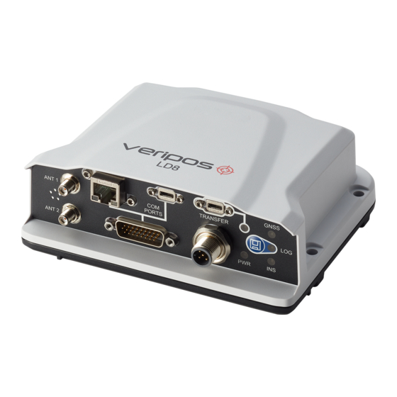
Hardware Overview 2.3 Interface Panel Connections This section details the antenna and data connectivity available from the LD8 interface panel. 2.3.1 Coaxial The LD8 interf ace panel is fitted with two SMA antenna connectors labelled ANT 1 and ANT 2: Interface panel of LD8 with two SMA antenna connectors •... -
Page 12: Ethernet And Webui Connection
Ethernet and WebUI Connection 3 Ethernet and WebUI Connection The LD8 supports Ethernet (10Base-T/100Base-TX) for configuration and interfacing to other vessel systems. The Ethernet port supports IPv4 Internet layer and TCP/IP transport. 3.1 Ethernet A PC or laptop with an Ethernet port and an up -to-date version of Microsoft Edge, Internet Explorer, Mozilla Firefox or Google Chrome is required to configure the LD8 for operation. -
Page 13: Configuration And Operation
Configuration and Operation 4 Configuration and Operation There are two ways in which the LD8 can be configured, by using VERIPOS Quantum software, or by using the LD8 WebUI. Quantum must be used if being used f or system monitoring. If Quantum is not available, system conf iguration must be performed through the WebUI, which features a terminal application that can be used for sending commands. - Page 14 Configuration and Operation 4.1.1 WebUI Status Page Items At the top of the page is a summary bar containing key system information. Below this, the main body of the LD8 WebUI Home > Status page is split into several boxes, with each box containing useful system information: Item Description Inf ormation relating to the operating mode, calculated position type, latitude, longitude,...
-
Page 15: L-Band Configuration
Configuration and Operation Acknowledgement Response When successfully making a configuration change a single or multiple line response containing ‘ <OK>’ can be expected. Rejection of Command A rejected command will be flagged as such with ‘INVALID MESSAGE’ or ‘ERROR’ appearing somewhere within the echoed response, or no response will be received. - Page 16 Configuration and Operation Where possible, different VERIPOS receiver units on the same vessel should be set to different beams to maximise redundancy. 4.2.1 Selecting Beam Via WebUI To select Auto Beam (or a single beam if required) navigate to Configuration > Positioning and click Receive (Rover), f ollowed by Next.
- Page 17 Configuration and Operation 4.2.5 Tracked L-band Beam and Signal Strength Status via Terminal The presently tracked L-band beam/s and signal strength/s can be found by entering: LOG LBANDTRACKSTAT The returned status will display information relating to any of the beams that are being actively tracked or searched f or.
-
Page 18: Activation And Deactivation Of Veripos Services
Configuration and Operation 4.3 Activation and Deactivation of VERIPOS Services To activate or deactivate VERIPOS services, firstly ensure that the LD8 is switched on and tracking an L-band beam with a healthy signal level (>36.5 dB). Tracking of a L-band beam is required as activation and deactivation updates are sent via the beam. -
Page 19: Calculation Configuration
Configuration and Operation 4.4 Calculation Configuration There are several calculation configuration options which can be changed by the use of commands. These conf iguration options can update the way in which VERIPOS service types are utilised. 4.4.1 PPP Mode Selection via Terminal The two PPP solutions that VERIPOS offer, Ultra and Apex, allow for decimetre accuracy positioning. - Page 20 Configuration and Operation 4.4.3 SBAS Configuration via Terminal The LD8 SBAS mode can be enabled or disabled via the terminal. The SBAS positioning mode can be enabled by entering: SBASCONTROL ENABLE AUTO The SBAS positioning mode can be disabled by entering: SBASCONTROL DISABLE 4.4.4 Heading Offset and Output Frequency Via WebUI The heading of fset and the heading output rate can be configured within the WebUI by navigating to...
-
Page 21: Ethernet Configuration
Configuration and Operation 4.5 Ethernet Configuration Network connectivity to the LD8 is essential f or configuration and implementing changes. The f ollowing sub- sections detail how to check and change the present IP address settings. 4.5.1 IP Configuration via WebUI IP addresses can be checked and configured by navigating to Settings >... - Page 22 Configuration and Operation 4.5.3 Setting a Static IP via Terminal The LD8 is preconfigured with a static IP of 192.168.2.8, however this IP address can be changed to a different static IP address. The command to change to a static IP follows the structure of: IPCONFIG [interface_name] [address_mode] [IP_address] [netmask] [gateway] Example for this: IPCONFIG ETHA STATIC 192.168.2.8 255.255.255.0 192.168.2.1...
-
Page 23: Output Configuration
Configuration and Operation 4.6 Output Configuration The LD8 is capable of outputting VERIPOS RTCM Message Command variable data and a selection of messages via serial port or GPGGA through TCP/IP. GPGST • Serial outputs for the three LD8 serial ports can GPZDA be ref erenced within commands as required by using ‘COM1’, ‘COM2’... - Page 24 Configuration and Operation 4.6.2 Specifying Baud Rate via WebUI To specify a baud rate for COM Ports 1, 2 or 3 navigate to Configuration > Ports click on the cog wheel within the Port f ield: A window will open that will allow f or a baud rate of 2400, 4800, 9600, 19200, 38400, 57600 or 115200 to be selected.
- Page 25 Configuration and Operation 4.6.4 Enabling Message Outputs via Terminal To enable a message, a single command must be sent for each message on each port. Message types can be output on COM 1-3 or ICOM 1-3. This, along with the message command variable, should be entered in the command line.
- Page 26 Configuration and Operation DQI Behavior Command Variable When the calculation is converged to a PPP service the DQI will report the value 2. When the calculation is converged to a PPP service the DQI will report the value 5. The below command example shows the behaviour of the DQI when converged for PPP to a value of 2. The highlighted area below is where the variable of 2 or 5 should be set: GGAQUALITY 4 OUT_OF_BOUNDS 2 WAAS 2 PPP 2 PSRDIFF 2 4.6.8 Setting Baud rates via Terminal...
-
Page 27: Input Configuration
Configuration and Operation 4.7 Input Configuration The LD8 is capable of utilising corrections f rom external sources of VERIPOS RTCM (RTCM v2, RTCM v3 or CMR) and RTK correction data. 4.7.1 Inputting External VERIPOS RTCM via Terminal To input external corrections, it is required to issue two commands to the unit. These two commands will configure the required baud rate of input and then set the port for decoding of VERIPOS RTCM data. -
Page 28: Rolling Log
Configuration and Operation 4.8 Rolling Log 4.8.1 Viewing Rolling Log via WebUI The LD8 is preconfigured to utilise a rolling data log. This data can be used to conduct various types of analysis or f or troubleshooting purposes by VERIPOS. From this data, RINEX observation logs can be generated, if required. -
Page 29: Factory Reset
Configuration and Operation 4.9 Factory Reset A f actory reset can be performed to revert the LD8 back to default factory settings. This should only be carried out under the advice of VERIPOS Support. 4.9.1 Factory Resetting via Terminal A f actory reset should be performed by issuing the case sensitive command: LUA START factoryreset.lua LD8 Operations Manual AB-V-MA-00635_RevA6... -
Page 30: Reference Information
Reference Information 5 Reference Information 5.1 Commands List Index Commands used within this manual are listed below. Text highlighted in red should be changed as required. Command Description The format for assigning a specific L-band ASSIGNLBANDBEAM beam Setting for automatically tracking L-band ASSIGNLBANDBEAM AUTO beams GGAQUALITY 4 OUT_OF_BOUNDS 2 WAAS 2 PPP... -
Page 31: Ld8 Output Sentences
Reference Information 5.2 LD8 Output Sentences This section outlines the message structure of the following message output types: • • • • • • • • • • • VERIPOS UKOOA 5.3 NMEA Talker IDs The NMEA talker identif ier serves to define the nature of the data being transmitted. The talker is the f irst 2 characters after the $ sign within the NMEA sentence. - Page 32 Reference Information 5.3.1 GGA Sentence The NMEA GGA sentence contains time and position fix related data for a GPS system. It includes basic quality information, which is limited to ‘Fix Quality’, ‘Number of Satellites in Use’, ‘HDOP’ and ‘Age of Corrections’.
- Page 33 Reference Information 5.3.2 GST Sentence The NMEA GST sentence provides error statistics of the position fix. These statistics follow from the position calculation process. GST Sentence Structure & Example $GNGST, hhmmss.ss, a.aa, b.bb, c.cc, d.dddd, e.ee, f .ff, g.gg *hh $GNGST, 024603.00, 1.47, 0.11, 0.07, 28.3688, 0.10, 0.08, 0.16 *58 GST Sentence Defined Field...
- Page 34 Reference Information 5.3.4 GSA Sentence The NMEA GSA sentence contains the GNSS receiver operating mode, active satellites used in the navigation solution, and DOP values. GSA Sentence Structure & Example $GNGSA, a, 1, cc, cc, cc, cc, cc, cc, cc, cc, cc, cc, cc, cc, d.d, e.e, f .f *hh $GNGSA, a, b, 02, 12, 15, 20, 21, 24, 25, 29, 32, , , 1.7, 0.9, 1.5 *58 GSA Sentence Defined...
- Page 35 Reference Information 5.3.6 GSV Sentence The NMEA GSV sentence provides information relating to the number of satellites (SV) in view, satellite ID numbers, elevation, azimuth, and SNR value in one sentence. GSV Sentence Structure & Example $GPGSV, a, b, cc, dd, ee, f ff, gg, dd, ee, f ff, gg, dd, ee, f ff, gg, dd, ee, f ff, gg, *hh, $GPGSV, 4, 1, 13, 02, 10, 043, 41, 05, 05, 103, 38, 10, 04, 238, 42, 12, 13, 030, 44, *7E, (Satellite 1) (Satellite 2)
- Page 36 Reference Information 5.3.8 GRS Sentences The NMEA GRS sentence provides range residuals for each satellite. GRS Sentence Structure & Example $GNGRS, hhmmss.ss, a, b.b, b.b, b.b, b.b, b.b, b.b, b.b, b.b, b.b, b.b, b.b, b.b, ,cc ,dd *67 $GNGRS, 142406.00, 1, -1.1, -0.1, 1.7, 1.2, -2.0, -1.3, 1.3, -0.4, -1.2, -0.2, , 1, 1, *hh GRS Sentence Defined Field...
- Page 37 Reference Information 5.3.9 RMC Sentences The NMEA RMC sentence provides essential GPS PVT (position, velocity, time) data. RMC Sentence Structure & Example $GNRMC, hhmmss.ss, a, ddmm.mmmmmmm, b, dddmm.mmmmmmm, c, dd.ddd, eee.e, ddmmyy f .f, g, h *hh $GNRMC, 143909, A, 5107.0020216, N, 11402.3294835, W, 0.036, 348.3, 210307, 0.0, E, D *31 RMC Sentence Defined...
- Page 38 Reference Information 5.3.11 VERIPOS UKOOA Sentences The VERIPOS UKOOA sentence is compliant with OGP 373-19 and IMCA S015 (July 2011). For further inf ormation relating to these standards please visit https://www.iogp.org and https://www.imca-int.com. VERIPOS UKOOA Sentence Structure & Example [ 240 7300 VERI 1 2067 295238.0 +0.1 +8.0 057 12.08207N 002 11.53776W 63.997 +50.40 1.151 0.564 1.004 7 0.025 0.054 0.14 0.001 0.000 0.000 0.003 0.06 0.05 6.5 P 15{ 20 27 13 30 26 8 21 16 7 10 15 85 77 75 86} 1{ 481}] VERIPOS UKOOA Sentence Defined...
- Page 39 Reference Information Field Content Notes be detected) and the Significance level used. The Variance and Covariance terms are elements from the variance-covariance 126…130 Unit Variance matrix of the position fix computation (un -scaled) in metres². 131…137 Variance Latitude 138…145 Covariance Lat/Long 146…152 Variance Longitude 153…159 Variance Height 95% Error Ellipse Semi...
-
Page 40: Contact Information
Contact Information 6 Contact Information All initial contacts regarding technical or support issues should be initially addressed to the VERIPOS Helpdesk. Where appropriate the Helpdesk will refer issues to the regional operations and engineering teams. 6.1 VERIPOS Helpdesk Details VERIPOS Online Support System (VOSS) http://help.veripos.com VERIPOS Support telephone +44 1224 965900... -
Page 41: Appendix
Appendix 7 Appendix 7.1 L-band Coverage Map LD8 Operations Manual AB-V-MA-00635_RevA6...
Need help?
Do you have a question about the veripos LD8 and is the answer not in the manual?
Questions and answers