Table of Contents
Advertisement
Advertisement
Table of Contents

Related Manuals for Hexagon Leica Nova TS60


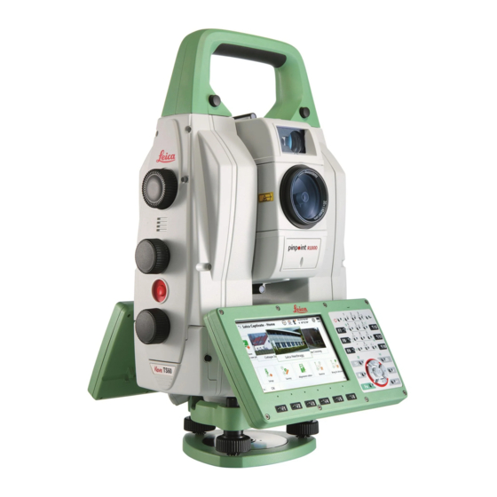
Summary of Contents for Hexagon Leica Nova TS60
- Page 1 Leica TS60/MS60/TM60 User Manual Version 4.0 English...
- Page 2 Introduction Purchase Congratulations on the purchase of the Leica TS60/MS60/TM60. This manual contains important safety directions as well as instructions for setting up the product and operating it. Refer to 1 Safety Directions for fur- ther information. Read carefully through the User Manual before you switch on the product. ☞...
- Page 3 Refer to the following resources for all MS60/TS60/TM60 documenta- tion/software: the Leica USB documentation card • https://myworld.leica-geosystems.com • Video tutorials are available on: http://www.leica-geosystems.com/captivate-howto Leica Geosystems On the last page of this manual, you can find the address of Leica Geosystems address book headquarters.
- Page 4 Service Description myDownloads Downloads of software, manuals, tools, training material and news for Leica Geosystems products.
-
Page 5: Table Of Contents
Table of Contents Safety Directions General Introduction Definition of Use Limits of Use Responsibilities Hazards of Use Laser Classification 1.6.1 General 1.6.2 Distancer, Measurements with Reflectors 1.6.3 Distancer, Measurements without Reflectors 1.6.4 Red Laser Pointer 1.6.5 Autofocus Capability of Telescope Camera 1.6.6 Automatic Target Aiming (ATRplus) 1.6.7... - Page 6 Combined Adjustment (l, t, i, c, ATRplus and Telescope Camera) Tilting Axis Adjustment (a) Adjusting the Circular Level of the Instrument and Tribrach Adjusting the Circular Level of the Prism Pole Inspecting the Laser Plummet of the Instrument Servicing the Tripod Care and Transport Transport Storage...
-
Page 7: Safety Directions
Safety Directions General Introduction Description The following directions enable the person responsible for the product, and the person who actually uses the equipment, to anticipate and avoid opera- tional hazards. The person responsible for the product must ensure that all users understand these directions and adhere to them. -
Page 8: Definition Of Use
Definition of Use Intended use Measuring horizontal and vertical angles • Measuring distances • Recording measurements • Capturing and recording images • Automatic target search, recognition and tracking • Visualising the aiming direction and vertical axis • Remote control of product •... -
Page 9: Hazards Of Use
Person responsible The person responsible for the product has the following duties: for the product To understand the safety instructions on the product and the instructions • in the User Manual To ensure that it is used in accordance with the instructions •... - Page 10 CAUTION Pointing product toward the sun Be careful when pointing the product toward the sun, because the telescope functions as a magnifying glass and can injure your eyes and/or cause damage inside the product. Precautions: ▶ Do not point the product directly at the sun. WARNING Distraction/loss of attention During dynamic applications, for example stakeout procedures, there is a...
- Page 11 WARNING Inappropriate mechanical influences to batteries During the transport, shipping or disposal of batteries it is possible for inap- propriate mechanical influences to constitute a fire hazard. Precautions: ▶ Before shipping the product or disposing it, discharge the batteries by the product until they are flat.
-
Page 12: Laser Classification
WARNING Improper disposal If the product is improperly disposed of, the following can happen: If polymer parts are burnt, poisonous gases are produced which may • impair health. If batteries are damaged or are heated strongly, they can explode and •... -
Page 13: Distancer, Measurements With Reflectors
1.6.2 Distancer, Measurements with Reflectors General The EDM module built into the product produces a visible laser beam which emerges from the telescope objective. The laser product described in this section is classified as laser class 1 in accordance with: IEC 60825-1 (2014-05): “Safety of laser products”... - Page 14 unintentional exposure would rarely reflect worst case conditions of (e.g.) beam alignment with the pupil, worst case accommodation, inherent safety margin in the maximum permissible exposure to laser radi- ation (MPE) natural aversion behaviour for exposure to bright light for the case of vis- ible radiation.
-
Page 15: Red Laser Pointer
Labelling A TS60/MS60 instrument is shown. 008674_001 Model: MS60 Art.No.: 123456 Equip.No.: 1234567 Power: 12-18V 40W max S.No.: Leica Geosystems AG 123456 CH-9435 Heerbrugg Manufactured: XX.20XX Made in Switzerland Complies with 21 CFR 1040.10 and 1040.11 except for conformance with IEC 60825-1 Ed. - Page 16 Description Value TS60 MS60 TM60 Maximum average radiant 4.8 mW 1.7 mW power Pulse duration 800 ps 1.5 ns Pulse repetition frequency 100 MHz 2 MHz (PRF) Beam divergance 0.2 mrad x 0.3 mrad 0.2 mrad x 0.3 mrad NOHD (Nominal Ocular Haz- 44 m / 144 ft 21 m / 69 ft ard Distance) @ 0.25s...
-
Page 17: Autofocus Capability Of Telescope Camera
Labelling A TS60/MS60 instrument is shown. 008674_001 1.6.5 Autofocus Capability of Telescope Camera General TS60/MS60/TM60 I contain a coaxial telescope camera with autofocus capabil- ity. When using the auto focus functions a visible laser beam may emerge from the telescope (depending on the focussing mode). The laser product described in this section is classified as laser class 1 in accordance with: IEC 60825-1 (2014-05): “Safety of laser products”... -
Page 18: Automatic Target Aiming (Atrplus)
A TS60/MS60 instrument is shown. Laser beam 008673_001 1.6.6 Automatic Target Aiming (ATRplus) General The Automatic Target Aiming built into the product produces an invisible laser beam which emerges from the telescope objective. The laser product described in this section is classified as laser class 1 in accordance with: IEC 60825-1 (2014-05): “Safety of laser products”... -
Page 19: Powersearch (Ps)
A TS60/MS60 instrument is shown. Laser beam 008673_001 1.6.7 PowerSearch (PS) This chapter is valid for TS60/MS60. ☞ General The PowerSearch built into the product produces an invisible laser beam which emerges from the front side of the telescope. The laser product described in this section is classified as laser class 1 in accordance with: IEC 60825-1 (2014-05): “Safety of laser products”... -
Page 20: Electronic Guide Light (Egl)
A TS60/MS60 instrument is shown. Laser beam 008678_001 1.6.8 Electronic Guide Light (EGL) This chapter is valid for TS60/MS60. ☞ General The Electronic Guide Light built into the product produces a visible LED beam which emerges from the front side of the telescope. ☞... -
Page 21: Autoheight Laser Plummet
These products are safe for momentary exposures but can be hazardous for deliberate staring into the beam. The beam may cause dazzle, flash-blindness and after-images, particularly under low ambient light conditions. Description Value Wavelength 640 nm Maximum average radiant power 0.95 mW Pulse duration 0.1 ms - cw... -
Page 22: Electromagnetic Compatibility (Emc)
Description Value Maximum average radiant power 0.95 mW Pulse duration <1 ns Pulse repetition frequency (PRF) 320 MHz Beam divergance <1.5 mrad CAUTION Class 2 laser product From a safety perspective, class 2 laser products are not inherently safe for the eyes. - Page 23 CAUTION Use of the product with accessories from other manufacturers. For example field computers, personal computers or other electronic equip- ment, non-standard cables or external batteries This may cause disturbances in other equipment. Precautions: ▶ Use only the equipment and accessories recommended by Leica Geosys- tems.
-
Page 24: Fcc Statement, Applicable In U
WARNING Use of product with radio or digital cellular phone devices Electromagnetic fields can cause disturbances in other equipment, in installa- tions, in medical devices, for example pacemakers or hearing aids and in air- crafts. Electromagnetic fields can also affect humans and animals. Precautions: ▶... - Page 25 Labelling MS60/TS60/ A TS60/MS60 instrument is shown. TM60 Model: MS60 Art.No.: 123456 Equip.No.: 1234567 Power: 12-18V 40W max S.No.: Leica Geosystems AG 123456 CH-9435 Heerbrugg Manufactured: XX.20XX Made in Switzerland Complies with 21 CFR 1040.10 and 1040.11 except for conformance with IEC 60825-1 Ed.
-
Page 26: Ised Statements (En/Fr), Applicable In Canada
ISED Statements (EN/FR), Applicable in Canada WARNING This Class (B) digital apparatus complies with Canadian ICES-003. Cet appareil numérique de la classe (B) est conforme à la norme NMB-003 du Canada. Canada Compliance Statement This device contains licence-exempt transmitter(s)/receiver(s) that comply with Innovation, Science and Economic Development Canada’s licence- exempt RSS(s). -
Page 27: Description Of The System
Description of the System System Components Main components MS60 / TS60 / TM60 CS20 CS35 008683_002 Component Description MS60/TS60/TM60 an instrument for measuring, calculating and • capturing data. comprised of various models with a range of • accuracy classes. integrated with an add-on GNSS system to form •... - Page 28 Term Description PinPoint PinPoint refers to the Reflectorless EDM technology which enables an increased measuring range with a smaller laser spot size. Two options are available: R1000 and R2000. Electronic Guide Light An EGL fitted to an instrument assists with prism targeting.
-
Page 29: System Concept
Term Description RadioHandle A component of remote mode is the RH16/RH17 RadioHandle. It is an instrument carry handle with an integrated radio modem with attached antenna. Communication side Communication side cover with integrated Bluetooth, cover SD card slot, USB port, WLAN and RadioHandle hot- shoe is standard for a MS60/TS60/TM60 instrument and a component of a SmartStation. -
Page 30: Power Concept
Software for Software type Description TS models TS firmware The Leica Captivate software is running on (xx.fw) the TS instrument and covers all functions of the instrument. The main applications and languages are integrated into the firmware and cannot be deleted. -
Page 31: Data Storage Concept
Model Power supply Externally by GEV219 cable and GEB371 battery. If an external power supply is connected and the internal battery is inserted, then the external power is used for the standard setting. It is pos- sible to configure the main power source to either internal battery or external power supply. -
Page 32: Container Contents
Container Contents Container for MS60/ TS60/TM60 and accessories 008684_001 Cover for eyepiece Cover for objective SD card and cover MS1 industrial 1 GB USB memory stick Counterweight for diagonal eyepiece Stylus Instrument with tribrach and standard handle or RadioHandle GFZ3 or GOK6 diagonal eyepiece Manuals and USB documentation card Protective cover for instrument, sunshade for objective lens and cleaning cloth... - Page 33 Container for GS SmartPole/ SmartStation and accessories - part 1 of 2 008616_003 GHT63 pole holder clamp Allen key and adjustment tool GAD33 antenna arm CS35 tablet or CS20 field controller with GHT66 holder GAD108 antenna arm Manuals and USB documentation card GPR121 circular prism PRO or GZT4 target plate for GPH1 and GPH1 prism holder with GPR1 circular prism GAD109 QN-TNC Adapter...
- Page 34 Container for GS SmartPole/ SmartStation and accessories - part 2 of 2 008617_002 Cables GRZ101 mini prism and GAD103 adapter GAT1 or GAT2 radio antennas GKL311 charger GRZ4 or GRZ122 prism Standard handle or RadioHandle GAD110 adapter for antenna GAD31 screw to stub adapter Mini prism spike GMP101 mini prism Container for TS...
-
Page 35: Instrument Components
Manuals and USB documentation card GAT25 radio antenna Mini prism spike GRZ4 or GRZ122 prism SD card and cover Adjustment tool and allen key GRZ101 mini prism and GAD103 adapter GEB331 battery GHT63 pole holder clamp Tip for mini pole GLI115 clip-on bubble for GLS115 mini prism pole CS20 field controller and GHT66 holder Stylus... - Page 36 Communication Side Cover Compartment lid SD card port USB host port for USB stick 008687_002 Instrument components for SmartStation GS16 SmartAntenna GAD110 SmartAntenna Adapter Communication side cover 008688_003 Instrument components for remote mode RadioHandle Communication side cover 008689_001 Description of the System...
-
Page 37: User Interface
User Interface Keyboard Keyboard Function keys F1-F6 MS60/TS60/TM60 Function keys F7-F12 ON/OFF Alphanumeric keys Backspace Home Arrow keys 0008626_002 Enter Favourites Camera Keys Function Function Correspond to six softkeys that appear on keys the bottom of the screen when the screen is F1 to F6 activated. -
Page 38: Operating Principles
Function Selects the highlighted line and leads to the next logical menu / dialog. Starts the edit mode for editable fields. Opens a selectable list. Backspace Deletes the job in the centre of the job carousel. Key combinations Function Hold Fn while pressing Switch to Windows. -
Page 39: Autofocus Capability Of Telescope Camera
Operation Description To start the edit mode in editable Tap on the editable field. fields To highlight an item or parts of it for Drag the supplied stylus from the editing left to the right. To accept data entered into an edit- Tap on the screen outside of the able field and exit the edit mode editable field. -
Page 40: Operation
Operation Setting Up the TS Instrument Instrument setup step-by-step 008690_001 Shield the instrument from direct sunlight and avoid uneven temper- ☞ atures around the instrument. Extend the tripod legs to allow for a comfortable working posture. Position the tripod above the marked ground point, centring it as good as possible. -
Page 41: Setting Up Smartstation
Setting Up SmartStation SmartStation Setup step-by-step 008691_001 Place the GAD110 adapter for the GS16 antenna onto the instru- ment by simultaneously pressing and holding-in the four push but- tons. Ensure that the interface connection on the underside of the ☞ adapter is on the same side as the Communication side cover. -
Page 42: Setting Up Smartpole
Setting Up SmartPole SmartPole Setup GS18 antenna using GS16/GS18 GS16 antenna RTK slot-in device 360° prism Field controller on GHT66 holder (Alternative, not illustrated: tablet on GHT78 holder) GHT63 clamp GLS31 pole with snap-lock positions RH16/RH17 RadioHandle Instrument Communication side cover, 008693_003 integrated Tripod... -
Page 43: Fixing The Field Controller To A Holder And Pole
Mounting base radio The GHT43 tripod adapter is used to mount the TCPS29 to all Leica to tripod step-by- standard tripods, and to optimise the radio transmission perform- step ance. Attach the TCPS29 to the adapter and then attach the adapter to the tripod leg. - Page 44 Before placing the CS field controller onto the mounting plate, ensure that the locking pin is put into the unlocked position. To unlock the locking pin, push the locking pin to the left. 008546_001 Hold the CS field controller above the holder and lower the end of the CS field controller into the mounting plate.
-
Page 45: Fixing The Cs35 Tablet To A Holder And Pole
Fixing the CS35 Tablet to a Holder and Pole Components of For fixing the CS35 tablet to a pole you need the following components: GHT63 clamp and GHT63 clamp GHT78 holder Plastic sleeve Pole clamp Clamp bolt GHT78 holder Locking lever Mounting arm Mounting brackets 009241_001... -
Page 46: Connecting To A Personal Computer
009248_001 After placing the tablet onto the mounting plate, set the locking lever to the locked position (see illustration). Detaching the tablet from the holder/pole step-by-step 009249_001 Set the locking lever of the GHT78 holder to the unlocked position. 009250_001 Lift the right side of the tablet and slide the tablet to the right and out of the holder. - Page 47 Connect your instrument to the PC via cable. On your PC, select to Control Panel > Device Manager. In Network Adapters, right-click on Remote NDIS based LGS…. Click on Uninstall. Set Delete the driver… as checked. Press OK. Install Leica USB Start the PC.
- Page 48 Click Next>. The Ready to Install the Program window appears. Click Install. The drivers will be installed on your PC. The InstallShield Wizard Completed window appears. Click Finish to exit the wizard. Connect to PC via USB Start the PC. cable step-by-step Plug the cable into the instrument.
-
Page 49: Power Functions
A file browser opens. You can now browse within the folders on the instrument. Power Functions Turning the Press and hold power key ( ) for 2s. instrument on The instrument must have a power supply. ☞ Turning the Press and hold power key ( ) for 2 s. -
Page 50: Batteries
4.10 Batteries 4.10.1 Operating Principles First-time use/ The battery must be charged before using it for the first time because it is • charging batteries delivered with an energy content as low as possible The permissible temperature range for charging is from 0 °C to •... -
Page 51: Working With The Memory Device
Place the battery into the battery housing, ensuring that the con- tacts are facing outward. Click the battery into position. Place the battery housing into the battery compartment. Push the battery housing in until it fits completely into the battery compart- ment. -
Page 52: Led Indicators
Insert and remove a USB stick step-by- step 008699_001 ☞ The USB stick is inserted into the USB host port inside the Commu- nication side cover of the instrument. Press the button on the side of the Communication side cover to unlock the communication compartment. -
Page 53: Guidelines For Correct Results
IF the THEN Link LED no radio link to field controller. radio link to field controller. Data Transfer no data transfer to/from field controller. green or data transfer to/from field controller. green flashing Mode LED data mode. configuration mode. 4.13 Guidelines for Correct Results Distance measurement... - Page 54 Do not measure with two instruments to the same target simultaneously to ☞ avoid getting mixed return signals. ATRplus/Lock Instruments equipped with an ATRplus sensor permit automatic angle and dis- tance measurements to prisms. The prism is sighted with the optical sight. After initiating a distance measurement, the instrument sights the prism centre automatically.
-
Page 55: Check & Adjust
Check & Adjust Overview Description Leica Geosystems instruments are manufactured, assembled and adjusted to the best possible quality. Quick temperature changes, shock or stress can cause deviations and decrease the instrument accuracy. It is therefore recom- mended to check and adjust the instrument from time to time. This check and adjust can be done in the field by running through specific measurement pro- cedures. -
Page 56: Preparation
During the manufacturing process, the instrument errors are carefully determ- ☞ ined and set to zero. As mentioned above, these errors can change and it is highly recommended to redetermine them in the following situations: Before the first use • Before every high precision survey •... -
Page 57: Combined Adjustment (L, T, I, C, Atrplus And Telescope Camera)
completed. This outcome is a normal effect. To speed up the ATRplus meas- urement, the telescope is normally not positioned exactly on the centre of the prism. These small deviations ATRplus offsets, are calculated individually for each measurement and corrected electronically. This means that the hori- zontal and vertical angles are corrected twice: first by the determined ATRplus errors for Hz and V, and then by the individual small deviations of the current aiming. - Page 58 Face I measurement If Calibrate the automatic target aiming is checked and an ATRplus is available, the adjustment will include the determination of the ATRplus Hz and V adjustment errors. ☞ Use a clean Leica standard prism as the target. Do not use a 360°...
-
Page 59: Tilting Axis Adjustment (A)
Adjustment Status Number of measurements: Shows the number of runs completed. One run consists of a measurement in face I and face II. l Component quality (1 σ): and similar lines show the standard deviations of the determined adjustment errors. The standard devi- ations can be calculated from the second run onwards. - Page 60 Face I measurement Aim the telescope accurately at a target at about 100 m dis- tance (or at least 20 m). The target must be positioned at least 27°/30 gon above or beneath the horizontal plane. + 27° - 27° 008703_001 Measure to measure and to continue to the next screen.
-
Page 61: Adjusting The Circular Level Of The Instrument And Tribrach
Select Finish to accept the results. No more runs can be added later. Select Redo to decline all measurements and to repeat all calibra- tion runs. Next step IF the results are THEN to be stored Next overwrites the old tilting axis error with the new one. -
Page 62: Adjusting The Circular Level Of The Prism Pole
☞ After the adjustments, all adjusting screws must have the same tightening tension and no adjusting screw should be loose. Adjusting the Circular Level of the Prism Pole Adjusting the circular Suspend a plumb line. level step-by-step Use a pole bipod, to align the prism pole parallel to the plumb line. -
Page 63: Servicing The Tripod
The laser plummet is switched on when the Level & Compensator screen is entered. Adjust the laser plummet intensity. Inspection of the laser plummet should be carried out on a bright, smooth and horizontal surface, like a sheet of paper. Mark the centre of the red dot on the ground. -
Page 64: Care And Transport
Care and Transport Transport Transport in the field When transporting the equipment in the field, always make sure that you either carry the product in its original container, • or carry the tripod with its legs splayed across your shoulder, keeping the •... -
Page 65: Cleaning And Drying
Cleaning and Drying Product and accessor- Blow dust off lenses and prisms. • Never touch the glass with your fingers. • Use only a clean, soft, lint-free cloth for cleaning. If necessary, moisten • the cloth with water or pure alcohol. Do not use other liquids; these may attack the polymer components. -
Page 66: Technical Data
Technical Data Angle Measurement Accuracy Type Standard deviation Display least count Hz, V ISO 17123-3 ["] [mgon] ["] [mgon] TM60 R1000/ 0.15 0.01 TM60 I R1000 0.30 0.01 TS60 R1000 0.15 0.01 MS60 R2000 0.30 0.01 Characteristics Absolute, continuous, diametric. Distance Measurement with Reflectors Range For TS60/TM60 - R1000:... - Page 67 Reflector Range A Range B Range C [ft] [ft] [ft] Mini prism 1200 4000 1800 6000 3000 10500 (GMP101) Reflector tape 1200 1200 (GZM31) 60 mm x 60 mm Machine Automa- 1200 4000 2250 7500 3000 10500 tion power prism (MPR122) ☞...
-
Page 68: Distance Measurement Without Reflectors
Distance Standard Standard Measurement measuring deviation deviation time, typical [s] mode ISO 17123-4, ISO 17123-4, standard prism tape* Standard 1 mm + 1.5 ppm 1 mm + 1.5 ppm Fast 2 mm + 1.5 ppm 3 mm + 1.5 ppm Continuously 2 mm + 1.5 ppm 3 mm + 1.5 ppm... -
Page 69: Distance Measurement - Long Range (Lo Mode)
Range Description Underground, night and twilight Accuracy For TS60/TM60 - R1000: Standard Standard Measure time, Measure time, measuring deviation typical [s] maximum [s] ISO 17123-4 0 m - 500 m 2 mm + 2 ppm >500 m 4 mm + 2 ppm Object in shade, sky overcast. -
Page 70: Automatic Target Aiming (Atrplus)
Display unambiguous: up to 12000 m Atmospheric condi- Range Description tions Strong haze, visibility 5 km; or strong sunlight, severe heat shimmer Light haze, visibility about 20 km; or moderate sun- light, slight heat shimmer Overcast, no haze, visibility about 40 km; no heat shimmer Accuracy Standard... - Page 71 Prism Range (Target Aiming) Range (Target Locking) [ft] [ft] ☞ The maximum range depends on the atmospheric condition. Rain, strong sunlight or severe heat shimmer can decrease the max- imum range. Shortest measuring distance: 360° prism (Target aiming): 1.5 m Shortest measuring distance: 360°...
-
Page 72: Scanning
Type Direction of prism movement Tangential Radial Prism Lock with 8 m/s at 20 m 11 m/s Measure distance: Continuously A tangential movement means the prism is passing by the instrument ☞ at the specified distance. A radial movement means the prism is moving away from or towards the instrument in the line of sight direction. -
Page 73: Powersearch (Ps)
Accuracy Range noise* (1 sigma; Kodak Grey Card (Albedo 90%)): Distance 30 kHz 8 kHz 1000 Hz 1 Hz 10 m 2.0 mm 1.0 mm 0.6 mm 0.4 mm 25 m 2.2 mm 1.2 mm 0.8 mm 0.5 mm 50 m 3.0 mm 1.5 mm 1.0 mm... -
Page 74: Loc8 Theft Deterrence And Location Device (Optional)
Searching Type Value Typical search time 5 - 10 s Rotating speed up to 100 gon/s Default search area Hz: 400 gon, V: 40 gon Definable search windows Characteristics Type Description Principle Digital signal processing Type Infrared laser LOC8 Theft Deterrence and Location Device (optional) Internal battery Battery Voltage... -
Page 75: Smartstation
Type Value Focal length At ¥ 231 mm Field of view 1.5° diagonal Frame rate ≤20 frames per second Focus Servofocus: Manual motorised focus, avail- able for all variants instrument types Autofocus: Automatic focusing, available for instruments with imaging functionality Time to focus Typical 2 s Focus range... -
Page 76: Smartstation Dimensions
Leica, Leica 4G, CMR, CMR+, RTCM 2.2, 2.3, 3.0, 3.1, 3.2 MSM 7.11.2 SmartStation Dimensions SmartStation 190 mm dimensions 248 mm 124 mm 124 mm 248 mm 008709_001 7.12 Conformity to National Regulations 7.12.1 TS60/MS60/TM60 WARNING This equipment has been tested and found to comply with the limits for a Class B digital device, pursuant to part 15 of the FCC rules. -
Page 77: Radiohandle
The conformity for countries with other national regulations not • covered by the FCC part 15, 22 and 24 or European Direct- ive 2014/53/EU has to be approved prior to use and operation. Japanese Radio Law and Japanese Telecommunications Business Law •... -
Page 78: Loc8 Theft Deterrence And Location Device (Optional)
Conformity to Hereby, Leica Geosystems AG declares that the radio equipment type • national regulations RadioHandle is in compliance with Directive 2014/53/EU and other applicable European Directives. The full text of the EU declaration of conformity is available at the fol- lowing Internet address: http://www.leica-geosystems.com/ce. -
Page 79: Dangerous Goods Regulations
Type Value WCDMA WCDMA 900: 880 - 960 MHz WCDMA 2100: 1920 - 2170 MHz WLAN 2.4G Wi-Fi 802.11 b/g/n (20 MHz): 2412 - 2472 MHz 802.11 n (40 MHz): 2422 ~ 2462 MHz 1.57542 GHz Output power Type Value GPRS: Maximal power: 29,13 dBm WCDMA... - Page 80 Therefore, the overall pointing accuracy of the determined point location can be lower than the given angular accuracy and the ATRplus accuracy. The following paragraphs provide a short overview of these influencing factors and their possible intensities. Angular accuracy The accuracy of angular measurements depends on the instrument type. The angular accuracy for total stations is typically in the range from 0.5²...
- Page 81 Refer to the white paper "Leica Surveying Reflectors" for information ☞ about the different centring accuracies. More influencing factors When determining absolute coordinates, the following parameters can also affect the resulting accuracy: Environmental conditions: temperature, air pressure and humidity • Typical instrument errors, such as horizontal collimation error or index •...
- Page 82 Instrument ports Name Description Serial/USB 8 pin LEMO-1 for power, communica- • tion, data transfer. This port is located at the base of the • instrument. RadioHandle Hotshoe connection for RadioHandle • with Remote Mode and SmartAntenna Adapter with SmartStation. This port is located on top of the Com- •...
- Page 83 With RH16/RH17 72 mm 248 mm 124 mm 124 mm 248 mm 008710_001 Weight Type MS60/TS60 TM60 Instrument without battery 7.27 kg 6.8 kg Tribrach 0.8 kg 0.8 kg Internal battery 0.43 kg 0.43 kg Recording Data can be recorded onto an SD card or into internal memory. Type Capacity [MB] Number of measurements...
- Page 84 ☞ Avoid line-of-sight obstructions. The full spot needs to be on target. For best performance use the new Leica tripods. For older tripods, ☞ an upgrade of the screw is recommended. Laser plummet Type Value Type Visible red laser class 2 Location In standing axis of instrument Accuracy...
- Page 85 Protection against water, dust and sand Type Protection All types IP65 (IEC60529) / MIL-STD-810G, Methods 506.5 I and 507.5 Humidity Type Protection All types Max 95 % non condensing The effects of condensation are to be effectively counterac- ted by periodically drying out the instrument. Reflectors Type Additive...
-
Page 86: Scale Correction
7.14 Scale Correction Use of scale By entering a scale correction, reductions proportional to distance can be correction taken into account. Atmospheric correction. • Reduction to mean sea level. • Projection distortion. • Atmospheric correc- The slope distance displayed is correct if the scale correction in ppm, mm/km, tion DD1 which has been entered corresponds to the atmospheric conditions prevailing at the time of the measurement. - Page 87 Formulas Formula for visible red laser 0.29535 · p 4.126 · 10 · h ΔD = 286.338 - · 10 002419_002 Atmospheric correction [ppm] Air pressure [mbar] Air temperature [°C] Relative humidity [%] 273.15 (7.5 * t/(237.3 + t)) + 0.7857 If the basic value of 60 % relative humidity as used by the EDM is retained, the maximum possible error in the calculated atmospheric correction is 2 ppm, 2 mm/km.
- Page 88 Atmospheric Atmospheric corrections in ppm with temperature [°C], air pressure [mb] and corrections °C height [m] at 60% relative humidity. 550 mb 1000 1050 mb 50°C 50°C 40°C 40°C 30°C 30°C 20°C 20°C 10°C 10°C 0°C 0°C -10°C -10°C -20°C -20°C 550 mb 1000 1050 mb...
-
Page 89: Reduction Formulas
7.15 Reduction Formulas Formulas Mean Sea Level Instrument Reflector Slope distance Horizontal distance Height difference TS_110 The instrument calculates the slope distance, horizontal distance, height dif- ference in accordance with the following formulas: = D 0 · ( 1 + ppm · 10 ) + AC 002425_002 Displayed slope distance [m]... - Page 90 Formulas Mean Sea Level Instrument Reflector Slope distance Horizontal distance Height difference TS_110 The instrument calculates the slope distance, horizontal distance, height dif- ference in accordance with the following formulas: = D 0 · ( 1 + ppm · 10 ) + AC 002425_002 Displayed slope distance [m]...
- Page 91 · ∑ D i = 1 TS_114 Slope distance as arithmetic mean of all measurements å Single slope distance measurement Number of measurements ∑ ∑ ∑ - D) i = 1 i = 1 i = 1 n - 1 n - 1 TS_115 Standard deviation of a single slope distance measurement...
-
Page 92: Software Licence Agreement/Warranty
Software Licence Agreement/Warranty Software Licence This product contains software that is preinstalled on the product, or that is Agreement supplied to you on a data carrier medium, or that can be downloaded by you online according to prior authorisation from Leica Geosystems. Such software is protected by copyright and other laws and its use is defined and regulated by the Leica Geosystems Software Licence Agreement, which covers aspects such as, but not limited to, Scope of the Licence, Warranty, Intellectual Prop-... - Page 94 819179-4.0.0en Original text (819179-4.0.0en) Published in Switzerland © 2020 Leica Geosystems AG, Heerbrugg, Switzerland Leica Geosystems AG Heinrich-Wild-Strasse CH-9435 Heerbrugg Switzerland Phone +41 71 727 31 31 www.leica-geosystems.com...
Need help?
Do you have a question about the Leica Nova TS60 and is the answer not in the manual?
Questions and answers