Hexagon Veripos LD8 Installation Manual
Hide thumbs
Also See for Veripos LD8:
- Operation manual (63 pages) ,
- Installation manual (30 pages) ,
- Quick start manual (2 pages)
Table of Contents
Advertisement
Quick Links
Advertisement
Table of Contents

Related Manuals for Hexagon Veripos LD8


Summary of Contents for Hexagon Veripos LD8
- Page 1 Installation Manual AB-V-MA-00634_RevA7 02 August 2023...
-
Page 2: Table Of Contents
Contents 1 Introduction 1.1 Scope 1.2 VERIPOS Support 1.3 Terms and abbreviations 1.4 Equipment care 1.5 Document conventions 1.6 LD8 Notices 1.7 Disclaimer 2 LD8 system 2.1 System overview 2.2 Connectors, LEDs and I/O ports 3 LD8 installation 3.1 LD8 schematic example 3.2 Location guidelines 3.3 Mounting 3.4 Ventilation requirements... -
Page 3: Introduction
Antenna and Coaxial Cable Installation LD8 FAQs Quick Guides, available from https://help.veripos.com. 1.1 Scope This installation manual provides the information necessary to install the Hexagon | VERIPOS LD8 receiver and covers these key aspects: Antenna installation Coaxial cabling DC Power requirements... -
Page 4: Terms And Abbreviations
1 Introduction 1.3 Terms and abbreviations Alternating Current AltBOC Alternative BOC modulation APEX VERIPOS high accuracy positioning solution Antenna Reference Point BEIDOU Chinese GNSS Binary Offset Carrier Bayonet Neill–Concelman Computed Minus Observed Controller Area Network Centimetre Clear to Send Decibel Direct Current Data Communications Equipment DGPS... - Page 5 1 Introduction RJ45 A physical network interface standard used in telecommunications Real-time Kinematic Request to Send SAL M12 Sensor Actor Line SBAS Satellite Based Augmentation System Sub-Miniature version A Transmission Control Protocol A threaded type of RF coaxial connector UART Universal Asynchronous Receiver-Transmitter User Interface Ultra...
-
Page 6: Equipment Care
1 Introduction 1.4 Equipment care This section summarizes safety guidelines when installing the LD8 unit. 1.4.1 Unpacking and inspection Carefully unpack and inspect the unit. If the equipment appears damaged, then return it using the original packaging. Responsibility for damage will not be accepted if the approved packaging is not used. Ensure all the major items and the ancillary equipment are supplied. -
Page 7: Document Conventions
1 Introduction 1.5 Document conventions 1.5.1 Typographical conventions Italic or bold text is used to emphasize certain information. Italic is also used in cross-references to other parts of the document and to other documents. Bold text is also used for indicators and touch screen “push-buttons” commands. Blue text is used for hyperlinking to other sections within this document or to external documents or websites. -
Page 8: Ld8 Notices
1 Introduction 1.6 LD8 Notices The following notices apply to the LD8: 1.6.1 Waste electrical and electronic equipment The Waste Electrical and Electronic Equipment Directive (hereinafter referred to as the “WEEE directive”) places an obligation on EU-based manufacturers, distributors, retailers and importers to take- back electronics products at the end of their useful life. - Page 9 1 Introduction 1.6.2 FCC This device complies with part 15 of the FCC Rules. Operation is subject to the following two conditions: (1) this device may not cause harmful interference, and (2) this device must accept any interference received, including interference that may cause undesired operation. LD8 has been tested and found to comply with the radiated and conducted emission limits for a Class B digital device.
- Page 10 1 Introduction 1.6.3 European Union / United Kingdom (UK) 1.6.3.1 Radio Equipment Directive VERIPOS declares that the LD8 including its Wi-Fi transceiver is in compliance with: 1. EU Directive 2014/53/EU 2. UK Regulations S.1. 2017/1206 The full text of either the UK or EU Declaration of Conformity may be obtained from VERIPOS upon request.
-
Page 11: Disclaimer
Nothing herein constitutes a binding obligation on Hexagon. The information contained herein is subject to change without notice. © Copyright 2023 Hexagon AB and/or its subsidiaries and affiliates. All rights reserved. A list of entities within the Hexagon Autonomy & Positioning division is available at https://hexagon.com/company/divisions/autonomy-and-positioning. -
Page 12: Ld8 System
2 LD8 system 2 LD8 system This section provides an outline description of the VERIPOS LD8 receiver including details on the different connectors, LED indicators and also lists information on the internal GNSS receiver. 2.1 System overview The LD8 is a high precision system, built into a lightweight, compact and environmentally protected enclosure and designed to operate reliably in the most demanding of marine environments. -
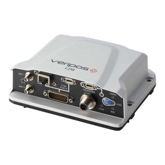
Page 13: Connectors, Leds And I/O Ports
2 LD8 system 2.2 Connectors, LEDs and I/O ports The LD8 can communicate with other devices, using serial or Ethernet ports. 2.2.1 Interface panel The LD8 interface panel has several connectors for interfacing with the unit: 2.2.2 Connector types Connector Connector Label Description... - Page 14 2 LD8 system 2.2.3 LEDs There are five LED indicators used to communicate the receiver status to the user: Description 1. TRANSFER Not currently supported Indicates the position status of 2. GNSS the receiver. Indicates the status of logging 3. LOG to the receiver internal memory 4.
- Page 15 2 LD8 system CAUTION The supply must be capable of providing enough current to operate the LD8, including the initial inrush transient. The AC / DC power adapter should be protected with a 6 Amp fuse. The DC supply can be current limited to 6 Amp with an external fuse.
-
Page 16: Ld8 Installation
3 LD8 installation 3 LD8 installation This section provides guidance on the installation of the LD8 receiver. In the event of difficulty contact your supplier or VERIPOS (https://help.veripos.com). 3.1 LD8 schematic example The schematic shown below is one example of an antenna setup arrangement. Please be aware that other antenna configurations are possible. -
Page 17: Location Guidelines
3 LD8 installation 3.2 Location guidelines When choosing installation locations, the following requirements should be taken under consideration: 1. Ensure adequate ventilation for free air flow to the main unit. This is especially important when working in hot or humid conditions. See section Ventilation Requirements for more details. 2. -
Page 18: Ventilation Requirements
3 LD8 installation 3.4 Ventilation requirements The LD8 needs 15-25mm clearance all-round to allow an adequate flow of air: 3.5 Antenna installation This section provides general guidance on installation of antennas and cabling. It is very important to the on-going performance of your system that a high-quality installation is performed, as this will ensure optimum performance and reliability. - Page 19 3 LD8 installation Examples of good installations – Antennas placed at top of mast with good spacing During installation observe the following guidelines: Offsets to the GNSS antennas must be measured carefully to ensure that no errors are introduced to the DP, Survey or Navigation systems. Care must be taken to ensure that antennas are not installed in the direct path of transmissions from vessel radar, Inmarsat systems, VSAT systems or high-power HF (whip/wire antennas).
- Page 20 3 LD8 installation 3.5.2 Placement for heading antennas Careful consideration for the placement of the primary and secondary antennas is required to maximise the LD8 GNSS heading accuracy. 3.5.2.1 Antenna separation The GNSS heading solution accuracy is largely determined by the distance (or baseline) between the primary and secondary antennas.
- Page 21 3 LD8 installation Assuming the antennas are mounted along the vessel centreline, with ANT 1 being the furthest forward antenna, the GNSS heading would closely reflect the vessel heading. In the below example, a small heading alignment correction would need to be applied in the navigation system software. In the next example, Antenna 1 and Antenna 2 are installed perpendicular to vessel North with the Antenna 1 at the Starboard side and Antenna 2 at the Port side.
-
Page 22: Coaxial Cable Installation
3 LD8 installation Antenna 1 and Antenna 2 should be installed at similar heights to ensure consistent heading. If this is not done the heading solution will be noisy, due to each antenna being subject to different amounts of vessel motion (such as vessel roll): The effect of vessel motion when antennas (blue) are mounted at different heights 3.6 Coaxial cable installation... - Page 23 3 LD8 installation 3.6.2 General cable guidance The VERIPOS recommended cable for the antenna runs is LMR-400. It is highly recommended that LMR-240 (thinner and more flexible) terminated tails are used at both ends of the LMR-400 cable to ease the attachment to antennas and receiver RF connectors.
-
Page 24: Antennas
3 LD8 installation Typical cable installation in a bridge mast area 3.7 Antennas This section details the antenna connections made to the LD8. 3.7.1 Coaxial cables to antennas The LD8 contains a GNSS receiver capable of tracking L-band. Additionally, a GNSS antenna is required to be connected to Antenna 2 for computation of a valid GNSS heading. -
Page 25: Reference Information
4 Reference information 4 Reference information 4.1 Technical specifications 4.1.1 Dimensions in mm 4.1.2 Mechanical specifications The LD8 is sealed to the IPX7, IP6X & IP67 specifications. Equipment complies with EN60945 Protected Equipment - 4th Edition. 4.1.3 Compass safe distance Conforms to IEC 60945. - Page 26 4 Reference information 4.1.5 Safety considerations Though the test conditions for the LD8 unit provide for a maximum operating temperature of +75 °C, continuous operation of all electronic components should, if possible, take place at ambient temperatures of only +25 °C. 4.1.6 Electrical specifications Voltage: +9 to +36 VDC...
-
Page 27: Cabling And Connectors
4 Reference information 4.2 Cabling and connectors 4.2.1 Power cable J1 pinout M12 Label on lead -VIN +VIN_A +VIN_B -VIN Chassis GND 4.2.2 High Density 26 Pin D-Type connector Description Function RS232 RS422 COM1 COM1 COM1 COM1 COM2 COM2 COM3 COM2 COM2 COM3... - Page 28 4 Reference information 4.2.3 I/O cable The interfacing cable connects to the high density 26 pin D-type connector which splits to three 9 pin D- type connectors (female) and a BNC female. The three comport connectors are configured as standard RS232 9-pin connections (DCE).
-
Page 29: Contact Information
All initial contacts regarding technical or support issues should be initially addressed to the VERIPOS Support. Where appropriate Support will refer issues to the regional operations and engineering teams. 5.1 VERIPOS Support Details VERIPOS Support website https://veripos.com/support VERIPOS Support telephone +44 1224 965900 VERIPOS Support e-mail support.veripos@hexagon.com LD8 Installation Manual... -
Page 30: Appendix
6 Appendix 6 Appendix 6.1 Summary specification of antennas 6.1.1 VERIPOS V560 combined GNSS & L-band antenna L-band/GPS/GLONASS: 1525-1610 MHz GPS L2/GLONASS L2: 1160-1252 MHz (complete with a narrow band filter for interference rejection) LNA Gain: 45db DC Voltage input: 3.0 to 15.0V RF Input Connector: TNC female (note cable RF connector –... -
Page 31: Summary Specification Of Cabling
6 Appendix The table below details the North, East and Up phase centre values for GNSS L1 and L2 frequencies: Relative to Antenna Reference Point (ARP) GNSS Frequency North (mm) East (mm) Up (mm) -0.34 -0.53 58.24 0.11 -0.76 68.35 6.2 Summary specification of cabling With the system VERIPOS typically provide pre-terminated cables and tails for use with both L-band and GNSS antennas (see the Delivery note). - Page 32 6 Appendix Performance property Units (metric) Weight lb/ft (kg/m) 0.068 (0.10) Tensile strength lb (kg) (72.6) Flat plate crush lb/in. (kg/mm) 40 (0.71) 6.2.1.3 Environmental specifications Performance property °F °C Installation temperature range -40 to +185 -40 to +85 Storage temperature range -94 to +185 -70 to +85 Operating temperature range...
- Page 33 6 Appendix Performance property Units (metric) Weight lb/ft (kg/m) 0.034 (0.05) Tensile strength lb (kg) (36.3) Flat plate crush lb/in. (kg/mm) 20 (0.36) 6.2.2.3 Environmental specifications Performance property °F °C Installation temperature range -40 to +185 -40 to +85 Storage temperature range -94 to +185 -70 to +85 Operating temperature range...
Need help?
Do you have a question about the Veripos LD8 and is the answer not in the manual?
Questions and answers