Graco Viscount I PLUS Instructions-Parts List Manual
Hydraulic motor
Hide thumbs
Also See for Viscount I PLUS:
- Instructions-parts list manual (30 pages) ,
- Instructions-parts list manual (21 pages)
Advertisement
Quick Links
Instructions – Parts List
Viscountr I Hydraulic Motor
Used as hydraulic drive for reciprocating pumps.
1500 psi (10 MPa, 102 bar) Maximum Hydraulic Input Pressure
Parts 236417, Series A, and 261466, Series A
Hydraulic Motor
Parts 236418, Series C, and 253608, Series A,
Hydraulic Reciprocator
US and Foreign Patents Pending
See also Manual 311211, High–Flo
Important Safety Instructions
Read all warnings and instructions in this manual.
Save these instructions.
See page 22 for maximum working pressures.
GRACO INC. P.O. BOX 1441 MINNEAPOLIS, MN 55440-1441
Copyright 1994, Graco Inc. is registered to I.S. EN ISO 9001
PLUS
R
Pumps
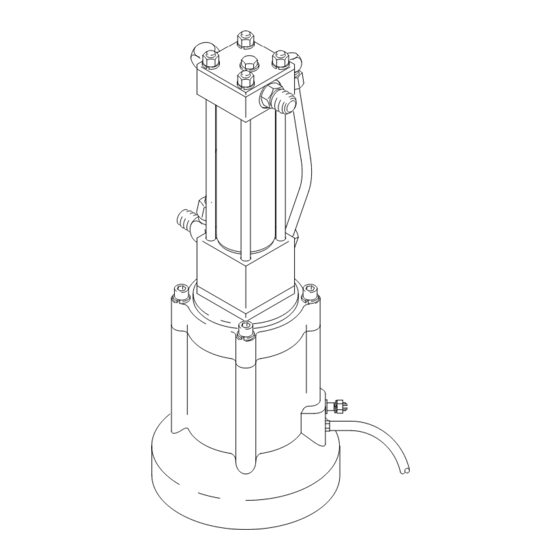
236417 Motor Shown
308330F
03054
Advertisement

Related Manuals for Graco Viscount I PLUS


Summary of Contents for Graco Viscount I PLUS
- Page 1 Read all warnings and instructions in this manual. Save these instructions. See page 22 for maximum working pressures. 236417 Motor Shown 03054 GRACO INC. P.O. BOX 1441 MINNEAPOLIS, MN 55440-1441 Copyright 1994, Graco Inc. is registered to I.S. EN ISO 9001...
- Page 2 D Read all instruction manuals, tags, and labels before operating the equipment. D Use the equipment only for its intended purpose. If you are not sure, call your Graco distributor. D Do not alter or modify this equipment. Use only genuine Graco parts and accessories.
- Page 3 D Check the hoses, tubes, and couplings daily. Replace worn or damaged parts immediately. Do not repair high pressure couplings; you must replace the entire hose. D Use only Graco approved hoses. Do not remove hose spring guards, which help protect the hose from rupture caused by kinks or bends near the couplings.
- Page 4 WARNING FIRE AND EXPLOSION HAZARD Improper grounding, poor ventilation, open flames or sparks can cause a hazardous condition and re- sult in a fire or explosion and serious injury. D Ground the equipment and the object being sprayed. Refer to Grounding on page 5. D If there is any static sparking or you feel an electric shock while using this equipment, stop spray- ing immediately.
- Page 5 Connect the other then open the gun/valve. end of the wire to a true earth ground. See Fig. 1. Order Graco Part. No. 237569. 2. Hydraulic hoses and fluid outlet hoses: use only electrically conductive hoses.
- Page 6 Mount the pump to suit the type of installation planned. Motor mounting plate kit 236714 (P) is available; contact your Graco distributor for more information. Be sure that your power supply is equipped with a suction filter to the hydraulic pump and a system return line filter of 10 micron size.
- Page 7 Clean or repair as needed. 1. Lock the spray gun/dispensing valve safety latch. Always use Graco-approved Hydraulic Oil or 2. Close the supply line shutoff valve(s) first, then the equivalent. Order Part No. 169236, 5 gal. (19 liter) return line shutoff valve(s).
- Page 8 Troubleshooting Relieve the pressure before you check or service any WARNING system equipment. To reduce the risk of serious injury whenever you are instructed to relieve pressure, always follow the Check all possible problems and solutions before Pressure Relief Procedure on page 7. disassembling the motor.
- Page 9 Service Motor Disassembly 6. Clean and inspect all parts. Replace parts as necessary. To service the reciprocator (101), refer to page 13. WARNING To reduce the risk of serious injury whenever you are instructed to relieve pressure, always follow the Grease.
- Page 10 Service Motor Reassembly Grease. 1. Grease the o-ring (107) and install it on the motor cap (102). Install the motor cap, washers (105) Apply thread lubricant. and nuts (106) on the reciprocator tie rods (37). Torque to 29–31 ft–lb (39–42 NSm). Torque the nuts to 29–31 ft–lb (39–42 NSm).
- Page 11 Service Grease. Apply thread lubricant. Beveled side faces up. Torque to 29–31 ft-lb (39–42 NSm) Model 236417 03058 Fig. 5 308330...
- Page 12 Service Grease. Beveled side faces up. Torque to 29–31 ft-lb (39–42 NSm) Model 261466 ti9006a Fig. 6 308330...
- Page 13 Service Reciprocator Service 7. Inspect the valve sleeve (19), valve stop (25), and spool (S) for damage. If any of these parts re- Disassembly quires replacement, unscrew the two screws (26) NOTE: Repair Kit 236698 is available. For the best holding the stop (25) to the spool (S).
- Page 14 Service 32 (Ref) 39(Ref) 03063A Fig. 7 308330...
- Page 15 Service Reassembly 10. To assemble the valve mechanism, use Repair 1. Install the block packing (14*) and wiper (15*) in Tool 189305 as follows: the housing retainer (36). The spring of the block packing and the lips of the wiper must face up. a.
- Page 16 Service Spring faces up. Apply primer to threads and let dry 3 to 4 minutes. Lips face up. Apply 1–2 drops of thread sealant to female threads. Apply thread sealant to female threads. Torque to 42–45 in–lb (4.7–5.1 N.m). Torque to 54–56 in–lb (6.1–6.3 N.m). Torque to 30–40 ft–lb (41–54 N.m).
- Page 17 Notes 308330...
- Page 18 Parts 236418 Viscountr I Reciprocator, Series C 253608 Viscountr I Reciprocator, Series A 32 (Ref) 39(Ref) 03063A 308330...
- Page 19 Parts 236418, Series C and 253608, Series A, Viscountr I Hydraulic Reciprocator Part No. Description Part No. Description 236594 TOP CAP ASSEMBLY 106292 NUT, hex; 3/8–24 unf–2b 106274 O-RING; buna-N 100133 WASHER, lock; 3/8 in. size 100069 BALL; carbon steel 178181 PLATE, cap 189077...
- Page 20 Parts 236417 Viscountr I Hydraulic Motor, Series A Part No. Description 236418 RECIPROCATOR, hydraulic, See pages 18 and 19 for parts 189079 CAP, motor 189068 BASE, motor 112339 SCREW, cap, socket hd; 3/8–24 unf–3a; 2.25 in. (57.2 mm) 100133 WASHER, lock; 3/8 in. size 106292 NUT, hex;...
- Page 21 Parts 261466 Viscountr I Hydraulic Motor, Series A Part No. Description 253608 RECIPROCATOR, hydraulic, See pages 17 and 18 for parts 189079 CAP, motor 189068 BASE, motor 112339 SCREW, cap, socket hd; 3/8–24 unf–3a; 2.25 in. (57.2 mm) 100133 WASHER, lock; 3/8 in. size 106292 NUT, hex;...
- Page 22 Technical Data Category Data Maximum hydraulic fluid input pressure 1500 psi (10.5 MPa, 105 bar) Maximum hydraulic fluid input volume 3 gpm (11.3 liter/min) Fluid consumption rate 6.5 ounces (0.195 liter) per cycle or 1 gallon per 19.5 cycles Maximum water content of hydraulic fluid 1 percent Maximum hydraulic fluid temperature 130_ F (54_ C)
- Page 23 Dimensions 3/4–16 unf Hydraulic Fluid Inlet 21 in. (533.4 mm) 11 in. (279.4 mm) 7 in. (177.8 mm) 03054 308330...
- Page 24 With the exception of any special, extended, or limited warranty published by Graco, Graco will, for a period of twelve months from the date of sale, repair or replace any part of the equipment determined by Graco to be defective.
Need help?
Do you have a question about the Viscount I PLUS and is the answer not in the manual?
Questions and answers