Table of Contents
Advertisement
Instructions - Parts
™
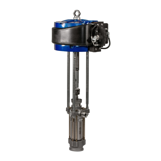
XL
10000 Air Motor
For use with high output reciprocating Graco pumps. For professional use only.
Important Safety Instructions
Read all warnings and instructions in this manual and in related
manuals. Save all instructions.
Model No. 24X856
100 psi (0.7 MPa, 7 bar) Maximum Working Pressure
Model No. 273088
100 psi (0.7 MPa, 7 bar) Maximum Working Pressure
(For use on XP-hf systems only)
334644C
EN
Advertisement
Table of Contents

Related Manuals for Graco XL 10000


Summary of Contents for Graco XL 10000
- Page 1 Instructions - Parts ™ 10000 Air Motor 334644C For use with high output reciprocating Graco pumps. For professional use only. Important Safety Instructions Read all warnings and instructions in this manual and in related manuals. Save all instructions. Model No. 24X856 100 psi (0.7 MPa, 7 bar) Maximum Working Pressure...
-
Page 2: Table Of Contents
Air Regulator ......8 Graco Information ......26 Air Filter . -
Page 3: Warnings
Warnings Warnings The following warnings are for the setup, use, grounding, maintenance, and repair of this equipment. The exclama- tion point symbol alerts you to a general warning and the hazard symbols refer to procedure-speci• c risks. When these symbols appear in the body of this manual or on warning labels, refer back to these Warnings. Product-speci• c hazard symbols and warnings not covered in this section may appear throughout the body of this manual where applicable. - Page 4 Warnings FIRE AND EXPLOSION HAZARD Flammable fumes, such as solvent and paint fumes, in work area can ignite or explode. Paint or solvent • owing through the equipment can cause static sparking. To help prevent • re and explosion: • Use equipment only in well ventilated area.
- Page 5 Warnings PERSONAL PROTECTIVE EQUIPMENT Wear appropriate protective equipment when in the work area to help prevent serious injury, including eye injury, hearing loss, inhalation of toxic fumes, and burns. Protective equipment includes but is not limited to: • Protective eyewear, and hearing protection. •...
-
Page 6: Component Identification
Component Identification Component Identification Key: Directional Air Valve Static ground cable Air inlet, 1 in npt (f) Plug for optional solenoid Muffler Optional reed switch mount Pilot valve External pilot lines Manifold De-ice bleed air valve Manual Shuttle Override Button Lift ring (800 lb, 363 kg) maximum Ground screw Pump drive rod... -
Page 7: General Information
General Information General Information The XL 10000 air motor is air piloted with two poppet • Move the valve off center due to ice or debris. valves operating a cup and plate main air shuttle valve. Air exhausts around the cylinder, through sound absorp- •... -
Page 8: Grounding
The minimum Motor Lubrication recommended air • ltration is 40 micron. Graco does not require lubrication beyond the grease Air Lubrication installed at the factory or through regular maintenance. With good quality compressed air and normal ambient 237212 1”... -
Page 9: Run Motor Manually
Grounding Run Motor Manually Use the manual override buttons (F) on each end of the air valve to physically move the internal main shuttle valve from one position to the other. Run the motor man- ually to: • Move the valve off center due to ice or debris. •... -
Page 10: Troubleshooting
Troubleshooting Troubleshooting Problem Cause Solution Air motor will not run and there is no Check air supply Supply air to motor inlet. obvious exhaust Pump is locked up. Disconnect or remove pump to verify motor operation. Ice broke loose in manifold and Turn off and exhaust air. -
Page 11: Ice In Air Motor
Troubleshooting Problem Cause Solution Air motor pauses at top change over. Top pilot valve exhaust restricted by Swap pilot valve or clear exhaust dirt or ice. port. Air motor pauses at bottom change Bottom pilot valve exhaust restricted Swap pilot valve or clear exhaust over. -
Page 12: Repair
Repair Repair Preventive Maintenance 1. Engage trigger lock. Schedule 2. Close the bleed-type master air valve. The operating conditions of your system determine how 3. Disengage the trigger lock. often maintenance is required. Establish a preventative 4. Hold a metal part of the gun firmly to a grounded maintenance schedule by recording when and what kind metal pail. -
Page 13: Repair Air Valve
Repair Repair Air Valve Replace Seals or Rebuild Air Valve See Kits and Accessories, page 22, to order kits for your pump. Replace Complete Air Valve Disassemble the Air Valve 1. Perform steps 1–5 from Replace Complete Air Valve, page 13. 2. - Page 14 Repair Apply high quality lithium grease. . 5 Air Valve Assembly 334644C...
- Page 15 Repair Reassemble the Air Valve 1. Lubricate detent cam (104) and install into housing. 2. The piston (102) and u-cup seals (108) come pre-assembled. Lubricate the u-cup seals (108) on both ends of the piston (102) and install it in the housing.
-
Page 16: Replace Pilot Valves
Repair Replace Pilot Valves 3. Hold the • ats of the air motor piston rod with a wrench. Use another wrench to loosen the coupling nut (CN). Collect the coupling collars and set aside. 1. Stop the pump at the middle of its stroke. Relieve the pressure. - Page 17 Repair Disassemble the Air Motor 5. Remove the muffler (12) from around the cylinder. Remove the cylinder (3). 1. Disconnect pilot valve air lines (55) from the air valve (13). 6. Slide the piston assembly (4) straight up off the bot- tom cover (1).
- Page 18 Repair Reassemble the Air Motor 7. Install the muffler (12) around the cylinder (3) and in the groove on the bottom cover(1). Be sure the front NOTE: The bearing (7) is pressed in the bottom cover opening is lined up with the • at on the bottom cover (1) and is only available with Bottom End Cap Repair kit (1).
-
Page 19: Parts
Parts Parts Part No. 24X856 and 273088 Apply lithium grease. Torque to 60 +/- 2 ft-lbs. (81 +/- 2.7 N•m) Torque to 95-105 in-lb (11-12 N•m). Piston rod (6) must move through bearing (7) without force. Press to snap fit. Lips face up. - Page 20 Parts Part Description Part Description 1 24X559 COVER, bottom 19 24A915 KIT, bumper, top and bottom (with screws) 17R815 COVER, bottom, motor, XP-hf 108014 PACKING, o-ring (For model 273088) 24W584 COVER, top 22 GASKET, end cap 3 24X561 KIT, cylinder 110036 BOLT, M8 x 1.25 x 45 mm 4...
-
Page 21: Air Valve Parts
Parts Air Valve Parts Apply high quality lithium grease. See Kits and Accessories, page 22. Part Description HOUSING, valve, air, XL Part Description 102 PISTON, valve, air, XL 113 CUP, valve, air, xl, zinc 103 PISTON, detent, small 114 ROLLER, detent, small 104... -
Page 22: Kits And Accessories
Parts Kits and Accessories Table 1 XL Air Motor Repair Kits Air Motor Parts Part No. Description Ref. NXT103 Lift Ring (17) 24X557 Piston/Rod Air Motor Parts Assembly Repair Kit Part No. Description Ref. -- 15G478 Bumper (18) 24X559 Bottom End Cap Piston Repair Kit Shaft, Piston, Rod... - Page 23 Parts Table 2 XL Air Motor Repair Kits Air Motor Parts Air Motor Parts Part No. Description Ref. Part No. Description Ref. 24X562 Repair, Complete 24X567 Roller Assembly Valve Assembly Piston, Detent (103) Valve, Air, XL (13) Cam, Detent (104) 24X565 Kit, gasket, valve (2 (27)
-
Page 24: Dimensions (Model No. 24X856)
Dimensions (Model No. 24X856) Dimensions (Model No. 24X856) in. (mm) in. (mm) in. (mm) in. (mm) in. (mm) in. (mm) 14.25 (361.9) 16.66 (423.2) 21.75 (552.5) 17.9 (454.7) 2.63 (66.8) 7.38 (187.5) Mounting Hole Diagram 334644C... -
Page 25: Dimensions (Model No. 273088)
Dimensions (Model No. 273088) Dimensions (Model No. 273088) in. (mm) in. (mm) in. (mm) in. (mm) in. (mm) in. (mm) 14.25 (361.9) 17.03 (432.5) 21.75 (552.5) 17.9 (454.7) 2.65 (67.3) 7.8 (198.1) Mounting Hole Diagram 334644C... -
Page 26: Technical Specifications
Technical Specifications XL 10000 Air Motor Metric Maximum Air Inlet Pressure 100 psi 0.7 MPa, 7 bar Stroke Length (Nominal) 4.8 in. 122 mm Motor Effective Area 132.7 in. 856 cm Motor Cylinder Inside Diameter 13 in. 330 mm Minimum Filtiation Size 0.0016 in. -
Page 27: Graco Standard Warranty
With the exception of any special, extended, or limited warranty published by Graco, Graco will, for a period of twelve months from the date of sale, repair or replace any part of the equipment determined by Graco to be defective.