Advertisement
INSTRUCTIONS-PARTS LIST
This manual contains important
warnings and information.
READ AND KEEP FOR REFERENCE.
INSTRUCTIONS
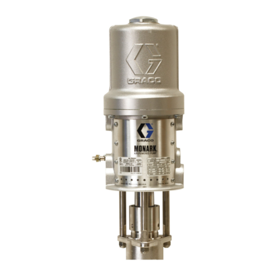
Monark Air Motors
180 psi (12 bar, 1.2 MPa) Maximum Air Working Pressure
Model 204–237, Series M
For in-line mounting
Model 206–955, Series G
For stanchion tube mounting
Model 205–997, Series G
Model 215–363, Series A
Model 945–972, Series A
Model 222–791, Series A
For 3 tie rod mounting
Model 207–546, Series F (Sanitary Pump)
For hinged clamp mounting
GRACO INC. P.O. BOX 1441 MINNEAPOLIS, MN 55440–1441
COPYRIGHT 1970, GRACO INC.
Graco Inc. is registered to I.S. EN ISO 9001
307–043
Rev. N
Supersedes M
05702
Advertisement
Table of Contents


Need help?
Do you have a question about the Monark M Series and is the answer not in the manual?
Questions and answers