EcoFlow Smart Home Panel Installation Manual
Hide thumbs
Also See for Smart Home Panel:
- User manual ,
- Installation manual (168 pages) ,
- Installation instruction (27 pages)
Table of Contents
Advertisement
Quick Links
Smart Home Panel
Installation Manual
The EcoFlow Smart Home Panel must be installed by a licensed electrician, who should
be familiar with all electrical codes, electrical wiring practices and experience working
with home electrical systems. Any accident, damage or personal injury caused by
incorrect installation is the sole responsibility of the user.
WARNING
Advertisement
Table of Contents

Related Manuals for EcoFlow Smart Home Panel


Summary of Contents for EcoFlow Smart Home Panel
- Page 1 Smart Home Panel Installation Manual The EcoFlow Smart Home Panel must be installed by a licensed electrician, who should be familiar with all electrical codes, electrical wiring practices and experience working with home electrical systems. Any accident, damage or personal injury caused by incorrect installation is the sole responsibility of the user.
-
Page 2: Table Of Contents
CONTENTS 1. Safety Instructions 2. Specifications 3. Product Details 3.1 External Features 3.2 Internal Features 4. What's in the box 5. Installation SOP Checklist 6. Installation Steps 6.1 Preparation 6.2 Installation 6.2.1 Installing the Relay Module 6.2.2 Mounting 6.2.3 Wiring 7. -
Page 3: Safety Instructions
SHP. Smart Home Panel by itself does not provide an AFCI (Arc Fault Circuit Interrupter) function. AFCI or GFCI protection may be available with an external AFCI accessory. Consult EcoFlow support for AFCI or GFCI solutions. -
Page 4: Specifications
18.5 lbs (8.38 kg) Dimensions 20 × 12.2 × 4.5 in (508 × 311 × 115 mm) Mounting Type Wall Mount Standard Connector EcoFlow Infinity Port Type of Enclosure Type 1 Warranty Description 5 Years Maximum # of Circuits Controlled... -
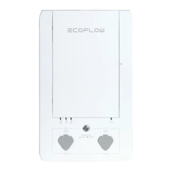
Page 5: Product Details
3. Product Details 3.1 External Features 1. Load Circuit Control Board The SHP can be set up to control a total of 10 load circuits, circuits 1, 3, 5, 7, 9 on the left and 2, 4, 6, 8, 10 on the right. -
Page 6: Internal Features
5. IOT Reset Button and Indicator This button can be used to turn on the Bluetooth hotspot for 5 minutes for the user to connect. 6. Error Indicator This indicator is normally off if no fault is present inside the SHP. It will turn red if there is a fault in the product. Users can go to the app for a fault diagnostic report. - Page 7 These are the wire connectors for hot wires coming from the circuit breakers in your main panel. 9. Switching Connector for Single/Split Phase Operation For split phase operation (North America and Japan ONLY), this connector should be removed permanently from the product. Split-phase also requires additional setup in the EcoFlow app.
-
Page 8: What's In The Box
4. What’s in the Box Smart Home Panel Infinity Cable and Wires A bag of accessories Product Installation Wall mounting brackets Product User Manual Manual Relay module NOTE The AWM wires can be removed from the harness plugs and replaced with an appropriate length and type of... -
Page 9: Installation Sop Checklist
Status Before installation- Project information Determine the installation location. The Smart Home Panel is rated to IP20, therefore, it needs to be installed away from direct sunlight, rain, snow and moisture. Determine the distance between the SHP and main electrical panel. - Page 10 App Store and create an EcoFlow account. Open the app on your mobile device, log into the app and add the Smart Home Panel to your device pool. For first time users, the app will lead through a commissioning process to setup the SHP.
- Page 11 Checklist Status Connect the DELTA Pro and Smart Home Panel using the Infinity cable. For split- phase, two DELTA Pros and two infinity cables are required. Turn on the main power button of DELTA Pro, then press the On/Off button (AC button, near the infinity port) on the SHP to enable each DELTA Pro.
-
Page 12: Installation Steps
6. Installation Steps 6.1 Preparation Tools and Items Needed for Installation: Tools required: Level Phillips head screwdriver, Torx T20 screwdriver and 7mm socket screwdriver Pliers Wire cutters Wire nuts Drill Conduit (e.g. 1,1/4 inch and 1 inch), Conduit whip Wire harness Tape measure Multimeter Voltage detector... - Page 13 Total Running Load 6900 W Largest Estimated Simultaneous Running Load (LESRL) 2300 W Largest Startup Wattage (LSW) 2000 W Minimum Backup Power Needed = LESRL + LSW 4300 W (Two DELTA Pros) NOTE Inductive loads such as air conditioners, clothes dryers or pumps have high Inrush current when starting. This may trip the relay modules because of overload.
-
Page 14: Installation
6.2 Installation De-energize the system: When you are ready to start the installation work, turn off the main breaker as well as each branch circuit breaker intended to be connected. Ensure that DELTA Pros are not connected to the SHP as well. - Page 15 Relay Module Position DELTA Pro DELTA Pro Install Relay Module 1. (a) Open the panel cover using the T20 screwdriver. (b) Slide out the screw cover on top. (c) Release the four screws one by one.
-
Page 16: Mounting
2. (a) Plug in each relay module and seat firmly (it is recommended to use the palm of your hand). (b) Secure the relay module by tightening the two screws. (c) Close the front panel, and secure the four screws. (d) The Relay Module installation is complete. - Page 17 wall Attach the top mounting bracket along the top edge of the mark on the wall. Make sure you also check the length of the flexible conduit. Hang the SHP up on the wall bracket. Secure the bottom mounting bracket to the wall. wall...
-
Page 18: Wiring
6.2.3 Wiring Wiring inside the Smart Home Panel All wires come labeled in the box, 12 input wires, labeled "1 in - 10 in" "Pro1 in, Pro2 in" connected to the circuit breakers, 10 output wires, labeled "1 out - 10 out" connecting to the load hot wires, two neutral wires connecting to the neutral bus bar in the main panel and ground wire connecting to the ground bus bar in the main panel. - Page 19 Wiring in the Electrical Panel Turn off the main breaker as well as the 10 branch circuit breakers intended to be connected in the main panel and use a voltage detector or voltmeter to make sure the system is fully de-energized. Remove the front cover of the main panel.
- Page 20 Main 11/4in Conduit Two Ne w Beakers added fo r Delt a Pr o Charging 2. Connect input wires from SHP to corresponding breakers of the main electrical panel and output wires to the load port of the main electrical panel. Main 1 in conduit 1 1/4 in conduit...
- Page 21 2. Follow steps below to wire up the product: 2.1. Connect the grounding wire from the ground bus of the main electrical panel to the EcoFlow AFCI/GFCI Box. 2.2. Connect input wires from SHP to corresponding breakers of the main electrical panel.
- Page 22 1, 3, 5, 7, 9 of SHP; L2 phase to 2, 4, 6, 8, 10 of SHP). L1 phase wiring Main 1 in Conduit 11/4in Conduit Two Ne w Beaker s added fo r Delt a Pr o Charging Smart Home Panel Main Electrical Panel...
- Page 23 Delt a Pr o Charging Smart Home Panel Main Electrical Panel Split-phase with GFCI or AFCI breakers 1. Connect the grounding wire from the ground bus of main electrical panel to the grounding terminal of EcoFlow AFCI/GFCI Box. Main Main electrical panel...
- Page 24 2. Connect L1 phase and L2 phase of the main electrical panel to corresponding inputs of SHP. Output wires of SHP are connected to corresponding hot wire terminals. 1 in conduit Metallic conduit Main 1 1/4 in conduit Metallic conduit Two Ne w Beaker s adde d fo r Delt a Pr o Charging L1 phase wiring...
-
Page 25: System Commissioning And App Setup
EcoFlow App. Launch the EcoFlow App and add the device by tapping “+” icon on the top right. Find the SHP and tap it to pair. After Bluetooth connection, you will be asked to choose the Wi-Fi and enter Wi-Fi password to finish network configuration. -
Page 26: Faq
By using EcoFlow Products, Applications, and Services, you consent to the EcoFlow Terms of Use and Privacy Policy, which you can access via the "About" section of the "User" page on the EcoFlow App or the official EcoFlow website at https://ecoflow.com/pages/terms-of-use and https://ecoflow.com/ pages/privacy-policy.
Need help?
Do you have a question about the Smart Home Panel and is the answer not in the manual?
Questions and answers