Table of Contents
Advertisement
Quick Links
Advertisement
Table of Contents

Summary of Contents for EndurEnergy Systems ESP-BCU HL
- Page 1 ESP-BCU HL User Manual Rev. 1 – Aug 16th, 2023...
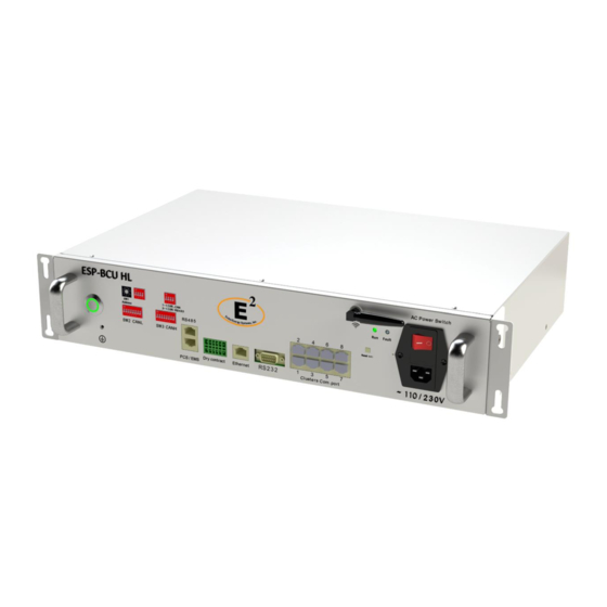
- Page 2 About this manual This manual is meant for the Battery Control Unit: ESP-BCU HL. This product is designed to enhance the capacity of energy storage systems. It is suitable for residential, commercial, and small industrial applications. The ESP-BCU HL supports multiple communication methods, including CAN, RS485, RS232, and Internet communication protocols.
-
Page 3: Table Of Contents
CONTENT Safety Introduction ............................2 Important Safety Instructions ....................... 2 Warnings in this Document ......................2 Battery Control Unit Handing Guide .................... 3 Response to Emergency Situations .................... 3 1.4.1 Leaking Batteries ........................3 1.4.2 Fire .............................. 4 1.4.3 Wet Unit ............................5 1.4.4 Damaged Battery Control Unit ................... -
Page 4: Safety Introduction
Safety Introduction Important Safety Instructions This manual contains crucial instructions for the ESP-BCU HL product. It is imperative to follow this manual during installation and use of the product. While this product is designed and tested to meet international safety requirements such as IEC 62040, and IEC 62619, it is essential to take certain precautions when installing and/or operating any electrical and electronic equipment. -
Page 5: Battery Control Unit Handing Guide
1.4.1 Leaking Batteries The ESP-BCU HL includes an auxiliary battery to maintain operation in the absence of an alternate power source. In case of electrolyte leakage from the auxiliary battery, it's imperative to prevent any contact with the leaked liquid or gas. Electrolyte possesses corrosive properties and can result in skin irritation and chemical burns. -
Page 6: Fire
• Eye contact: Rinse your eyes with flowing water for at least 15 minutes. Seek medical attention promptly. • Skin contact: Wash the affected area thoroughly with soap and water. Seek medical attention as soon as possible. • Ingestion: If the electrolyte is ingested, promptly induce vomiting. Seek immediate medical attention. -
Page 7: Wet Unit
Installers It is highly recommended that the installation of the ESP-BCU HL is carried out by a skilled worker or electrician. A skilled worker is defined as an individual who has received proper... -
Page 8: Disposing
If the package is deemed to be non-shippable, the contents shall be promptly collected, segregated, and either the consignor or consignee should be contacted. ⚫ The AC circuit of the ESP-BCU HL has been disconnected and turned off prior to shipping. -
Page 9: Product Introduction
3 Product Introduction Technical Specifications Product Model ESP-BCU HL Port Power 40 W Power Supply 13-17 VDC / Backup battery Nominal Discharge/Charge 15 W Power UPS Rated Capacity 15 Ah UPS Nominal Current UPS Power Supply 12 V Communication Protocols... -
Page 10: Indicators And Ports
Indicators and Ports 3.2.1 Indicators There are two LED indicators on the front of the battery control unit that show its operating status. Item Designation Definition Steady: The battery control unit is working normally. Blinking: Reset Button pressed, expecting Wi-Fi connection from App. - Page 11 SW 1 1 and 2 This is a combination of two DIP switches: one rotary DIP switch and one slide DIP switch. Both switches are used according to the number of batteries, and the battery clusters. CAN/RS485 The DIP switch is used to select the communication mode Switch used between the BCU and the inverter, you can set it to CAN or RS485.
-
Page 12: System Layout
Conversely, when the AC Power Switch is in the "Off" position, it interrupts the flow of AC electricity to the battery control unit. AC Power Power cable connection designed to deliver alternating Socket current (AC) electrical power to the battery control unit. Connect this input to an AC outlet to provide energy to the BCU. -
Page 13: Feature
Feature This product is designed to enhance the capacity of energy storage systems. It is suitable for residential, commercial, and small industrial applications. The ESP-BCU HL has the following features: • Support for Multi-Cluster Batteries: This unit enables seamless connectivity for multi-cluster batteries, both in series and parallel configurations. -
Page 14: Installation Location
Installation Location Ensure that the installation location meets the following conditions: ⚫ The building is designed to withstand earthquakes as per the building code (when applicable). ⚫ It is far away from the sea to avoid saltwater and humidity. ⚫ The floor is flat and level. ⚫... -
Page 15: Personal Protective Equipment (Ppe)
Personal protective equipment (PPE) When handling the battery control unit, the following safety gear should be worn. Installers must comply with the relevant requirements of UL1973, IEC 62040, and IEC 62619, or applicable domestic legislation and other relevant international standards. Insulated gloves Safety goggles Dielectric Safety shoes... -
Page 16: Battery Installation
EndurEnergy does not provide cables for all situations, for special projects ask sales team. Mounting The ESP-BCU HL is designed as a rack mount type battery control unit, this adds flexibility on installation and modularity for different configurations. 5.2.1 Rack Mounting (R6 / R12) 1. - Page 17 2. Adjust leveler feet (if included), lower each leveler unit it reaches the floor, make sure each leveler contacts the floor solidly. After lowering each leveler, use the carpenter's level / bubble level to confirm that the rack is level. Adjust levelers as needed to get level.
- Page 18 4. Slide the battery control unit into the horizontal brackets of the rack. Ensure that each battery control unit or batteries are vertically spaced out by 1/3 U (0.583” / 14.82 mm) to facilitate heat dissipation. Utilize M6 screws to securely fasten the batteries in place onto cage nuts, with a maximum torque of 8.7 lb*ft.
-
Page 19: Enclosure Mounting - (Bu10/15/20/30)
5.2.2 Enclosure Mounting - (BU10/15/20/30) 1. Place the enclosure in the location desired (refer to the details about the installation location described in Chapter 4.2). The enclosure should be moved close to its installation location inside its shipping container before it is unpacked. The enclosure must be installed in a structurally sound area with a level floor that is able to bear the weight of the enclosure + the weight of the battery control unit + the intended number of batteries to be installed inside. - Page 20 2. In order to secure the enclosure to the building structure for stability, adjust the 2x wall brackets by losing the screws, move the brackets to leave a gap of at least 0.5” between the wall and the enclosure to allow airflow and door opening. Tighten the screw brackets and attach both brackets to the wall with 2x adequate screws (M8 or 5/16”).
- Page 21 3. Fix the enclosure to the floor by using 4x adequate screws (M8 or 5/16”). Verify foundation for seismic installations.
-
Page 22: Cable Connections Of The Battery
Cable Connections of the Battery WARNING Although the ESP-BCU HL does not have any direct power connection with the high- voltage batteries, it will be installed beside them. Therefore, we encourage you to connect the cables in accordance with local installation laws and regulations. Before connecting the cables, ensure that the battery is turned OFF. -
Page 23: Battery Control Unit Grounding
5.3.1 Battery Control Unit Grounding There is a grounding icon on the front of the battery that indicates the grounding screw of the battery, connect the grounding wire on this screw and make sure all the batteries grounds are interconnected, this ground shall also be connected to the bonding ground of the inverter or PCS where the batteries will be installed, the ground bonding system shall be installed as per NEC Article 250 or local regulations. - Page 24 However, the network cable connecting the battery and the ESP-BCU HL should conform to the specifications outlined by the Inverter. If available, a LAN cable tester can be employed to determine whether the cable is faulty.
- Page 25 5.3.2.2 Connecting battery string for communication with battery control unit NOTICE The battery is designed to work on a close loop environment for communicating with the inverter / PCS (check inverter compatibility list), for open loop type of applications we do not ensure proper operation.
- Page 26 5.3.2.3 Connecting battery control unit for communication with inverter NOTICE The battery control unit is designed to work on a close loop environment for communicating with the inverter / PCS (check inverter compatibility list), for open loop type of applications we do not ensure proper operation.
- Page 27 5.3.2.3.1 Communication connection example: 4 strings of 4*ESP-5K-HL to a SA-60K inverter WARNING Always follow Inverter’s installation manual prior to making any connection. This manual does not substitute inverter manual. NOTICE Once you complete the wiring for communication, verify the inverter manual or with inverter technical support for the correct settings on the inverter to properly ensure communication.
-
Page 28: Battery Control Unit Dip Switch Setting
Battery Control Unit DIP Switch Setting The settings for the DIP switches are defined in the inverter's user manual. WARNING: Please ensure that the SW2/SW3/Protocol Switch settings are correctly set to the manufacturer's default and have not been accidentally changed. The default communication protocol for the battery is CAN (Protocol Switch 1 &... - Page 29 SW1 Slide DIP Switch Number of Battery Clusters Connected Clusters connected in Parallel Clusters connected in Series** - Standard WARNING: ** Typical application is to connect the clusters in parallel, for series clustering the voltage limit is 1000 VCD (18 batteries), never exceed this or the system could be damaged. Consult EndurEnergy if in doubt.
-
Page 30: Commissioning
The rotary DIP switch on the ESP-BCU HL Battery Control Unit allows you to set the number of batteries in a group. Each position on the switch corresponds to a specific number of batteries, ranging from 1 battery to 16 batteries. The DIP switch has 16 positions labeled 0, 1, 2, 3, 4, 5, 6, 7, 8, 9, A, B, C, D, E, and F. -
Page 31: Shutting Down
Step 4: Powering On • Plug the 220V power cable into the AC power socket. (The ESP-BCU HL is equipped with a built-in UPS battery that can provide continuous power for up to 3 hour if no power is available nearby.) •... - Page 32 If there is a persistent fault indicator in the battery control unit, review the connections and dip switch settings again as well as the inverter connections and settings. If the problem persists and you require further assistance, please contact us (see Section 1.7).
Need help?
Do you have a question about the ESP-BCU HL and is the answer not in the manual?
Questions and answers