
Related Manuals for Neousys Technology NRU-230V-AWP Series


Summary of Contents for Neousys Technology NRU-230V-AWP Series
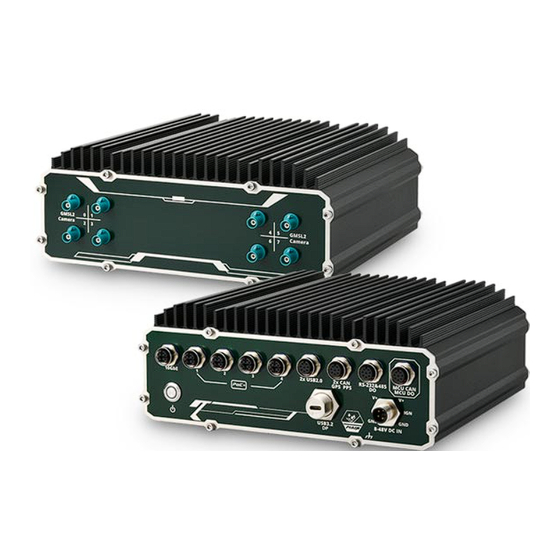
- Page 1 Neousys Technology Inc. NRU-230V-AWP Series NRU-240S-AWP Series User Manual Revision 1.0...
-
Page 2: Table Of Contents
Table of Content Table of Contents Table of Contents ........................2 Legal Information ........................4 Contact Information ....................... 5 Declaration of Conformity ..................... 5 Copyright Notice ........................6 Safety Precautions ......................... 7 Battery Warning........................7 Service and Maintenance ...................... 8 ESD Precautions ........................ - Page 3 Table of Content Ignition Power Control Principles of Ignition Power Control............... 62 4.1.1 Additional Features of Ignition Power Control ........... 63 4.1.2 Wiring Ignition Signal ..................64 4.1.3 Operation Modes of Ignition Power Control ............65 Reflashing the NRU System...
-
Page 4: Legal Information
Legal Information Legal Information All Neousys Technology Inc. products shall be subject to the latest Standard Warranty Policy Neousys Technology Inc. may modify, update or upgrade the software, firmware or any accompanying user documentation without any prior notice. Neousys Technology Inc. will provide access to these new software, firmware or documentation releases from download sections of our website or through our service partners. -
Page 5: Contact Information
3384 Commercial Avenue, Northbrook, IL 60062, USA (Illinois, USA) Tel: +1-847-656-3298 Email, Website China Neousys Technology China Co., Ltd. Room 612, Building 32, Guiping Road 680, Shanghai Tel: +86-2161155366 Email, Website Declaration of Conformity This equipment has been tested and found to comply with the limits for a Class A digital device, pursuant to part 15 of the FCC Rules. -
Page 6: Copyright Notice
Neousys, the Neousys logo, Expansion Cassette, MezIO Patents and registered patents and trademarks of Neousys Technology, Inc. Trademarks Windows is a registered trademark of Microsoft Corporation. AMD, Ryzen™ are registered trademarks of Advanced Micro Devices, Inc All other names, brands, products or services are trademarks or registered trademarks of their respective owners. -
Page 7: Safety Precautions
This product is intended to be supplied by a Listed Power Adapter or DC power source, rated up to 5000m altitude operation. If further assistance is required, please contact Neousys Technology ⚫ If the system is not going to be used for a long time, disconnect it from mains... -
Page 8: Service And Maintenance
Service and Maintenance/ ESD Precautions Service and Maintenance ⚫ ONLY qualified personnel should service the system ⚫ Shutdown the system, disconnect the power cord and all other connections before servicing the system ⚫ When replacing/ installing additional components (expansion card, memory module, etc.), insert them as gently as possible while assuring proper connector engagement ESD Precautions... -
Page 9: About This Manual
NRU-230V-AWP/ NRU-240S-AWP Series About This Manual This manual introduces and demonstrates installation procedures of Neousys NRU-230V-AWP/ NRU-240S-AWP systems featuring NVIDIA® Jetson AGX Orin™ platform. The manual also demonstrates the system’s general installation procedures. Revision History Version Date Description Jun. 2024 Initial release... -
Page 10: Introduction
NRU-230V-AWP/ NRU-240S-AWP Series Introduction NRU-230V-AWP/ NRU-240S-AWP are rugged, IP66 waterproof NVIDIA® Jetson AGX Orin computers targeting edge AI applications for harsh environments, ranging from roadside, food & chemical factories, mining, construction, agriculture, or harbor. It aims to redefine rugged Edge AI with waterproof features at an affordable cost through its streamlined mechanical design, standardized cable kit, and carefully selected waterproof connectors. -
Page 11: Nru-230V-Awp Specifications
NRU-230V-AWP/ NRU-240S-AWP Series NRU-230V-AWP Specifications System Core ™ ® ® Processor NVIDIA Jetson AGX Orin System-on-Module (SOM), comprising NVIDIA Ampere GPU and Arm Cortex-A78AE CPU Memory 32GB/ 64GB LPDDR5 (JAO 32GB/ JAO64GB) @ 3200 MHz on SOM eMMC 64GB eMMC 5.1 on SOM Panel I/O Interface 8x GMSL2 FAKRA Z connectors Configuration A. - Page 12 NRU-230V-AWP/ NRU-240S-AWP Series M.2 NVMe 1x M.2 2280 M key socket (PCIe Gen4x2) for NVMe SSD Power Supply DC Input 8V to 48V DC input and ignition power control via M12 L-coded, 5-pin connector* Mechanical Dimension 225 mm (W) x 195 mm (D) x 89 mm (H) Weight 4.4kg (excluding wall-mount bracket) Mounting...
-
Page 13: Nru-240S-Awp Specifications
NRU-230V-AWP/ NRU-240S-AWP Series NRU-240S-AWP Specifications System Core ™ ® ® Processor NVIDIA Jetson AGX Orin System-on-Module (SOM), comprising NVIDIA Ampere GPU and Arm Cortex-A78AE CPU Memory 32GB/ 64GB LPDDR5 (JAO 32GB/ JAO64GB) @ 3200 MHz on SOM eMMC 64GB eMMC 5.1 on SOM Panel I/O Interface Ports 1 to 4: Gigabit Ethernet ports by Intel®... - Page 14 NRU-230V-AWP/ NRU-240S-AWP Series Mechanical Dimension 225 mm (W) x 195 mm (D) x 89 mm (H) Weight 4.4kg (excluding wall-mount bracket) Mounting Wall-mount bracket (standard) Environmental Operating -25°C to 70°C (30W TDP mode, without 10GbE transmission and PoE Load) ** Temperature -25°C to 60°C (30W TDP mode, with full function) With full CPU+GPU stressing:...
-
Page 15: Dimension Of Nru-230V-Awp/ Nru-240S-Awp
NRU-230V-AWP/ NRU-240S-AWP Series Dimension of NRU-230V-AWP/ NRU-240S-AWP NOTE All measurements are in millimeters (mm). NRU-230V-AWP and NRU-240S-AWP share the same dimensions, therefore NRU-230V-AWP will be used for demonstration purposes. 1.3.1 Front Panel View 1.3.2 Side Panel View... -
Page 16: Rear Panel View
NRU-230V-AWP/ NRU-240S-AWP Series 1.3.3 Rear Panel View 1.3.4 Bottom View... -
Page 17: System Overview
Upon receiving and unpacking your system, please check immediately if the package contains all the items listed in the following table. If any item(s) are missing or damaged, please contact your local dealer or Neousys Technology. NRU-230V-AWP Packing List Item... -
Page 18: Nru-230V-Awp/ Nru-240S-Awp Series Front Panel
NRU-230V-AWP/ NRU-240S-AWP Series NRU-230V-AWP/ NRU-240S-AWP Series Front Panel NOTE NRU-230V-AWP and NRU-240S-AWP share the same front panel I/Os. The front panel of the system features M12 ports such as 10GbE, IEEE 802.3at PoE+, USB2.0, CAN GPS PPS, COM, isolated CAN/ DO by automotive-grade MCU, wide range 8V to 48V, ignition power control. - Page 19 NRU-230V-AWP/ NRU-240S-AWP Series M12 L-coded DC input with ignition 8V to 48V DC input and ignition power control power control M12 A-coded Automotive-grade MCU with isolated CAN2.0 and isolated DO MCU CAN/ DO...
-
Page 20: M12 X-Coded 10Gb Ethernet
NRU-230V-AWP/ NRU-240S-AWP Series 2.3.1 M12 X-coded 10Gb Ethernet The system offers one 10Gb Ethernet port, implemented via M12 X-coded connector using Marvell® AQC113 controller on the front panel. The port is backwards compatible with 5Gb, 2.5Gb, and Gb Ethernet connections. Connector Pin Definition Panel side Cable connector end... -
Page 21: Power Button
NRU-230V-AWP/ NRU-240S-AWP Series 2.3.2 Power Button The power button is a non-latched switch for ATX mode on/off operation. Press to turn on the system, and to turn off, you can either issue a shutdown command in the OS, or just press the power button. -
Page 22: Ieee802.3At Power Over Ethernet
NRU-230V-AWP/ NRU-240S-AWP Series 2.3.3 IEEE802.3at Power Over Ethernet The system offers GbE with PoE+ via M12 X-coded connectors on the front panel. Power over Ethernet (PoE) supplies electrical power and data on a CAT-5/CAT-6 Ethernet cable. Acting as a PoE PSE (Power Sourcing Equipment), compliant with IEEE 802.3at, each PoE port delivers up to 25.5W to a Powered Device (PD). -
Page 23: Usb2.0 Port
NRU-230V-AWP/ NRU-240S-AWP Series 2.3.4 USB2.0 Port The USB2.0 ports are backward compatible with USB 1.1 and USB 1.0 devices. Connector Pin Definition Panel side Cable connector end Signal M12 panel side M12 cable connector end Wire color USB0_DATA+ USB0_DATA- USB0_VCC USB0_GND USB1_GND USB1_VCC... -
Page 24: Type-C Usb3.2 Gen 1 Or Alternative Displayport
NRU-230V-AWP/ NRU-240S-AWP Series 2.3.5 Type-C USB3.2 Gen 1 or Alternative DisplayPort The system’s USB 3.2 Gen1x1 type-C port offers up to 5Gbps of data transfer bandwidth. The port is backward compatible with USB3.2 Gen.1 USB 2.0, USB 1.1 and USB 1.0 devices via a USB hub (not included) to connect to external devices. -
Page 25: Isolated Can 2.0 & Isolated Digital Input (Gps Pps)
NRU-230V-AWP/ NRU-240S-AWP Series 2.3.6 Isolated CAN 2.0 & Isolated Digital Input (GPS PPS) The connector has two isolated CAN buses and a GPS PPS input signal. The CAN bus is a robust industrial bus with a pair of differential signals and is commonly used in various industrial and in-vehicle applications. -
Page 26: Rs-232, 485 And Do
NRU-230V-AWP/ NRU-240S-AWP Series 2.3.7 RS-232, 485 and DO Connector Pin Definition M12 panel side Signal M12 cable connector end RS485_DATA- P3_Pin 3 RS485_DATA+ P3_Pin 2 RS485_GND P3_pin 5 DO_H Open Wire_Red DO-L Open Wire_Black RS232_GND P4_Pin 5 RS232_RX P4_Pin 2 RS232_TX P4_Pin 3... -
Page 27: Mcu Can/ Mcu Do
NRU-230V-AWP/ NRU-240S-AWP Series 2.3.8 MCU CAN/ MCU DO M12 panel side Signal M12 cable connector end MCU_CAN_H P3_Pin 3 MCU_CAN_GND P3_Pin 2 MCU_CAN_L P3_pin 5 MCU_DO_H Open Wire_Red MCU_DO_L Open Wire_Black... - Page 28 NRU-230V-AWP/ NRU-240S-AWP Series Wiring for DIO The digital input function is implemented using a photo-coupler with an internally series-connected 1kΩ resistor. You need to provide a voltage to specify the logic high/low state. The input voltage for logic high is 5~24V, and the input voltage for logic low is 0~1.5V. The digital output function is implemented using Power MOSFET + Analog Device iCoupler®...
-
Page 29: Dc-In Connector
NRU-230V-AWP/ NRU-240S-AWP Series 2.3.9 DC-in Connector The system accepts a wide range of DC power input from 8V to 48V with reverse polarity protection via a M12 L-coded connector. The M12 L-coded connectors offer COTS availability and ultra-rugged connection reliability when wiring DC power. WARNING Please make sure the voltage of DC power is correct before you connect it to the system. -
Page 30: Fakra Z Connector For Gmsl2 Camera (Nru-230V-Awp Only)
NRU-230V-AWP/ NRU-240S-AWP Series 2.3.10 FAKRA Z Connector for GMSL2 Camera (NRU-230V-AWP Only) Fachkreis Automobil (FAKRA) connector is a German standard for SubMiniature version B based automotive-grade connectors. There are eight FAKRA Z connectors on the rear panel side to connect to automotive GMSL2 cameras. Due to their advanced features such as IP67 waterproof, high dynamic range (120dB HDR), auto white balance (AWB), and LED flicker mitigation (LFM), automotive GMSL2 cameras are ideal for autonomous vehicle applications. -
Page 31: Internal I/O
NRU-230V-AWP/ NRU-240S-AWP Series Internal I/O The system’s internal I/O connectors consist of an M.2 B key slot for 5G/4G wireless communication module, two mini PCIe slots for wireless or storage modules, one M.2 M key for NVMe installation, and two 2.5" SATA SSD storage. 2.4.1 M.2 B Key 3042/ 3052 &... - Page 32 NRU-230V-AWP/ NRU-240S-AWP Series M.2 (B Key) Slot Pin Definition Pin # Signal Pin # Signal +3V3 +3V3 USB_D+ USB_D- Mechanical Key USB3.0-RX- USB3.0-RX+ UIM1-RESET UIM1-CLK USB3.0-TX- UIM1-DATA USB3.0-TX+ UIM1-PWR UIM2-DATA UIM2-CLK UIM2-RST UIM2-PWR PERST_N RESET_N +3V3 +3V3 +3V3...
-
Page 33: 2280 (M Key) For Nvme Ssd
NRU-230V-AWP/ NRU-240S-AWP Series 2.4.2 M.2 2280 (M Key) for NVMe SSD The system has a Gen4 x2 PCIe M.2 2280 slot for you to install an NVMe SSD. The M.2 NVMe SSD offers significantly better system performances when compared to a 2.5” SSD. - Page 34 NRU-230V-AWP/ NRU-240S-AWP Series M.2 (M Key) Slot Pin Definition Pin # Signal Pin # Signal +3V3 +3V3 PERN3 PERP3 PETN3 +3V3 PETP3 +3V3 +3V3 PERN2 +3V3 PERP2 PETN2 PETP2 PERN1 PERP1 PETN1 PETP1 PERn0 PERp0 PETn0 PETp0 PERST_N CLKREQ REFCLKN REFCLKP Mechanical Key +3V3...
-
Page 35: Mini-Pcie Slot (Pcie And Usb2.0 Signal)
NRU-230V-AWP/ NRU-240S-AWP Series 2.4.3 mini-PCIe Slot (PCIe and USB2.0 Signal) The mini-PCIe socket (in blue) accepts off-the-shelf mini-PCIe modules. You can add additional features to your system such as WiFi, GPS, etc. NOTE If the module is installed after the initial purchase, you may need to contact Neousys Technology or an authorized distributor for a customized panel with the required number of waterproof SMA antenna holes. - Page 36 NRU-230V-AWP/ NRU-240S-AWP Series mini-PCIe Pin Definition Pin # Signal Pin # Signal +3.3V +1.5V UIM_PWR UIM_DATA REFCLK- UIM_CLK REFCLK+ UIM_RST UIM_SPU Mechanical Key PERST# PERn0 +3.3V PERp0 +1.5V PETn0 PETp0 USB_D- USB_D+ +3.3V +3.3V +1.5V +3.3V WARNING Some off-the-shelf mini-PCIe 4G modules are not compliant to standard mini-PCIe interface.
-
Page 37: Mini-Pcie Slot And Sim (Usb 2.0 Signal Only)
NRU-230V-AWP/ NRU-240S-AWP Series 2.4.4 mini-PCIe Slot and SIM (USB 2.0 Signal Only) There is a full-size USB2.0 signal only mini-PCIe socket (indicated in blue) for better compatibility with off-the-shelf mini-PCIe wireless modules. For customers who want to install a mini-PCIe wireless module, please take advantage of the mini-PCIe socket, SIM card slot (indicated in red) and the antenna openings on the panels. - Page 38 NRU-230V-AWP/ NRU-240S-AWP Series mini-PCIe Pin Definition Pin # Signal Pin # Signal +3.3V +1.5V CLKREQ# Mechanical Key PERST# +3.3V +1.5V USB_D- USB_D+ +3.3V +3.3V +1.5V +3.3V...
-
Page 39: Dip Switch For Com/ Can Bus Port Configuration
NRU-230V-AWP/ NRU-240S-AWP Series 2.4.5 DIP Switch for COM/ CAN bus Port Configuration The system’s COM/ CAN bus ports are implemented via the NVIDIA Jetson module and can provide up to 115200 bps baud rate. The ports can be configured by adjusting the DIP switch. The following table describes the pin configuration and their definitions. -
Page 40: Sata Ports
NRU-230V-AWP/ NRU-240S-AWP Series 2.4.6 SATA Ports The system has two SATA ports which support SATA signals. Each SATA port (indicated in blue) features a SATA and power connector (indicated in red). Standard SATA/ power connectors are provided with the system. -
Page 41: System Installation
NRU-230V-AWP/ NRU-240S-AWP Series System Installation Before disassembling the system enclosure and installing components and modules, please make sure you have done the following: ⚫ It is recommended that only qualified service personnel should install and service this product to avoid injury or damage to the system. ⚫... -
Page 42: Disassembling The System Enclosure
NRU-230V-AWP/ NRU-240S-AWP Series Disassembling the System Enclosure To install internal components such as M.2 SSD or mini-PCIe module, you need to disassemble the system enclosure. Please refer to the following procedure: Turn the system upside-down and remove the screws indicated blue (with rubber stand). - Page 43 NRU-230V-AWP/ NRU-240S-AWP Series Gently lift the bottom panel open to access the internal expansion slots Remove the screws securing the heatsink on the motherboard.
- Page 44 NRU-230V-AWP/ NRU-240S-AWP Series Remove the screws indicated on the I/O panel. Gently slide the motherboard out of the enclosure.
- Page 45 NRU-230V-AWP/ NRU-240S-AWP Series Turn the motherboard upside-down to access the NVIDIA® Jetson AGX Orin™ SoM’s 699-pin interface connector.
-
Page 46: Installing Internal Components
NRU-230V-AWP/ NRU-240S-AWP Series Installing Internal Components 3.2.1 NVIDIA® Jetson AGX Orin™ SoM Installation The system has a dedicated 699-pin interface for NVIDIA® Jetson AGX Orin™, please refer to the following instructions for installation. 1. Please refer to the section Disassemble the system enclosure. - Page 47 NRU-230V-AWP/ NRU-240S-AWP Series 2. Simply match the SoM’s pin connector end to the motherboard, lower and push firmly into the motherboard until you hear a “click” sound. 3. If you need separate the SoM from the motherboard, place fingers on the SoM’s non-connector end, gently lift to un-clip the SoM off from the interface (indicated by the white dotted lines).
-
Page 48: B Key 3042/ 3052 & Sim Card Installation
NRU-230V-AWP/ NRU-240S-AWP Series 3.2.2 M.2 B Key 3042/ 3052 & SIM Card Installation The system has an M.2 2242/ 3042/ 3052 slot (indicated in blue rectangle) with dual SIM slots (indicated in rectangle) supporting 5G/ 4G. A copper standoff is provided for you to secure onto the motherboard into the red arrow location for an M.2 2242/ 3042 module, or into the... - Page 49 NRU-230V-AWP/ NRU-240S-AWP Series 4. Flip the holder back onto the SIM card and push in the direction shown to lock-in the SIM card into the slot. 5. Insert the M.2 B key module on a 45 degree angle and secure with a screw. To open the SIM slot, slide the micro SIM cover in the direction shown and flip open the slot.
-
Page 50: 2280 M Key Nvme Ssd Installation
NRU-230V-AWP/ NRU-240S-AWP Series 3.2.3 M.2 2280 M Key NVMe SSD Installation The system has a Gen4 x2 PCIe M.2 2280 slot for you to install an NVMe SSD. To install the NVMe SSD, please refer to the following procedure. 1. Please refer to the section Disassemble the system enclosure. - Page 51 NRU-230V-AWP/ NRU-240S-AWP Series 4. Remove the thermal pad’s protective film at the bottom of the enclosure panel for the NVMe module. Reinstall the enclosure when done. If you need to install other components, please refer to respective sections.
-
Page 52: Mini-Pcie Module Installation
NRU-230V-AWP/ NRU-240S-AWP Series 3.2.4 mini-PCIe Module Installation The system comes with two mini-PCIe sockets. The socket that only has USB2.0 signal also comes with a SIM card slot There are two mini-PCIe slots on the main board. Please follow the procedures for installation. 1. - Page 53 NRU-230V-AWP/ NRU-240S-AWP Series 3. Flip the holder back onto the SIM card and push in the direction shown to lock-in the SIM card into the slot. 4. To install, insert the gold finger end of the mini-PCIe card on a 45 degree angle into the slot, gently push the other end of the mini-PCIe onto the motherboard and secure it a screw.
-
Page 54: Installing 2.5" Hdd/ Ssd
NRU-230V-AWP/ NRU-240S-AWP Series 3.2.5 Installing 2.5” HDD/ SSD There are two HDD/SSD slots on the inside of enclosure’s bottom panel. Please follow the procedures for installation. 1. Remove bottom panel screws indicated. - Page 55 NRU-230V-AWP/ NRU-240S-AWP Series 2. Place a 2.5” HDD/ SSD into the drive mount and secure with four screws (indicated by arrows). Note the orientation of the drive’s connector with respect to the panel. 3. Connect the SATA cable to the connector.
- Page 56 NRU-230V-AWP/ NRU-240S-AWP Series 4. If you need to install the other HDD/ SSD, please repeat previous steps. 5. Place the panel back onto the enclosure, and secure the indicated screws (blue) at a torque range of 6.3 – 7.7kgf-cm in ascending order to complete the installation procedure.
-
Page 57: Installing The System Enclosure
NRU-230V-AWP/ NRU-240S-AWP Series Installing the System Enclosure Gently slide the motherboard back into the enclosure, make sure the goldfingers (indicated in red) are inserted properly into the slot (indicated in blue). Secure the hex bolt screws indicated on the I/O panel. - Page 58 NRU-230V-AWP/ NRU-240S-AWP Series Place the bottom panel back onto the system. Place the panel back onto the enclosure, and secure the indicated screws (blue) at a torque range of 6.3 – 7.7kgf-cm in ascending order to complete the installation procedure.
-
Page 59: Wall Mount Bracket Installation
NRU-230V-AWP/ NRU-240S-AWP Series Wall Mount Bracket Installation To install the wall mount bracket for the system, please refer to the following instructions. To install the damping bracket, please remove the four rubber stands at the bottom of the enclosure. - Page 60 NRU-230V-AWP/ NRU-240S-AWP Series Take out the wall mount bracket (in blue) and four M4 screws (in red) out of the accessory box and fix the wall mount bracket to the bottom of the system enclosure. Place the system on a flat surface portion of the wall and secure it with four (4) M4 screws. When wall mounting, place the heatsink fins perpendicular to the ground for better heat dissipation efficiency.
-
Page 61: Powering On The System
NRU-230V-AWP/ NRU-240S-AWP Series Powering On the System 3.5.1 Powering On Using the Power Button This is the simplest way to turn on your system. The power button on the side panel is a non-latched switch and behaves as the ATX-mode on/off control. With DC power connected, pushing the power button will turn on the system and the PWR LED indicator will light up. -
Page 62: Ignition Power Control
NRU-230V-AWP/ NRU-240S-AWP Series Ignition Power Control The ignition power control module for in-vehicle applications is an MCU-based implementation that monitors the ignition signal and reacts to turn on/off the system according to predefined on/off delay. Its built-in algorithm supports other features such as ultra-low power standby, battery-low protection, system hard-off, etc. -
Page 63: Additional Features Of Ignition Power Control
NRU-230V-AWP/ NRU-240S-AWP Series 4.1.1 Additional Features of Ignition Power Control In addition to the typical timing correlation, the ignition power control module offers additional features to provide additional reliability for in-vehicle applications. ⚫ Low battery detection The ignition power control module continuously monitors the voltage of DC input when the system is operational. -
Page 64: Wiring Ignition Signal
NRU-230V-AWP/ NRU-240S-AWP Series 4.1.2 Wiring Ignition Signal To have ignition power control for in-vehicle usage, you need to supply IGN signal to the system. The IGN input is located on the M12 L-coded 5-pin connector (shared with DC power input). For in-vehicle ignition control wiring, please do the following: 1. -
Page 65: Operation Modes Of Ignition Power Control
NRU-230V-AWP/ NRU-240S-AWP Series 4.1.3 Operation Modes of Ignition Power Control You can use the rotary switch to configure the operation mode. The system offers 16 (0~15) operation modes with different power-on/power-off delay configurations. Please refer to the “Disassembling the section system”... - Page 66 NRU-230V-AWP/ NRU-240S-AWP Series Mode Power-on Delay Power-off Delay Hard-off Timeout 10 seconds 10 seconds 10 minutes 10 seconds 1 minute 10 minutes 10 seconds 5 minutes 10 minutes 30 seconds 1 minute 10 minutes 30 seconds 5 minutes 10 minutes 30 seconds 10 minutes 10 minutes...
-
Page 67: Reflashing The Nru System
NRU-230V-AWP/ NRU-240S-AWP Series Reflashing the NRU System NRU series is shipped with JetPack installed as a turnkey solution. If you are familiar and experienced with the platform, you can skip this section and start your development. Please refer to this link on how to reflash/ backup/ restore the NRU series with either NVIDIA's official JetPack or from the pre-built system image by Neousys.
Need help?
Do you have a question about the NRU-230V-AWP Series and is the answer not in the manual?
Questions and answers