Table of Contents
Advertisement
Quick Links
Advertisement
Table of Contents

Subscribe to Our Youtube Channel
Related Manuals for Neousys Technology Nuvo-5095GC Series


Summary of Contents for Neousys Technology Nuvo-5095GC Series
- Page 1 Nuvo-5095GC Series User’s Manual Neousys Technology Inc. Nuvo-5095GC Series Compact and Wide-Temperature GPU Computing Platform with nVidia® GeForce® GTX 950/1050 and 6 -Gen Intel® Core™ Processor User’s Manual Rev. A1.1 Copyright © 2017 Neousys Technolgy Inc. All Right Reserved.
- Page 2 Nuvo-5095GC Series User’s Manual Revision History Date Change List Version 2017/2/14 First formal release 2020/8/17 Packing list updated A1.1 Copyright © 2017 Neousys Technolgy Inc. All Right Reserved.
-
Page 3: Table Of Contents
Nuvo-5095GC Series User’s Manual Declaimer ..........................6 Declaration of Conformity ..................... 6 FCC ........................6 CE ......................... 6 Copyright and Trademarks ................... 6 Chapter 1 Introduction ......................7 1.1 Overview ......................... 7 1.2 Product Specification ....................8 1.2.1 Specification of Nuvo-5095GC ..............8 1.3 List of Supported CPU .................. - Page 4 2.6 Expansion Cassette for GPU ................37 2.6.1 Inside the Cassette of Nuvo-5095GC ............38 2.7 Mechanical Dimension ..................39 2.7.1 Top View of Nuvo-5095GC Series .............. 39 2.7.2 Front View of Nuvo-5095GC Series............40 2.7.3 Side View of Nuvo-5095GC Series ............. 40 2.7.4 Bottom View of Nuvo-5095GC Series ............
- Page 5 Nuvo-5095GC Series User’s Manual 4.5.1 Install All Drivers Using “One-Click” Driver Installation ....... 83 4.5.2 Install Drivers Manually ................84 4.5.3 Install Driver for WDT and Per-port PoE On/Off Control ......86 Appendix A Install Windows 7 on Nuvo-5095GC ............... 87 A.1 Before We Start ...
-
Page 6: Declaimer
This manual is intended to be used as a practical and informative guide only and is subject to change without prior notice. It does not represent commitment from Neousys Technology Inc. Neousys shall not be liable for direct, indirect, special, incidental, or consequential damages arising out of the use of the product or documentation, nor for any infringements upon the rights of third parties, which may result from such use. -
Page 7: Chapter 1 Introduction
Nuvo-5095GC Series User’s Manual Chapter 1 Introduction 1.1 Overview Nuvo-5095GC opens a new chapter for industrial computers. As the first embedded controller targeting at emerging applications of CUDA computing, autopilot, artificial intelligence and virtual reality, Nuvo-5095GC integrates all features required for a compact, reliable and powerful GPU-computing platform. -
Page 8: Product Specification
Nuvo-5095GC Series User’s Manual 1.2 Product Specification 1.2.1 Specification of Nuvo-5095GC System Core Supports the following CPU - Intel® Core™ i7-6700 (8M Cache,3.4/4.0 GHz, 65W TDP)* Processor - Intel® Core™ i5-6500 (6M Cache, 3.2/3.6 GHz, 65W TDP)* - Intel® Core™ i7-6700TE (8M Cache, 2.4/3.4 GHz, 35W TDP) - Intel®... - Page 9 The high operating temperature specified here is defined under the condition of 100% GPU loading applied using TessMark x64 GPU stress test. For detail testing criteria, please contact Neousys Technology For sub-zero operating temperature, a wide temperature HDD drive or Solid State Disk (SSD) is required.
-
Page 10: List Of Supported Cpu
Nuvo-5095GC Series User’s Manual 1.3 List of Supported CPU ® Nuvo-5095GC series supports Intel -Gen Core i7/i5/i3, Pentium and Celeron processor via the LGA1151 CPU socket. You can choose the following processors according to your consideration of cost and performance. -
Page 11: List Of Supported Graphics Card
Nuvo-5095GC Series User’s Manual 1.4 List of Supported Graphics Card Nuvo-5095GC series supports nVidia GTX 950 and 1050 GPU cards with 75W TDP. Additionally, the expansion Cassette and heat dissipation mechanism shall work with selected graphics cards to obtain best thermal stability of GPU. For users who do not purchase graphics card directly from Neousys, please refer to the following list of recommended consumer-grade graphics cards. -
Page 12: Chapter 2 Getting To Know Your Nuvo-5095Gc
Getting to Know your Nuvo-5095GC Unpacking your Nuvo-5095GC Controller When you receive the package of Nuvo-5095GC series, please check immediately if the package contains all the items listed in the following table. If any item is missing or damaged, please contact your local dealer or Neousys Technology Inc. for further assistance. -
Page 13: Front Panel I/O Functions
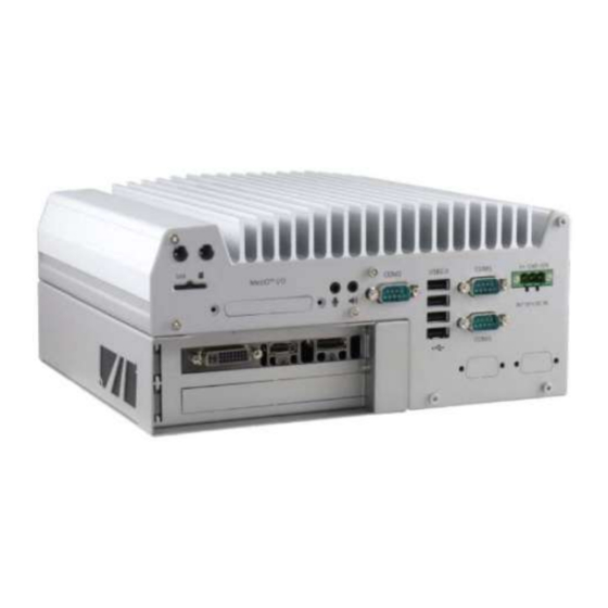
Nuvo-5095GC Series User’s Manual 2.2 Front Panel I/O Functions On Nuvo-5095GC series, plenty of I/O functions are provided on front panel and back panel so you can easily access them. Most common computer I/O functions are placed on the front panel. In this section, we’ll illustrate each I/O function on the front panel. -
Page 14: Reset Button
Nuvo-5095GC Series User’s Manual 2.2.2 Reset Button The reset button is used to manually reset the system in case of any abnormal condition. To avoid unexpected operation, the reset button is hidden behind the front panel. You need to use a pin-like object to push the reset button. -
Page 15: Gigabit Ethernet Port
Nuvo-5095GC Series User’s Manual 2.2.4 Gigabit Ethernet Port Nuvo-5095GC series offers 6 GbE ports on its front panel. The GbE port marked in blue is ® ® designed with Intel I219-LM and ports marked in red are implemented with Intel I210-IT Gigabit Ethernet controllers. -
Page 16: Remote On/Off Control And Status Led Output
For an application which places Nuvo-5095GC controller inside a cabinet, it’s useful to control the on/off of the system via an external switch, as well as check how the system’s running via some external LED indicators. Nuvo-5095GC series provides a 2x5, 2.0mm pitch wafer connector on the front panel for this purpose. -
Page 17: Usb 3.0 Connectors
LED indicator. 2.2.6 USB 3.0 Connectors Nuvo-5095GC series offers four USB 3.0 (SuperSpeed USB) ports on its front panel. They are implemented by native xHCI (eXtensible Host Controller Interface) controller in Q170 chipset and are compatible with USB 3.0, USB 2.0, USB 1.1 and USB 1.0 devices. -
Page 18: Dvi/Hdmi Connectors
Nuvo-5095GC Series User’s Manual 2.2.7 DVI/HDMI Connectors Nuvo-5095GC series has multiple display outputs on its front panel for connecting different displays according to your system configuration. DVI/HDMI transmits graphics data in digital format and therefore can deliver better image quality at high resolution. The DVI/HDMI connector on the front panel can either output DVI signals or HDMI signal depending on the display device connected. -
Page 19: Vga Connector
VGA connector is the most popular way for connecting a display. The VGA output on Nuvo-5095GC series supports up to 1920 x 1200 resolution. By BIOS default and hardware implementation, the VGA output is always enabled even when VGA monitor is not connected. -
Page 20: Displayport
Nuvo-5095GC Series User’s Manual 2.2.9 DisplayPort Nuvo-5095GC series has multiple display outputs on its front panel for connecting different displays according to your system configuration. Two DisplayPort (DP) connectors are available for high-resolution graphics outputs. They can deliver 4096 x 2304 resolution when single DP port is used or 2880 x 1800 resolution when both DP ports are simultaneously used. -
Page 21: Back Panel I/O Functions
2.3.1 3-Pin Terminal Block for DC and IGN Input Nuvo-5095GC series allows a wide range of DC power input from 8 to 35V via a 3-pin pluggable terminal block, which is fit for field usage where DC power is usually provided. -
Page 22: Com Ports (Com1 / Com2 / Com3)
Nuvo-5095GC Series User’s Manual 2.3.2 COM Ports (COM1 / COM2 / COM3) Nuvo-5095GC series provides three COM ports for communicating with external devices. COM1, COM2 and COM3 are located on the back panel via 9-pin D-Sub male connectors. They are implemented using industrial-grade ITE8786 Super IO chip (-40 to 85°C) and provide up to 115200 bps baud rate. -
Page 23: Usb2.0 Connectors
Nuvo-5095GC Series User’s Manual 2.3.3 USB2.0 Connectors In addition to USB 3.0, Nuvo-5095GC Series provides four USB 2.0 ports on the back panel. They are implemented by native xHCI (eXtensible Host Controller Interface) controller in Q170 chipset and are compatible with USB 2.0, USB 1.1 and USB 1.0 devices. Legacy USB support is also provided so you can use USB keyboard/mouse in DOS environment. -
Page 24: Mezio Tm I/O Connector
I/O function. To support MezIO I/O connectivity, Nuvo-5095GC series reserves the cutting hole for a SCSI-II 68-pin connector on its back panel. Please refer to section 2.5 for information of MezIO interface and section 3.6 for installing a MezIO module. -
Page 25: Internal I/O Functions
Nuvo-5095GC Series User’s Manual 2.4 Internal I/O Functions In addition to I/O connectors on the front/back panel, Nuvo-5095GC series provides other features via its on-board connectors, such as SATA ports, mini-PCIe sockets, internal USB ports and MezIO interface. In this section, we’ll illustrate these internal I/O functions. -
Page 26: Msata / Mini-Pcie #1 Dual-Mode Socket
Nuvo-5095GC Series User’s Manual 2.4.2 mSATA / mini-PCIe #1 Dual-Mode Socket Nuvo-5095GC series provides two mini-PCIe sockets compliant with mini-PCIe specification rev. 1.2. The first socket supports mini-PCIe and mSATA dual mode operation. You can install either a mSATA SSD or mini-PCIe module into this socket. The system automatically detects and configures it to run PCIe or SATA signals according to installed module. - Page 27 Nuvo-5095GC Series User’s Manual The following table describes the pin definition of mSATA/mini-PCIe #1 dual-mode socket. Pin # Signal (mPCIe) Signal (mSATA) Pin # Signal (mPCIe) Signal (mSATA) WAKE# +3.3Vaux +3.3Vaux COEX1 COEX2 +1.5V +1.5V CLKREQ# UIM_PWR UIM_DATA REFCLK- UIM_CLK...
-
Page 28: Mini-Pcie #2 Socket
2.4.3 Mini-PCIe #2 Socket Nuvo-5095GC series provides two mini-PCIe sockets compliant with mini-PCIe specification rev. 1.2. The second mini-PCie socket works with the panel-accessible SIM slot. There are plenty of off-the-shelf mini-PCIe modules with versatile capabilities. By installing a mini-PCIe module, your system can have expanded features such as WIFI, GPS, CAN bus, analog frame grabber and etc. - Page 29 Nuvo-5095GC Series User’s Manual The following table describes the pin definition of mini-PCIe #2 socket. Pin # Signal Pin # Signal WAKE# +3.3Vaux COEX1 COEX2 +1.5V CLKREQ# UIM_PWR UIM_DATA REFCLK- UIM_CLK REFCLK+ UIM_RESET UIM_VPP Mechanical Key Reserved* (UIM_C8) Reserved* (UIM_C4)
-
Page 30: Internal Sata Port #1
2.4.4 Internal SATA Port #1 Nuvo-5095GC series provides two SATA ports which support Gen3, 6 Gb/s SATA signals. Each SATA port is composed of a 7-pin SATA connector and a 4-pin power connector. SATA port #1 is used in conjunction with the HDD bracket to accommodate the first 2.5”... -
Page 31: Internal Sata Port #2
Nuvo-5095GC Series User’s Manual 2.4.5 Internal SATA Port #2 Nuvo-5095GC series provides two SATA ports which support Gen3, 6 Gb/s SATA signals. Each SATA port is composed of a 7-pin SATA connector and a 4-pin power connector. SATA port #2 is used in conjunction with the HDD bracket to accommodate the second 2.5”... -
Page 32: Internal Usb Port
Nuvo-5095GC Series User’s Manual 2.4.6 Internal USB Port Nuvo-5095GC series provides one additional USB port internally on the PCBA. It supports standard USB 2.0 signals. You can utilize this USB port to connect a USB protection dongle inside the chassis of Nuvo-5095GC controller. -
Page 33: Mezio Tm Interface
Nuvo-5095GC Series User’s Manual 2.5 MezIO Interface MezIO is an innovative interface designed for integrating application-oriented I/O functions into an embedded system. It offers computer signals, power rails and control signals via a high-speed connector. MezIO is also mechanically reliable benefited from its 3-point mounted mezzanine structure. - Page 34 Nuvo-5095GC Series User’s Manual Function Function Signal Signal Description Description Reserved Reserved PCIE_TXP_0 PCIe data pair Reserved Reserved PCIE_TXN_0 PCIe data pair Reserved Reserved Ground Reserved Reserved PCIE_RXP_0 PCIe data pair System S4 signal SLP_S4# PCIE_RXN_0 PCIe data pair Ground...
-
Page 35: Mezio Module For Nuvo-5095Gc Series
Currently you can have more RS-232/422/485 ports, isolated digital I/O or ignition power control by installing the following module into your Nuvo-5095GC controller. Neousys will continuously develop MezIO modules with versatile features for Nuvo-5095GC series and other embedded products. Model... - Page 36 Nuvo-5095GC Series User’s Manual 16-CH isolated DI and 16-CH isolated MezIO-D230-50 DO MezIO module 16-mode ignition power control MezIO MezIO-V20 module (Nuvo-5095GCLP only) Copyright © 2017 Neousys Technolgy Inc. All Right Reserved.
-
Page 37: Expansion Cassette For Gpu
GPU and exhaust hot air by system fan, and makes Nuvo-5095GC extremely reliable when operating at at 60°C with 100% GPU loading. The expansion Cassette of Nuvo-5095GC series accepts graphics cards of dual-slot width with up to 75W TDP. Currently nVidia GTX 950 and GTX 1050 are the recommended GPU models for Nuvo-5095GC series. -
Page 38: Inside The Cassette Of Nuvo-5095Gc
Nuvo-5095GC Series User’s Manual 2.6.1 Inside the Cassette of Nuvo-5095GC The expansion Cassette of Nuvo-5095GC series contains a backplane with a x16 PCI Express connector. It runs 8-lanes, Gen3 PCIe signals to provide a maximal 8 GB/s bandwidth. It supports up to 7A@12V rated current (84 watts) for a PCIe graphics card. -
Page 39: Mechanical Dimension
Nuvo-5095GC Series User’s Manual 2.7 Mechanical Dimension 2.7.1 Top View of Nuvo-5095GC Series Copyright © 2017 Neousys Technolgy Inc. All Right Reserved. -
Page 40: Front View Of Nuvo-5095Gc Series
Nuvo-5095GC Series User’s Manual 2.7.2 Front View of Nuvo-5095GC Series 2.7.3 Side View of Nuvo-5095GC Series Copyright © 2017 Neousys Technolgy Inc. All Right Reserved. -
Page 41: Bottom View Of Nuvo-5095Gc Series
Nuvo-5095GC Series User’s Manual 2.7.4 Bottom View of Nuvo-5095GC Series Copyright © 2017 Neousys Technolgy Inc. All Right Reserved. -
Page 42: Chapter 3 Getting Start
Nuvo-5095GC controller. Disassemble your Nuvo-5095GC Controller In prior to install components such as CPU, memory and HDD to Nuvo-5095GC series, you need to disassemble Nuvo-5095GC controller and expose the PCBA. Please cautiously follow the procedures described here to prevent any damage on your Nuvo-5095GC controller. - Page 43 Nuvo-5095GC Series User’s Manual Remove the bottom cover of Nuvo-5095GC controller. You can see the PCBA exposed. Copyright © 2017 Neousys Technolgy Inc. All Right Reserved.
-
Page 44: Install And Replace Lga1151 Cpu
LGA socket when CPU is absent. 3.2.1 Install a CPU on Nuvo-5095GC For a Nuvo-5095GC series barebone (without CPU installed), please follow steps described below to install a CPU on it. Follow steps described in section 3.1 to disassemble the Nuvo-5095GC controller. - Page 45 Nuvo-5095GC Series User’s Manual Place the PCBA on a flat surface. Remove the plastic protective cover from the LGA1151 socket. Caution When the protective cover is removed and LGA1151 socket is exposed, please carefully handle the PCBA to avoid any damage on LGA socket.
- Page 46 Nuvo-5095GC Series User’s Manual Get the CPU retaining bracket from the accessory box and place it on the top of CPU. The CPU retaining bracket shall be screwed from the opposite side. Please hold the CPU and bracket firmly while turning the PCBA upside down, and secure the CPU retaining bracket with two M3 P-head screws.
- Page 47 Nuvo-5095GC Series User’s Manual Put the PCBA back to heat-sink. Make sure all the screw holes on PCBA are aligned with mounting posts of the heat-sink. Get five M3 spring screws from the accessory box. Fix them according to the order indicated on the photo (red circles).
-
Page 48: Replace The Cpu On Nuvo-5095Gc
Nuvo-5095GC Series User’s Manual 3.2.2 Replace the CPU on Nuvo-5095GC For a Nuvo-5095GC system with CPU installed, please follow steps described below to replace the CPU on it. Caution Please make sure the PCBA/heat-sink assembly is cooled down to room temperature before you proceed with the installation/replacement procedures. - Page 49 Nuvo-5095GC Series User’s Manual Gently lift the PCBA from the heat-sink. The CPU and CPU retaining bracket shall stay with the heat-sink. Caution When the PCBA is detached and LGA1151 socket is exposed, please carefully handle the PCBA to avoid any damage on LGA socket.
- Page 50 Nuvo-5095GC Series User’s Manual Check the condition of thermal pads on the heat-sink, especially the thermal pad for CPU. If it’s broken, please replace it with a new one. Follow steps described in step 4 to step 8 in section 3.2.1 to install a new CPU to your Nuvo-5095GC controller.
-
Page 51: Install Ddr4 Sodimm Module
Nuvo-5095GC Series User’s Manual 3.3 Install DDR4 SODIMM Module Nuvo-5095GC series provides two 260-pin, SODIMM sockets for installing DDR4 memory modules. It supports maximal 32GB capacity by installing two 16 GB DDR4-2133 SODIMM modules. You can install/replace DDR4 SODIMM modules by following the steps described in this section. -
Page 52: Install 2.5" Sata Hdd/Ssd
Nuvo-5095GC Series User’s Manual 3.4 Install 2.5” SATA HDD/SSD Nuvo-5095GC series has two SATA ports for connecting SATA HDD or SSD drives. They are used in conjunction with the HDD bracket on the trap-door to accommodate two 2.5” HDD/SSD. Please follow instructions described in this section to install SATA HDD/SSD to your Nuvo-5095GC controller. - Page 53 Nuvo-5095GC Series User’s Manual Pull out the SATA cable inside the chassis and connect it to HDD/SSD. Place the HDD/bracket assembly back to the bottom cover. And fix it with three M3 flat-head screws. Copyright © 2017 Neousys Technolgy Inc. All Right Reserved.
-
Page 54: Install Mini-Pcie Module
Nuvo-5095GC Series User’s Manual 3.5 Install Mini-PCIe Module Nuvo-5095GC series provides two full-size mini-PCIe sockets with SIM card support. You can install off-the-shelf mini-PCIe modules to expand functions for Nuvo-5095GC controller. In this section, we demonstrate how to install a mini-PCIe 3G module and its antenna to the Nuvo-5095GC controller. - Page 55 Nuvo-5095GC Series User’s Manual Attach the IPEX-to-SMA cable to the 3G module. Fix the SMA connector of the IPEX-to-SMA cable to one of the four antenna apertures on either front panel of back panel. Recover the front panel, back panel and the bottom cover and attach a 3G antenna to the SMA connector.
-
Page 56: Install Mezio Tm Module
Nuvo-5095GC Series User’s Manual 3.6 Install MezIO Module Nuvo-5095GC series is designed with Neousys’ MezIO interface. You can install a MezIO module to expand application-oriented I/O function. In this section, we demonstrate the procedure of installing Neousys MezIO-C180 to add eight additional COM ports to your Nuvo-5095GC controller. - Page 57 Nuvo-5095GC Series User’s Manual Remove the pre-cutting plate of MezIO I/O aperture on the back panel to expose the SCSI-II 68-pin connector of the MezIO-C180 module. Copyright © 2017 Neousys Technolgy Inc. All Right Reserved.
-
Page 58: Install Nvidia® Graphics Card In Cassette
Nuvo-5095GC Series User’s Manual Install nVidia® Graphics Card in Cassette The expansion Cassette is designed to accommodate nVidia® GTX 950 and GTX 1050 graphics card. To get best thermal stability for GPU operation, please install either industrial-grade graphics card provided by Neousys or consumer-grade graphics card listed in section 1.4. - Page 59 Nuvo-5095GC Series User’s Manual 2.5 mm PORON® form 10 mm PORON® form Stick PORON® form strips to the specific positions of Cassette cover. Get four pieces of rubber spacers from the accessory box. The spacers are used to support graphics card when installed. Stick the rubber spacers to the back side of the graphics card.
- Page 60 Nuvo-5095GC Series User’s Manual Fix the graphics card using two M3, PW-head screws. Recover the Cassette cover and fix it with three M3, flat-head screws. And put Expansion Cassette back to Nuvo-5095GC controller, and fix it using four M4 screws.
-
Page 61: Mount Your Nuvo-5095Gc
Nuvo-5095GC Series User’s Manual 3.8 Mount your Nuvo-5095GC Nuvo-5095GC series features a patented mechanical design which creates sealed tunnel for intake air flow. To obtain best efficiency for heat dissipation, it’s required to keep enough clearance beneath the bottom side of Nuvo-5095GC controller. Nuvo-5095 series is shipped with stand-off brackets which can create 20 mm clearance. - Page 62 Nuvo-5095GC Series User’s Manual Place Nuvo-5095GC controller on a flat surface and fix it with screws. You can also take advantage of the keyhole-shaped holes of mounting brackets to suspend the Nuvo-5095GC controller on the Wall. For the case of wall-mounting, please mount your Nuvo-5095GC controller in a right direction for better efficiency of heat dissipation.
-
Page 63: Connect Dc Power To Your Nuvo-5095Gc
Slotted screwdriver. Caution Nuvo-5095GC series accepts 8~35 VDC when using terminal block for DC input. Please make sure the voltage and polarity of DC power is correct before you connect it to Nuvo-5095GC controller. Supplying a voltage over 35V or incorrect polarity will damage the system. -
Page 64: Power On Your Nuvo-5095Gc Controller
For an application which places Nuvo-5095GC controller inside a cabinet, it’s useful to control the on/off of the system using an external switch. Nuvo-5095GC series provides a 2x5, 2.0mm pitch wafer connector (for detail, please refer to section 2.2.5) for connecting a non-latched switch and behaves ATX-mode power on/off control. -
Page 65: Power On Nuvo-5095Gc Using Wake-On-Lan Function
Power on Nuvo-5095GC Using Wake-on-LAN Function Wake-on-LAN (WOL) is a mechanism to wake up a computer system from a S5 (system off with standby power) state via issuing a magic packet. Nuvo-5095GC series implements the Wake-on-LAN function for the GbE port marked below. - Page 66 Wake on Magic Packet Nuvo-5095GC series can wake from S5 state when receiving a magic packet. The magic packet is a broadcast frame containing anywhere within its payload 6 bytes of all 255 (FF FF FF FF FF FF in hexadecimal), followed by sixteen repetitions of...
- Page 67 Nuvo-5095GC Series User’s Manual the target computer's 48-bit MAC address. For example, NIC’s 48-bit MAC Address is 78h D0h 04h 0Ah 0Bh 0Ch DESTINATION SOURCE MISC FF FF FF FF FF FF 78 D0 04 0A 0B 0C 78 D0 04 0A 0B 0C...
-
Page 68: Chapter 4 Bios And Driver
Chapter 4 BIOS and Driver 4.1 BIOS Settings Nuvo-5095GC series is shipped with factory-default BIOS settings cautiously programmed for best performance and compatibility. In this section, we’ll illustrate some of BIOS settings you may need to modify. Please always make sure you understand the effect of change before you proceed with any modification. -
Page 69: Com Port Configuration
Nuvo-5095GC Series User’s Manual 4.1.1 COM Port Configuration There are totally five COM ports implemented on Nuvo-5095GC series. COM1, COM2 and COM3 are located on the back panel. COM4 and COM5 are internally used for MezIO interface. COM1 and COM3 of Nuvo-5095GC series support RS-232 (full-duplex), RS-422 (full-duplex) and RS-485 (half-duplex) mode, while COM2 supports RS-232 mode only. -
Page 70: Sata Port Configuration
Nuvo-5095GC Series User’s Manual 4.1.2 SATA Port Configuration The SATA controller of Nuvo-5095GC series supports two operating modes: AHCI and RAID mode. AHCI mode, which exposes SATA's advanced capabilities such as hot swapping and native command queuing, is supported in most of modern operating systems. -
Page 71: Enable Tpm Feature
4.1.3 Enable TPM Feature TPM, or Trusted Platform Module, is a hardware-based cryptoprocessor to secure hardware by integrating cryptographic keys into devices. Nuvo-5095GC series is designed with on-board TPM 2.0 module. As TPM 2.0 requires 64-bit Windows 7/8/10 with UEFI boot mode, it is disable in BIOS by default. -
Page 72: Configure Cpu Sku Power
Nuvo-5095GC Series User’s Manual 4.1.4 Configure CPU SKU Power Nuvo-5095GC series supports a long list of 6 -gen Skylake LGA1151 CPU with up to 65W TDP. A unique feature, “SKU Power Config” is implemented in BIOS to allow users to specify user-defined SKU power limit for installed CPU according to deployment environment and power budget. -
Page 73: Wake-On-Lan Option
Nuvo-5095GC Series User’s Manual 4.1.5 Wake-on-LAN Option Wake-on-LAN (WOL) is a mechanism which allows you to turn on your Nuvo-5095GC controller via Ethernet connection. To utilize Wake-on-LAN function, you need to enable this option first in BIOS settings. Please refer to section 3.10.3 for instructions of using WOL function. -
Page 74: Power On After Power Failure Option
Nuvo-5095GC Series User’s Manual 4.1.6 Power On after Power Failure Option The “Power On after Power Failure” option defines the behavior of Nuvo-5095GC controller when DC power is supplied. Value Description S0 – Power On System is powered on when DC power is supplied. -
Page 75: Configure Legacy/Uefi Boot Type
Nuvo-5095GC Series User’s Manual 4.1.7 Configure Legacy/UEFI Boot Type Nuvo-5095GC series supports both legacy and UEFI boot mode. UEFI, or Unified Extensible Firmware Interface, is a specification proposed by Intel to define a software interface between operating system and platform firmware. Most modern operating systems, such as Windows 7/8/10 and Linux, support both legacy and UEFI boot mode. -
Page 76: Position New Boot Device
Nuvo-5095GC Series User’s Manual 4.1.8 Position New Boot Device When you plug a newly-installed boot device (e.g. USB flash disk), this option allow you determine whether to place the new boot device in the first place or the last place in the boot sequence. -
Page 77: Watchdog Timer For Booting
Nuvo-5095GC Series User’s Manual 4.1.9 Watchdog Timer for Booting The BIOS of Nuvo-5095GC series has a useful feature which allows users to use the watchdog timer to secure the booting process. You can specify the timeout value for watchdog timer. Once the watchdog timer expires, the BIOS issues a reset command to initiate another booting process. - Page 78 Nuvo-5095GC Series User’s Manual Copyright © 2017 Neousys Technolgy Inc. All Right Reserved.
-
Page 79: Select A Boot Device
Nuvo-5095GC Series User’s Manual 4.1.10 Select a Boot Device When you have multiple bootable devices connected to your Nuvo-5095GC controller (e.g. HDD, mSATA, USB flash disk, USB DVD-drive), you may need to select one of them as the boot device. There are two ways to select the device. You can either, press F12 when system boots up to go to Boot Manager and then select one of the devices, or select the boot device in BIOS settings. -
Page 80: Configure Amt
4.2 Configure AMT Intel® AMT (Active Management Technology) is a hardware-based technology for remotely managing target PCs via Ethernet connection. Nuvo-5095GC series supports AMT function via its Ethernet port implemented with Intel I219-LM. In prior to use AMT to remotely control Nuvo-5095GC series, you need to configure AMT password and network settings. -
Page 81: Configure Raid Volume
Nuvo-5095GC Series User’s Manual 4.3 Configure RAID Volume Nuvo-5095GC series supports RAID function implemented by Q170 PCH for more reliable and efficient disk access. The built-in RAID supports RAID 0 (data stripping), RAID 1 (data mirroring), RAID 5 (data stripping + parity) and RAID 10 (data stripping + mirroring). You can configure RAID mode according to your application by following steps listed below. -
Page 82: Operating System Support
Nuvo-5095GC Series User’s Manual 4.4 Operating System Support Nuvo-5095GC series supports most modern operating systems developed for Intel® x86 architecture. The following list contains the operating systems which have been tested with Nuvo-5095GC series in Neousys Technology Inc. Microsoft Window 7 32-bit* ... -
Page 83: Driver Installation
Install All Drivers Using “One-Click” Driver Installation Insert the “Drivers & Utilities DVD” into a USB DVD-drive attached to your Nuvo-5095GC series. A setup utility launches and the following dialog appears. Click on the “Automatic Driver Installation”. The setup utility will automatically detect your Windows operating system and install all necessary drivers. -
Page 84: Install Drivers Manually
Nuvo-5095GC Series User’s Manual 4.5.2 Install Drivers Manually You can also manually install each driver for Nuvo-5095GC series. Please refer to the following information about installing drivers for different operating system. Windows 7 32-bit The recommended driver installation sequence is Chipset driver (x:\Driver_Pool\Chipset_10_Series\Win_ALL\SetupChipset.exe) - Page 85 Nuvo-5095GC Series User’s Manual LAN driver (x:\Driver_Pool\GbE_I210_I350\Win_ALL_64\APPS\PROSETDX\Winx64\DxSetup.exe) ME driver (x:\Driver_Pool\ME_10_Series\Win_ALL_AMT\SetupME.exe) Copyright © 2017 Neousys Technolgy Inc. All Right Reserved.
-
Page 86: Install Driver For Wdt And Per-Port Poe On/Off Control
You should install the driver package (WDT_DIO_Setup.exe) in prior to use these functions. Please note that you must install WDT_DIO_Setup_v2.2.4 or later revision for Nuvo-5095GC series. Windows 7 32-bit Please execute the driver setup program in the following directory. -
Page 87: Appendix A Install Windows 7 On Nuvo-5095Gc
Nuvo-5095GC Series User’s Manual Appendix A Install Windows 7 on Nuvo-5095GC Intel Skylake platform removes EHCI controller and supports USB 2.0 and USB 3.0 connectivity only through its xHCI controller. For Windows 8/8.1 and Windows10, no issue is anticipated due to native xHCI support in the OS. However, Windows 7 does not natively support xHCI thus manual installation of Intel’s xHCI driver is required to support both USB... -
Page 88: Step 2 - Create Usb Flash Drive Installer From .Iso
Nuvo-5095GC Series User’s Manual Step 2 - Create USB flash drive installer from .ISO The next step is to create a bootable USB flash drive using the .iso file created in step 1. Here we use Microsoft Windows USB/DVD Download Tool to create the USB flash drive (https://www.microsoft.com/en-us/download/windows-usb-dvd-download-tool). -
Page 89: Step 3 - Create Working Folder On Your Local Drive
Nuvo-5095GC Series User’s Manual Step 3 - Create working folder on your local drive In this step, we need to create a working folder on your local drive and copy necessary files to it. Please following the steps below. 1. Create a temporary working folder on your local drive. Here we use D:\WIM as an example. -
Page 90: Step 4 - Execute Batch File To Patch .Wim Files
Nuvo-5095GC Series User’s Manual Step 4 - Execute batch file to patch .wim files To support xHCI for Windows 7 installation, both install.wim and boot.wim need to be patched to include xHCI driver files. Neousys offers Windows-based batch files (Win7_USB3_Patch_x86.bat for Windows 7 32-bit and Win7_USB3_Patch_x64.bat for Windows 7 64-bit) to simplify this process. -
Page 91: Step 5 - Install Windows 7 Using Usb Flash Drive Installer
Nuvo-5095GC Series User’s Manual The batch file will automatically patch both install.wim and boot.wim. It takes few minutes to finish the patch process. Once patch finished, please overwrite the \sources\install.wim and \sources\boot.wim in USB flash drive installer with the patched ones. -
Page 92: Appendix B Using Watchdog Timer
In this section, we’ll illustrate how to use the function library provided by Neousys to program the WDT functions. Currently, WDT driver library supports Windows 7/8.1/10 32-bit and 64-bit versions. For other OS support, please contact Neousys Technology for further information. - Page 93 Nuvo-5095GC Series User’s Manual To install WDT_DIO_Setup package, please follow steps described below. Execute WDT_DIO_Setup.2.2.20.exe. The following dialog appears. Click “Next >” and specify the directory of installing related files. The default directory is C:\Neousys\WDT_DIO. Copyright © 2017 Neousys Technolgy Inc. All Right Reserved.
- Page 94 Nuvo-5095GC Series User’s Manual Once the installation is finished, a dialog appears to prompt you to reboot the system. The WDT & DIO library will take effect after system rebooting. When you programming your WDT or DIO program, the related files are located in...
-
Page 95: Wdt Function Reference
Nuvo-5095GC Series User’s Manual WDT Function Reference InitWDT Syntax BOOL InitWDT(void); Description Initialize the WDT function. You should always invoke InitWDT() before set or start watchdog timer. Parameter None Return Value Returns TRUE if initialization successes, FALSE if initialization failed. - Page 96 Nuvo-5095GC Series User’s Manual StartWDT Syntax BOOL StartWDT(void); Description Start countdown of WDT. When WDT is started, the WDT LED indicator starts to blink in a frequency of 1Hz. If no ResetWDT() or StopWDT is invoked before WDT is counted to 0, the WDT expires and system resets.
- Page 97 Nuvo-5095GC Series User’s Manual Always returns TRUE; Usage BOOL bRet = StopWDT() Copyright © 2017 Neousys Technolgy Inc. All Right Reserved.
Need help?
Do you have a question about the Nuvo-5095GC Series and is the answer not in the manual?
Questions and answers