Advertisement
Quick Links
Zone Interface Module (ZIM)
Installation Guide
1 Pre installation
Installation must conform to applicable local installation codes
!
and should only be installed by a fully trained competent person.
•
Ensure that the device is installed as per the site survey.
•
The use of a non-metallic spacer should be considered if mounting the
device on to a metal surface.
•
DO NOT press the log on button on a pre-programmed device, as this
will cause communication with the control panel to be lost. Should this
happen, delete the device from the system and add it back on.
•
This device contains electronics that may be susceptible to damage
from Electrostatic Discharge (ESD). Take appropriate precautions when
handling electronic boards.
3 Mounting location guidelines
For
optimum
performance, the following
must be observed:
•
Ensure the ZIM is not installed
within 0.6 m of the WZM.
•
Ensure the ZIM is not installed
within 2 m of the control panel
or any other wireless or electrical
equipment.
•
Ensure the ZIM is not installed
within 0.6 m of any metal work.
4 Remove cable entry points
•
Drill
the
cable
entry
points
as
necessary.
•
Cable
glands
should be used.
•
DO
NOT
leave
excess cable in the
device.
©2022 EMS Ltd. All rights reserved.
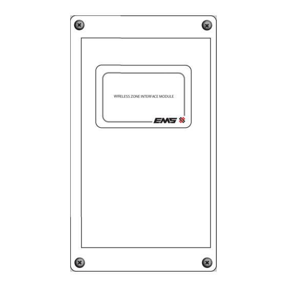
WIRELESS ZONE INTERFACE MODULE
wireless
WZM
Existing
control panel
DO NOT use
Available cable
entry points
Part no
EC-41-0200
2 Components
0.6 m
POWER
WIRELESS ZONE INTERFACE MODULE
FAULT
WIRELESS ZONE MONITOR
0.6 m
2 m
FIRE
Fire Alarm Control
5 Fix to the wall
•
Use all four circled
fixing
=
ensure a firm fixing.
•
Use suitable fasteners
and fixings.
=
Fixing position location
within cavity
Page 1 of 2
Product description
Wireless Zone Interface Module
1
2
1
4x lid fixing screws,
2
Front lid,
ZIM
POWER
FAULT
WZM
WIRELESS ZONE MONITOR
FIRE
Existing
control panel
Fire Alarm Control
positions
to
3
IDENT REV DATE
3
Back box
WIRELESS ZONE INTERFACE MODULE
ZIM
LOGON
ANTENNA
012ABC
KEEP CABLES AWAY FROM THIS AREA
01
1
2
4
8
16
32
64
CLOSED
F-SAFE
LED
ENABLE
FAULT
INPUT 1I NPUT 2
EXPAN2
OUTPUT 1
OUTPUT
2
EXPAN1
IP- IP+ IP- IP+
3VDC SET RST
3VDC SET RST
N/OC OM N/C
N/OC OM N/C
TSD142-99 Issue 7 21/06/2022 AJM
Advertisement

Related Manuals for EMS EC-41-0200


Summary of Contents for EMS EC-41-0200
- Page 1 Available cable device. IP- IP+ IP- IP+ 3VDC SET RST 3VDC SET RST N/OC OM N/C N/OC OM N/C entry points Fixing position location within cavity ©2022 EMS Ltd. All rights reserved. Page 1 of 2 TSD142-99 Issue 7 21/06/2022 AJM...
- Page 2 EN54-25:2008. Incorporating corrigenda September 2010 and March 2012. Fire detection and fire alarm systems. IP rating IP65 European Union EMS declares that this device is in compliance with Directive Operating frequency 868 MHz Directives 2014/53/EU. The full text of the EU declaration of conformity is available at the following internet address: www.
Need help?
Do you have a question about the EC-41-0200 and is the answer not in the manual?
Questions and answers