Table of Contents
Advertisement
Quick Links
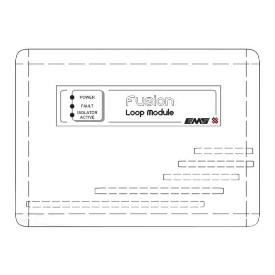
Loop Module
Installation Guide
1 Pre installation
Installation must conform to applicable local installation codes
!
and should only be installed by a fully trained competent person.
•
Ensure the loop module is installed as per the site survey.
•
Refer to step 3 to ensure optimised wireless performance.
•
If using remote aerials with this product, refer to the remote aerial
installation guide (MK293) for more information.
•
A maximum of 5 loop modules can be connected per loop.
•
This device contains electronics that may be susceptible to damage
from Electrostatic Discharge (ESD). Take appropriate precautions when
handling electronic boards.
3 Mounting location guidelines
For
optimum
performance, the following
must be observed:
•
Ensure
the
loop
module is not installed
within 2 m of other
wireless or electrical
equipment
(not
including the control
panel).
•
Ensure
the
loop
module is not installed
within 0.6 m of metal
work.
5 Remove cable entry points
•
Drill the cable entry
points as necessary.
= DO NOT use
= Available cable
entry points
©2024 EMS Ltd. All rights reserved.
F F usion
usion
POWER
FAULT
ISOLATOR
ACTIVE
wireless
2 m
0.6 m
Loop
POWER
FAULT
ACTIVE
ISOLATOR
module
FIRE
Control
panel
Fire Alarm Control
Part no
Description
FCX-532-001
Fusion Loop Module
2 Components
1
2
3
1
4x corner covers,
4
Loop module PCB,
4 Optional PCB removal
•
Remove the three circled retaining screws, before unclipping the PCB.
ISOLATE
6 Fix to the wall
•
All five circled fixing
positions are available
for use as required.
•
The key hole can also
be used for locating
and
fixing
where
required.
Page 1 of 2
4
2
4 x lid screws,
3
Loop module lid,
5
Loop module back box
ON
12
34
56
78
TX
RX
1 2 3 4 5 6 7
RADIO
RESET
0V
RX
HELP
TX
3V
POWER
FAULT
WD
BACK
LOOP IN
LOOP OUT
-
-
TSD077-99 (Issue 9) 10/01/2024 AJM
5
Advertisement
Table of Contents

Subscribe to Our Youtube Channel
Related Manuals for EMS Fusion FCX-532-001


Summary of Contents for EMS Fusion FCX-532-001
- Page 1 • The key hole can also be used for locating fixing where required. = DO NOT use = Available cable entry points ©2024 EMS Ltd. All rights reserved. Page 1 of 2 TSD077-99 (Issue 9) 10/01/2024 AJM...
- Page 2 March 2012. Fire detection and fire alarm systems. Output transmitter power 0 to 14 dBm (0 to 25 mW) European Union EMS declares that this device is in compliance with Directive Directives 2014/53/EU. The full text of the EU declaration of conformity is Signalling protocol available at the following internet address: www.emsgroup.co.uk...
Need help?
Do you have a question about the Fusion FCX-532-001 and is the answer not in the manual?
Questions and answers