Table of Contents
Advertisement
Quick Links
Advertisement
Table of Contents

Related Manuals for Goulds Pumps 3642


Summary of Contents for Goulds Pumps 3642
- Page 1 Installation, Operation, and Maintenance Instructions 3642-3656...
-
Page 3: Table Of Contents
2.1 General Information........................... 8 3 Installation................................9 3.1 Installation ..............................9 4 Operation................................10 4.1 Operation..............................10 5 Maintenance – Model 3642 ..........................11 5.1 Maintenance – Model 3642 ........................11 6 Replacing Mechanical Seal ..........................12 6.1 Dismantling.............................. 12 6.2 Reassembly............................. 13 7 Maintenance-Model 3656 .......................... -
Page 4: Introduction And Safety
ITT Goulds pumps will provide safe, trouble-free service when properly installed, maintained, and operat- Safe installation, operation, and maintenance of ITT Goulds Pumps equipment are an essential end user responsibility. This Pump Safety Manual identifies specific safety risks that must be considered at all times during product life. -
Page 5: Safety
Trapped liquid can rapidly expand and result in a violent explosion and injury. ITT Goulds Pumps will not accept responsibility for physical injury, damage, or delays caused by a failure to observe the instructions for installation, operation, and maintenance contained in this Pump Safety Manual or the current IOM available at http://www.gouldspumps.com/literature. -
Page 6: General Precautions
Personal injuries will result if procedures outlined in this manual are not followed. ITT Goulds Pumps will not accept responsibility for physical injury, damage or delays caused by a failure to observe the instructions in this manual and the IOM provided with your equip- ment. - Page 7 WARNING Shutdown, Disassembly, and Reassembly: Pump components can be heavy. Proper methods of lifting must be employed to avoid physical injury and/or equipment damage. Steel toed shoes must be worn at all times. 3642-3656 Installation, Operation, and Maintenance Instructions...
-
Page 8: Atex Considerations And Intended Use
Special care must be taken in potentially explosive environments to ensure that the equipment is proper- ly maintained. This includes but is not limited to: Monitoring the pump frame and liquid end temperature. Maintaining proper bearing lubrication. Ensuring that the pump is operated in the intended hydraulic range. 3642-3656 Installation, Operation, and Maintenance Instructions... -
Page 9: Parts
Maintenance manual (IOM) can cause serious personal injury or damage to the equipment. This in- cludes any modification to the equipment or use of parts not provided by ITT Goulds Pumps. If there is any question regarding the intended use of the equipment, please contact an ITT Goulds representative before proceeding. -
Page 10: General Information
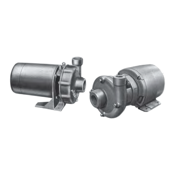
2 General Information 2.1 General Information Models 3642 and 3656 both are single state end suction volute type general purpose centrifugal pumps with enclosed impellers applicable to clear liquids. Also appropriate for general machinery and industrial services up to 212°F particularly suited to air conditioning condensate booster service and water transfer. -
Page 11: Installation
All single phase motors furnished with model 3642 pumps are dual voltage, 115/230V, 60 Hz. A.C. All pumps are tested at the factory. Upon installation in the field correct rotation (3 phase), phase frequency and voltage of power supply should be checked. -
Page 12: Operation
For possible leaks, check flange bolting, piping connections and pipe plugs. Tighten if necessary. The maximum temperature - 212° F limitation – is imposed by the mechanical seal material. Optional, high temperature seals might be used. 3642-3656 Installation, Operation, and Maintenance Instructions... -
Page 13: Maintenance - Model 3642
Inspect periodically to determine the condition of the lubricant and how often it should be replaced. Ball-bearing construction (A.O. Smith, Century) Double shielded, prelubricated bearings are used. For the life of the bearings no additional lubrication is required. 3642-3656 Installation, Operation, and Maintenance Instructions... -
Page 14: Replacing Mechanical Seal
To loosen impeller, it might be required to apply heat to exposed shaft thread and impeller hub since Loctite was used to secure impeller in place. Figure 2: 3642-3656 Installation, Operation, and Maintenance Instructions... -
Page 15: Reassembly
Also take extra care not to damage the seal lapped faces. Spray both shaft and impeller threads with LOCQUIC, Primer "T" –Loctite product item No. 74756 (Purchased at Automotive Parts or Hardware store). Let parts dry and then apply Loctite #271 on same parts. 3642-3656 Installation, Operation, and Maintenance Instructions... - Page 16 13. Replace motor shaft end cap or end cover. 14. Close all drain openings using pipe joint compound on male threads. 15. Reprime before starting. Do not start unit until pump is completely filled with water. 3642-3656 Installation, Operation, and Maintenance Instructions...
-
Page 17: Maintenance-Model 3656
10. Inspect shaft sleeve if damaged, remove from shaft by heating with torch and using a bearing puller or other similar device. Reassembly: Clean parts and male and female locks seal seat counterbore and shaft in particular shaft where sleeve fits (if sleeve was removed). 3642-3656 Installation, Operation, and Maintenance Instructions... - Page 18 22. Check for free rotation after assembly is completed. 23. Close all drain openings using pipe joint compound on male threads. 24. Reprime before starting. Do not start unit until pump is completely filled with water. 3642-3656 Installation, Operation, and Maintenance Instructions...
- Page 19 Visit our website for the latest version of this document and more information: www.gouldspumps.com ITT - Goulds Pumps Vertical Products Operation 3951 Capitol Avenue City of Industry, CA 90601-1734 Form IOM.3642-3656.en-US.2023-05 ©2023 ITT Corporation The original instruction is in English. All non-English instructions are translations of the original instruction.
Need help?
Do you have a question about the 3642 and is the answer not in the manual?
Questions and answers