Table of Contents
Advertisement
Quick Links
Advertisement
Table of Contents
Troubleshooting

Related Manuals for Goulds Pumps 3180


Summary of Contents for Goulds Pumps 3180
- Page 1 Installation, Operation, and Maintenance Manual Models 3180, 3181, 3185, and 3186...
-
Page 3: Table Of Contents
4.4.3 Alignment measurement guidelines ....................41 4.4.4 Attach the dial indicators for alignment ..................41 4.4.5 Pump-to-driver alignment instructions................... 42 4.5 Grout the baseplate..........................45 4.6 Bypass-piping considerations........................46 Models 3180, 3181, 3185, and 3186 Installation, Operation, and Maintenance Manual... - Page 4 5.8.4 Connection of sealing liquid for a packed stuffing box ..............72 5.8.5 Seal the shaft with a packed stuffing box..................72 5.8.6 Dynamic-seal option (3180 and 3185 S, M, L, and XL groups only)..........74 5.9 Install the shaft guard - if provided ......................75 5.10 Pump priming ............................
- Page 5 6.3 Shaft-seal maintenance........................... 85 6.3.1 Mechanical-seal maintenance....................... 85 6.3.2 Packed stuffing-box maintenance ....................86 6.3.3 Dynamic seal maintenance (3180 and 3185 S, M, L, and XL groups only) ........86 6.4 Disassembly ............................88 6.4.1 Disassembly precautions ......................88 6.4.2 Tools required..........................89 6.4.3 Drain the pump..........................
- Page 6 9.1 Putting pump out of operation ....................... 171 9.2 Disposal..............................171 10 Other Relevant Documentation or Manuals....................172 10.1 For additional documentation ......................172 11 Local ITT Contacts ............................173 11.1 Regional offices ........................... 173 Models 3180, 3181, 3185, and 3186 Installation, Operation, and Maintenance Manual...
-
Page 7: Introduction And Safety
This manual clearly identifies accepted methods for disassembling units. These methods must be adhered to. Never apply heat to aid in their removal unless explicitly stated in this manual. Models 3180, 3181, 3185, and 3186 Installation, Operation, and Maintenance Manual... -
Page 8: Safety Terminology And Symbols
A hazardous situation which, if not avoided, will result in death or seri- ous injury WARNING: A hazardous situation which, if not avoided, could result in death or serious injury Models 3180, 3181, 3185, and 3186 Installation, Operation, and Maintenance Manual... -
Page 9: Electrical Hazard
Handle and dispose of the processed liquid in compliance with applicable environmental regula- tions. • Clean up all spills in accordance with safety and environmental procedures. • Report all environmental emissions to the appropriate authorities. Models 3180, 3181, 3185, and 3186 Installation, Operation, and Maintenance Manual... -
Page 10: Electrical Installation
Consider limiting personnel’s exposure time to noise or, where possible, en- closing equipment to reduce noise. Local law may provide specific guidance regarding expo- sure of personnel to noise and when noise exposure reduction is required. Models 3180, 3181, 3185, and 3186 Installation, Operation, and Maintenance Manual... -
Page 11: Precautions Before Work
Beware of the starting jerk, which can be powerful. • Rinse the components in water after you disassemble the pump. • Do not exceed the maximum working pressure of the pump. Models 3180, 3181, 3185, and 3186 Installation, Operation, and Maintenance Manual... -
Page 12: Hazardous Liquids
Genuine Goulds Pumps parts are used. • Only Ex-approved spare parts and accessories authorized by ITT are used in Ex-approved prod- ucts. Limitations The warranty does not cover faults caused by these situations: Models 3180, 3181, 3185, and 3186 Installation, Operation, and Maintenance Manual... -
Page 13: Ex Considerations And Intended Use
• Do not open the product while it is energized or in an explosive gas atmosphere. Models 3180, 3181, 3185, and 3186 Installation, Operation, and Maintenance Manual... - Page 14 Maintenance manual (IOM) can cause serious personal injury or damage to the equipment. This in- cludes any modification to the equipment or use of parts not provided by ITT Goulds Pumps. If there is any question regarding the intended use of the equipment, please contact an ITT Goulds representative before proceeding.
- Page 15 If there is any question regarding these require- ments or if the equipment is to be modified, please contact a Goulds representative be- fore proceeding. Models 3180, 3181, 3185, and 3186 Installation, Operation, and Maintenance Manual...
- Page 16 Ex classification of the equipment. Failure to follow these procedures will void the Ex clas- sification for the equipment. Bearing replacement intervals are given in the specific pump model IOM. Models 3180, 3181, 3185, and 3186 Installation, Operation, and Maintenance Manual...
- Page 17 ITT should be consulted in this context. • Move equipment to a safe/non Ex environment for repairs/adjustments or use spark re- sistant tools and work methods. Models 3180, 3181, 3185, and 3186 Installation, Operation, and Maintenance Manual...
- Page 18 1.4 Ex Considerations and Intended Use Models 3180, 3181, 3185, and 3186 Installation, Operation, and Maintenance Manual...
-
Page 19: Transportation And Storage
Risk of serious personal injury or equipment damage. Proper lifting practices are critical to safe transport of heavy equipment. Ensure that practices used are in compliance with all applicable regulations and standards. Models 3180, 3181, 3185, and 3186 Installation, Operation, and Maintenance Manual... - Page 20 Use slings through clevises attached to baseplate lifting lugs plate lifting lugs Examples Figure 3: Example of a proper lifting method - centerline discharge Figure 4: Example of a proper lifting method - tangential discharge Models 3180, 3181, 3185, and 3186 Installation, Operation, and Maintenance Manual...
- Page 21 Do not use this method to lift a Polyshield ANSI Combo with the pump and motor mounted. These items are not designed to handle the heavy weight of the Polyshield system. Doing so may result in equipment damage. Models 3180, 3181, 3185, and 3186 Installation, Operation, and Maintenance Manual...
-
Page 22: Storage Guidelines
You can purchase long-term storage treatment with the initial unit order or you can purchase it and apply it after the units are already in the field. Contact your local ITT sales representative. Models 3180, 3181, 3185, and 3186 Installation, Operation, and Maintenance Manual... -
Page 23: Frostproofing
The pump is frostproof. Immersed in a liquid The pump is frostproof. Lifted out of a liquid into a temperature below freezing The impeller might freeze. Sitting idle The pump might freeze. Models 3180, 3181, 3185, and 3186 Installation, Operation, and Maintenance Manual... -
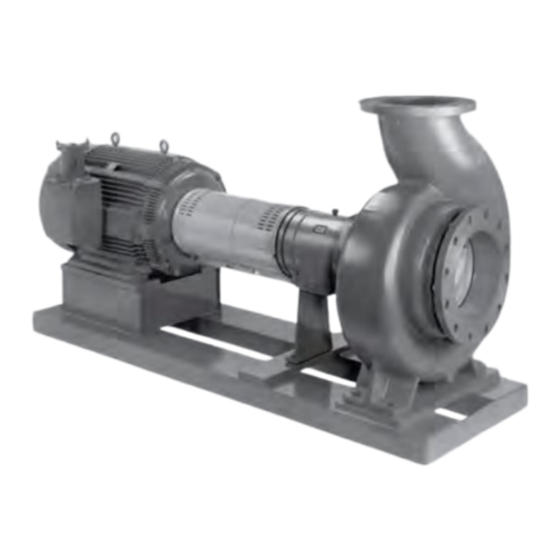
Page 24: Product Description
3 Product Description 3 Product Description 3.1 General description The 3180 models are horizontal, end-suction, centrifugal pumps designed for heavy-duty process appli- cations. Figure 8: Model of 3180 and 3185 Figure 9: Model of 3181 and 3186 3.1.1 Part description... - Page 25 The cover functions both as a way to seal the chamber and as a replaceable wear part. It is secured with a series of clamping lugs at the outside diameter of models 3180 and 3185, and it is through-bolted with capscrews on models 3181 and 3186.
- Page 26 The bearing frame cooling can be supplied as an option with oil lubrication. • The bearing locknut and coupling extension are dimensioned in inches for models 3180 and in milli- meters for models 3185 and 3186. For the XL1, XL1-S1, XL1-S2, XL2-S and XL2 groups: •...
-
Page 27: Direction Of Rotation
One end is free to expand with possible temperature variations. • A PTFE O-ring prevents leaks under the sleeve. • The sleeve is dimensioned in inches for models 3180 and 3181 and in millimeters for models 3185 and 3186. For the XL1, XL1-S1, XL1-S2, XL2-S and XL2 groups: •... -
Page 28: Nameplate Information
Table 4: Explanation of nameplate on the pump casing Nameplate field Explanation IMPLR. DIA. Impeller diameter, in inches MAX. DIA. Maximum impeller diameter, in inches Rated pump flow, in gallons per minute Models 3180, 3181, 3185, and 3186 Installation, Operation, and Maintenance Manual... - Page 29 SER. NO. Serial number of the pump @20 °C Kilograms per square centimeter at 20°C MAX. DSGN KG/CM Nameplate on the bearing frame Figure 12: Nameplate on the bearing frame Models 3180, 3181, 3185, and 3186 Installation, Operation, and Maintenance Manual...
- Page 30 Ensure the pump driver and all other auxiliary components meet the required area classifica- tion at the site. If they are not compatible, do not operate the equipment and contact an ITT representative before proceeding. Models 3180, 3181, 3185, and 3186 Installation, Operation, and Maintenance Manual...
-
Page 31: Installation
If the pump location is overhead, undertake special Consider a consultation with a noise specialist. precautions to reduce possible noise transmission. Models 3180, 3181, 3185, and 3186 Installation, Operation, and Maintenance Manual... -
Page 32: Foundation Requirements
Sleeve-type bolts Item Description Baseplate Shims Foundation Sleeve Bolt Figure 15: Sleeve type bolts J-type bolts Item Description Baseplate Shims or wedges Foundation Bolt Figure 16: J-type bolts Models 3180, 3181, 3185, and 3186 Installation, Operation, and Maintenance Manual... -
Page 33: Baseplate-Mounting Procedures
Figure 18: Side view Lower the baseplate carefully onto the foundation bolts. Put the machinist's levels across the mounting pads of the driver and the mounting pads of the pump. Models 3180, 3181, 3185, and 3186 Installation, Operation, and Maintenance Manual... -
Page 34: Install The Baseplate Using Jackscrews
Make sure that the distance between the baseplate and the foundation surface is between 19 mm | 0.75 in. and 38 mm | 1.50 in. Make sure that the center jackscrews do not touch the foundation surface yet. Models 3180, 3181, 3185, and 3186 Installation, Operation, and Maintenance Manual... - Page 35 Use the baseplate-leveling worksheet when you take the readings. Item Description Machinist's levels Driver's mounting pads Foundation bolts Jackscrews Grout hole Pump's mounting pads Figure 20: Level driver mounting pads Models 3180, 3181, 3185, and 3186 Installation, Operation, and Maintenance Manual...
-
Page 36: Spring Mounted Installation
The spring-mounted baseplate is designed only to support piping loads from thermal expan- sion. Ensure that the suction and discharge piping are supported individually. Failure to do so may result in equipment damage. Determine which spring-mounted baseplate you are working with: Models 3180, 3181, 3185, and 3186 Installation, Operation, and Maintenance Manual... - Page 37 Install a spring follower with the flat bottom facing upward. m) Install a flat washer on the stud. Install a hex nut and a hex jam nut on the stud. Models 3180, 3181, 3185, and 3186 Installation, Operation, and Maintenance Manual...
- Page 38 316 stainless steel plates, which have a 63 to 125 micro-inch surface finish. • Make sure that the foundation pads are correctly installed on the foundation/floor. See the instruc- tions from the manufacturer. Models 3180, 3181, 3185, and 3186 Installation, Operation, and Maintenance Manual...
- Page 39 Lower the baseplate so that the spring assemblies fit into the foundation pads. The weight of the baseplate compresses the springs, which leaves the upper nuts loose. You might have to level the baseplate by adjusting the X1 and X2 dimensions. Models 3180, 3181, 3185, and 3186 Installation, Operation, and Maintenance Manual...
- Page 40 Fasten the lower and upper hex jam nuts against the hex nuts on each spring assembly. Make notes of X1 and X2 dimensions in the GA dimension drawing for future reference. Models 3180, 3181, 3185, and 3186 Installation, Operation, and Maintenance Manual...
-
Page 41: Baseplate-Leveling Worksheet
4.2 Baseplate-mounting procedures 4.2.5 Baseplate-leveling worksheet Level measurements 1)____________________ 2)____________________ 3)____________________ 4)____________________ 5)____________________ 6)____________________ 7)____________________ 8)____________________ 9)____________________ 10)___________________ 11)___________________ 12)___________________ 13)___________________ 14)___________________ 15)___________________ 16)___________________ 17)___________________ 18)___________________ Models 3180, 3181, 3185, and 3186 Installation, Operation, and Maintenance Manual... -
Page 42: Install The Pump, Driver, And Coupling
Final alignment (hot alignment) checks When After the first run This ensures correct alignment when both the pump and the driver are at op- erating temperature. Models 3180, 3181, 3185, and 3186 Installation, Operation, and Maintenance Manual... -
Page 43: Permitted Indicator Values For Alignment Checks
Attach one indicator (P) so that the indicator rod comes into contact with the perimeter of the driver coupling half (Y). This indicator is used to measure parallel misalignment. Models 3180, 3181, 3185, and 3186 Installation, Operation, and Maintenance Manual... -
Page 44: Pump-To-Driver Alignment Instructions
Add shims in order to raise the feet of the driver at the other end. Shims Figure 23: Side view of an incorrect vertical alignment Repeat the previous steps until the permitted reading value is achieved. Models 3180, 3181, 3185, and 3186 Installation, Operation, and Maintenance Manual... -
Page 45: Perform Angular Alignment For A Horizontal Correction
The pump coupling half (X) is higher than the driver coupling half (Y). Add shims of a thickness equal to half of the indicator reading value to each driver foot. Models 3180, 3181, 3185, and 3186 Installation, Operation, and Maintenance Manual... -
Page 46: Perform Parallel Alignment For A Horizontal Correction
Make sure to slide the driver evenly. Failure to do so can negatively affect horizontal angular correction. Figure 26: Top view of an incorrect horizontal alignment Repeat the previous steps until the permitted reading value is achieved. Models 3180, 3181, 3185, and 3186 Installation, Operation, and Maintenance Manual... -
Page 47: Perform Complete Alignment For A Vertical Correction
When you pour the grout, remove air bubbles from it by using one of these methods: • Puddle with a vibrator. • Pump the grout into place. Allow the grout to set. Models 3180, 3181, 3185, and 3186 Installation, Operation, and Maintenance Manual... -
Page 48: Bypass-Piping Considerations
You can size and install a minimum-flow orifice in a bypass line in order to prevent bypassing excessive flows. Consult your ITT representative for assistance in sizing a minimum-flow orifice. Models 3180, 3181, 3185, and 3186 Installation, Operation, and Maintenance Manual... -
Page 49: Piping Checklists
Keep the piping as short as possible. This helps to minimize friction losses. Keep the piping as straight as possi- This helps to minimize friction losses. ble. Avoid unnecessary bends. Use Models 3180, 3181, 3185, and 3186 Installation, Operation, and Maintenance Manual... - Page 50 In no case should the loads on the pump flanges exceed the limits de- scribed in the information provided with the order. Models 3180, 3181, 3185, and 3186 Installation, Operation, and Maintenance Manual...
-
Page 51: Fastening
(elbow, valve, strainer, or expansion See the Example sections for illustrations. joint) is at least five pipe diameters. Models 3180, 3181, 3185, and 3186 Installation, Operation, and Maintenance Manual... - Page 52 If the pump is not self-priming, check that a Use a foot valve with a diameter that is at least equiva- device for priming the pump is installed. lent to the diameter of the suction piping. Models 3180, 3181, 3185, and 3186 Installation, Operation, and Maintenance Manual...
- Page 53 NOTICE: This illustration shows an incor- NOTICE: rectly installed elbow. This illustration shows a correctly installed elbow. Models 3180, 3181, 3185, and 3186 Installation, Operation, and Maintenance Manual...
-
Page 54: Discharge Piping Checklist
Inspection and maintenance of the pump • Reduce risk of pumpage vaporization and vapor locking at low flow rates for low specific gravity liq- uids. See Example: Discharge piping equipment for illustra- tions. Models 3180, 3181, 3185, and 3186 Installation, Operation, and Maintenance Manual... -
Page 55: Auxiliary-Piping Checklist
Auxiliary cooling and flush systems must be operating properly to prevent excess heat generation, sparks, and/or premature failure. Ensure auxiliary piping is installed as specified on the pump data sheet prior to startup. Models 3180, 3181, 3185, and 3186 Installation, Operation, and Maintenance Manual... -
Page 56: Final Piping Checklist
Re-check the alignment to make sure that If pipe strain exists, then correct the piping. pipe strain has not caused any misalign- ment. Models 3180, 3181, 3185, and 3186 Installation, Operation, and Maintenance Manual... -
Page 57: Commissioning, Startup, Operation, And Shutdown
Running a pump without safety devices exposes operators to risk of serious personal in- jury or death. Never operate a unit unless appropriate safety devices (guards, etc.) are properly installed. Models 3180, 3181, 3185, and 3186 Installation, Operation, and Maintenance Manual... -
Page 58: Remove The Coupling Guard
Remove the bolt from the u-nut located on the driver half of the coupling guard. Remove the driver half of the coupling guard: Slightly spread the bottom apart. Lift upwards. Models 3180, 3181, 3185, and 3186 Installation, Operation, and Maintenance Manual... -
Page 59: Check The Rotation
Make sure that the coupling hubs are fastened securely to the shafts. Make sure that the coupling spacer is removed. The pump ships with the coupling spacer removed. Unlock power to the driver. Models 3180, 3181, 3185, and 3186 Installation, Operation, and Maintenance Manual... -
Page 60: Impeller-Clearance Check
0.033 0.8 0.094 2.4 12X12-14 0.028 0.7 0.087 2.2 6X8-16 0.028 0.7 0.087 2.2 0.015 0.38 0.018 0.46 0.02 0.51 0.022 0.56 0.026 0.66 4X6-19 0.028 0.7 0.087 2.2 Models 3180, 3181, 3185, and 3186 Installation, Operation, and Maintenance Manual... - Page 61 0.023 0.58 0.025 0.64 0.027 0.69 0.031 0.79 XL1-S2 20X18-19E 0.072 1.8 0.133 3.4 10X14-22E 0.135 3.4 0.188 4.8 0.015 0.38 0.018 0.46 0.02 0.51 0.022 0.56 0.026 0.66 Models 3180, 3181, 3185, and 3186 Installation, Operation, and Maintenance Manual...
- Page 62 0.035 0.89 0.038 0.97 0.04 1.02 0.042 1.07 0.046 1.17 XL2-S 20X24-31 24X28-35E 0.133 3.4 0.202 5.1 0.03 0.76 0.033 0.84 0.035 0.89 0.037 0.94 0.041 1.04 24X30-35 24X30-35A Models 3180, 3181, 3185, and 3186 Installation, Operation, and Maintenance Manual...
-
Page 63: Check The Shearpeller™ Axial Clearance
Impeller clearance methods You can set the impeller clearance with either of these methods: • Dial indicator method • Feeler gauge method Models 3180, 3181, 3185, and 3186 Installation, Operation, and Maintenance Manual... -
Page 64: Set The Impeller Clearance - Dial Indicator Method
Lock out the driver power and remove the coupling guard. Loosen the jam nuts (423B) on the jack bolts (371A), and then back the bolts out about two turns. Models 3180, 3181, 3185, and 3186 Installation, Operation, and Maintenance Manual... -
Page 65: Couple The Pump And Driver
Electrical connections must be made by certified electricians in compliance with all inter- national, national, state, and local rules. • Refer to driver/coupling/gear manufacturer's installation and operation manuals (IOM) for specific instructions and recommendations. Models 3180, 3181, 3185, and 3186 Installation, Operation, and Maintenance Manual... -
Page 66: Install The Coupling Guard
Refer to driver/coupling/gear manufacturer's installation and operation manuals (IOM) for specific instructions and recommendations. WARNING: The coupling guard used in an Ex classified environment must be properly certified and con- structed from a spark resistant material. Models 3180, 3181, 3185, and 3186 Installation, Operation, and Maintenance Manual... - Page 67 The annular groove in the guard is located around the end plate. Position the opening (flange) so that it does not interfere with the piping but still allows for ac- cess when you install the bolts. Models 3180, 3181, 3185, and 3186 Installation, Operation, and Maintenance Manual...
- Page 68 Figure 33: Annular groove in coupling guard Place one washer over the bolt and insert the bolt through the round hole at the front end of the guard half. Models 3180, 3181, 3185, and 3186 Installation, Operation, and Maintenance Manual...
- Page 69 Figure 35: Placement of driver half of coupling guard Place the end plate over the driver shaft and locate the end plate in the annular groove at the rear of the coupling guard half. Models 3180, 3181, 3185, and 3186 Installation, Operation, and Maintenance Manual...
- Page 70 Figure 37: Slide driver-half of coupling guard towards motor Repeat Steps 4 through 6 for the center slots in the coupling guard. 12. Tighten all nuts on the guard assembly. Models 3180, 3181, 3185, and 3186 Installation, Operation, and Maintenance Manual...
-
Page 71: Bearing Lubrication
82°C | 180°F ISO grade ISO viscosity grade 68 ISO viscosity grade 100 Approximate SSU at 38°C | 100°F DIN 51517 C100 Kinematic viscosity at 40°C | 105°F /sec Models 3180, 3181, 3185, and 3186 Installation, Operation, and Maintenance Manual... -
Page 72: Acceptable Oil For Lubricating Bearings
If plant environments or requirements are not suitable for vented bearing frames, then do not use the Watchdog oiler. Install the Watchdog oiler in the connection for the sight glass. The oiler does not require any setting dimensions. Models 3180, 3181, 3185, and 3186 Installation, Operation, and Maintenance Manual... -
Page 73: Greased-For-Life Bearing Lubrication
Run the piping so that the pump pushes the pumped fluid from the casing and injects it into the seal gland. If necessary, an external heat exchanger cools the pumped fluid before it enters the seal gland. Models 3180, 3181, 3185, and 3186 Installation, Operation, and Maintenance Manual... -
Page 74: Packed Stuffing Box Option
| 15 psi above the stuffing box pressure. 5.8.5 Seal the shaft with a packed stuffing box WARNING: • Packed stuffing boxes are not allowed in an Ex-classified environment. Models 3180, 3181, 3185, and 3186 Installation, Operation, and Maintenance Manual... - Page 75 Insert the packing and stagger the joints in each ring by 90°. Install the stuffing-box parts in this order: Two packing rings One lantern ring (two-piece) Three packing rings Models 3180, 3181, 3185, and 3186 Installation, Operation, and Maintenance Manual...
-
Page 76: Dynamic-Seal Option (3180 And 3185 S, M, L, And Xl Groups Only)
Failure to do so may result in decreased performance. Install the gland halves and evenly hand-tighten the nuts . 5.8.6 Dynamic-seal option (3180 and 3185 S, M, L, and XL groups only) WARNING: Dynamic seals are not allowed in an Ex-classified environment. -
Page 77: Install The Shaft Guard - If Provided
Slowly open the suction isolation valve. Open the air vents on the suction and discharge piping until the pumped fluid flows out. (Also open casing vent on tangential discharge models). Close the air vents. Models 3180, 3181, 3185, and 3186 Installation, Operation, and Maintenance Manual... -
Page 78: Prime The Pump With The Suction Supply Below The Pump
Use a foot valve and an outside source of liquid in order to prime the pump. The liquid can come from one of these sources: • A priming pump • A pressurized discharge line • Another outside supply Close the discharge isolation valve. Models 3180, 3181, 3185, and 3186 Installation, Operation, and Maintenance Manual... -
Page 79: Other Methods Of Priming The Pump
Risk of equipment damage due to dry operation. Immediately observe the pressure gauges. If discharge pressure is not quickly attained, stop the driver immediately, reprime, and attempt to restart the pump. Models 3180, 3181, 3185, and 3186 Installation, Operation, and Maintenance Manual... -
Page 80: I-Alert® Equipment Health Monitor
General considerations WARNING: • Risk of serious personal injury or property damage. Dry running may cause rotating parts within the pump to seize to non-moving parts. Do not run dry. Models 3180, 3181, 3185, and 3186 Installation, Operation, and Maintenance Manual... - Page 81 Failure to do so can cause liquid to freeze and damage the pump. Note that different liquids freeze at different temperatures. Some pump designs do not drain completely and may require flushing with a liquid that doesn't freeze. Models 3180, 3181, 3185, and 3186 Installation, Operation, and Maintenance Manual...
-
Page 82: Shut Down The Pump
Check the alignment while the unit is still hot. Refer to 4.4 Pump-to-driver alignment on page 40 in the Installation chapter. Reinstall the coupling guard. Restart the pump and driver. Models 3180, 3181, 3185, and 3186 Installation, Operation, and Maintenance Manual... -
Page 83: Maintenance
Change the oil every three months (2000 operating hours) at minimum. • Check the shaft alignment, and realign as required. Annual inspections Perform these inspections one time each year: • Check the pump capacity. • Check the pump pressure. Models 3180, 3181, 3185, and 3186 Installation, Operation, and Maintenance Manual... -
Page 84: Bearing Maintenance
ISO viscosity grade 100 Approximate SSU at 38°C | 100°F DIN 51517 C100 Kinematic viscosity at 40°C | 105°F /sec 6.2.1.1 Oil volumes Oil volume requirements Frame Quarts Liters Models 3180, 3181, 3185, and 3186 Installation, Operation, and Maintenance Manual... -
Page 85: Lubricating-Grease Requirements
-15°C to 110°C | 5°F to 230°F Use a lithium-based mineral-oil grease with a consistency of NLGI 2. Exceed 110°C | 230°F Use a high-temperature grease. Mineral-oil greases should have oxidation stabilizers and a consistency of NGLI 3. Models 3180, 3181, 3185, and 3186 Installation, Operation, and Maintenance Manual... -
Page 86: Regrease The Grease-Lubricated Bearings
Failure to do so can result in impurities entering the bearing housing while re- greasing the bearings. Wipe dirt from the grease fittings. Remove the two grease-relief plugs from the bottom of the frame. Models 3180, 3181, 3185, and 3186 Installation, Operation, and Maintenance Manual... -
Page 87: Lubricate The Bearings After A Shutdown Period
The seal drawing specifies the required flush fluid and attachment points. Before you start the pump Check the seal and all flush piping. Models 3180, 3181, 3185, and 3186 Installation, Operation, and Maintenance Manual... -
Page 88: Packed Stuffing-Box Maintenance
Over-tightening can cause excessive wear and power consumption during operation. If you cannot tighten the packing to obtain less than the specified leakage rate, then replace the packing. 6.3.3 Dynamic seal maintenance (3180 and 3185 S, M, L, and XL groups only) - Page 89 One repeller drain connection The lantern ring connection can be used to inject flush liquid or grease when required on specific appli- cations, but not when using a diaphragm seal. Models 3180, 3181, 3185, and 3186 Installation, Operation, and Maintenance Manual...
-
Page 90: Disassembly
CAUTION: • Avoid injury. Worn pump components can have sharp edges. Wear appropriate gloves while handling these parts. Models 3180, 3181, 3185, and 3186 Installation, Operation, and Maintenance Manual... -
Page 91: Tools Required
Drain the liquid from the piping and flush the pump if it is necessary. Disconnect all auxiliary piping and tubing. Remove the coupling guard. Remove the coupling guard. Disconnect the coupling. Models 3180, 3181, 3185, and 3186 Installation, Operation, and Maintenance Manual... -
Page 92: Remove The Back Pull-Out Assembly
Personal Protective Equipment (PPE, such as steel-toed shoes, gloves, etc.) at all times. Seek assistance if necessary. 370A Figure 42: 3180 and 3185 S, M, L, and XL group Models 3180, 3181, 3185, and 3186 Installation, Operation, and Maintenance Manual... - Page 93 6.4 Disassembly Figure 43: 3180 and 3185 XL1, XL1-S1, XL1-S2, XL2-S, and XL2 group Figure 44: 3181 and 3186 Pump Remove the hold-down bolts of the bearing frame. Remove the back pull-out assembly from the casing: Models 3180, 3181, 3185, and 3186 Installation, Operation, and Maintenance Manual...
-
Page 94: Remove The Casing Wear Ring (S, M, L, And Xl)
Remove the hex nuts (357A) from the casing wear ring studs (356E). Remove the casing wear ring (164) from the casing (100) using a pry bar in the slot provided, if nec- essary. Remove the casing wear ring gasket (360P). Models 3180, 3181, 3185, and 3186 Installation, Operation, and Maintenance Manual... -
Page 95: Remove The Suction Sideplate
This procedure only applies to models that have an open impeller or a Shearpeller Remove the hex nuts (357A) from the sideplate studs (356E). Remove the sideplate (176) from the casing (100) using a pry bar in the provided slot. Models 3180, 3181, 3185, and 3186 Installation, Operation, and Maintenance Manual... -
Page 96: Impeller Removal
6.4.8.1 Remove an open impeller Secure the back pull-out assembly firmly to the workbench. Lock the shaft (122) to prevent turning. Remove the impeller nut (304) and O-ring (412A). Models 3180, 3181, 3185, and 3186 Installation, Operation, and Maintenance Manual... - Page 97 Pry the impeller off of the shaft using two bars opposite of each other. Place them between the cov- er and the impeller shroud. You can also use an impeller puller. Models 3180, 3181, 3185, and 3186 Installation, Operation, and Maintenance Manual...
- Page 98 Secure the back pull-out assembly firmly to the workbench. Lock the shaft (122) to prevent turning. Remove the Shearpeller nut (304), O-ring (412A), and Shearpeller sleeve (126A). Pry bar (above) Pry bar (below) Models 3180, 3181, 3185, and 3186 Installation, Operation, and Maintenance Manual...
-
Page 99: Shaft Guard Removal (If Provided)
Do not remove the clip that retains the bolt on the guard to maintain a captive fastener. Retain each guard half with fasteners for reinstallation. Item Description Mounting bolt Figure 45: Shaft guard removal Models 3180, 3181, 3185, and 3186 Installation, Operation, and Maintenance Manual... -
Page 100: Remove The Stuffing Box Cover
If required, gently tap the Sizes: 18x14-16E cover from the frame adapter using a soft-blow hammer on the dry side of the cover. 20x18-19E Models 3180, 3181, 3185, and 3186 Installation, Operation, and Maintenance Manual... - Page 101 6.4 Disassembly Figure 46: S, M, L, and XL Figure 47: XL1, XL2-S, and XL2 Models 3180, 3181, 3185, and 3186 Installation, Operation, and Maintenance Manual...
-
Page 102: Remove The Taperbore Plus™ Seal Chamber
Sleeve puller. 6.4.11 Remove the TaperBore PLUS™ seal chamber WARNING: Seal chambers are heavy. Use proper support to avoid personal injury. Re-engage the setting clips on the mechanical seal. Models 3180, 3181, 3185, and 3186 Installation, Operation, and Maintenance Manual... - Page 103 If required, gently tap the cov- 20x18-19E er from the frame adapter using a soft-blow hammer on the dry side of the cover. Models 3180, 3181, 3185, and 3186 Installation, Operation, and Maintenance Manual...
- Page 104 6.4 Disassembly Figure 49: S, M, L, and XL Figure 50: XL1, XL2-S, and XL2 Models 3180, 3181, 3185, and 3186 Installation, Operation, and Maintenance Manual...
- Page 105 (184). If the spacer ring (217) is not loose, gently tap the sides of the ring with a soft-blow hammer until loose. Lift off the spacer ring (217). Models 3180, 3181, 3185, and 3186 Installation, Operation, and Maintenance Manual...
-
Page 106: Remove The Dynamic Seal
WARNING: Covers are heavy, use the proper support to avoid personal injury. This procedure only applies to the 3180 and 3185 pump models. Remove box-to-backplate nuts (357J). Remove the backplate (444) by tapping on the end of the studs with soft-faced hammer. -
Page 107: Remove The Frame Adapter From The Frame (Xl1, Xl1-S1, Xl1-S2, Xl2-S, And Xl2)
Remove the eight hex head bolts (370B) from the frame adapter (108). Gently tap the frame adapter from the frame (228) using a soft-blow hammer on the dry side of the frame adapter. Models 3180, 3181, 3185, and 3186 Installation, Operation, and Maintenance Manual... - Page 108 Gently tap the frame adapter from the frame (228) using a soft-blow hammer on the dry side of the frame adapter. Figure 54: XL1-S1 and XL1-S2 (pump sizes 18x14-16E, 20x18-19E) Models 3180, 3181, 3185, and 3186 Installation, Operation, and Maintenance Manual...
-
Page 109: Disassemble The Bearing Frame
Tap the impeller end of the shaft with a soft-face hammer to assist in removal. Rotating element. Remove the thrust-bearing retainer ring (253B) by removing the socket-head cap screws (236A) Slide the thrust-bearing housing (134A) off of the thrust bearings. Models 3180, 3181, 3185, and 3186 Installation, Operation, and Maintenance Manual... -
Page 110: Guidelines For I-Alert® Equipment Health Monitor Disposal
Now install the top adjusting nut and jam nut. Tighten finger tight. Repeat steps one through four for all the spring assemblies. Once all the springs have been installed, lower the unit on to the foundation pads. Models 3180, 3181, 3185, and 3186 Installation, Operation, and Maintenance Manual... -
Page 111: Disassemble The Spring-Mounted Baseplate (Second Generation)
Make sure all the springs are positively locked against free expansion. Raise the baseplate and support it so the mounting brackets for the spring assemblies are approxi- mately 16 in. (406 mm) above the foundation/floor. Models 3180, 3181, 3185, and 3186 Installation, Operation, and Maintenance Manual... -
Page 112: Preassembly Inspections
Plain washer Stud Baseplate mounting bracket Follower Spring Follower Plain washer Hex nut Hex jam nut Bearing pad assembly Figure 56: Exploded view of the spring assembly 6.5 Preassembly inspections Models 3180, 3181, 3185, and 3186 Installation, Operation, and Maintenance Manual... -
Page 113: Replacement Guidelines
Ensure appropriate use of fasteners during installation or reassembly of the unit. • Use fasteners of the proper size and material only. • Replace all corroded fasteners. Models 3180, 3181, 3185, and 3186 Installation, Operation, and Maintenance Manual... -
Page 114: Bearing-Frame Inspection
Tighten the bearing locknut firmly with a spanner wrench while you clamp the bearing set against the shaft shoulder. Bend the tang of lockwasher into a slot on the bearing locknut. Models 3180, 3181, 3185, and 3186 Installation, Operation, and Maintenance Manual... - Page 115 (3.05 to 4.06 mm) between the retaining ring and (4.06 to 5.33 mm) between the retaining ring and bearing housing. bearing housing. Assembled rotating element: Prepare the bearing frame for either grease or oil lubrication. Models 3180, 3181, 3185, and 3186 Installation, Operation, and Maintenance Manual...
- Page 116 Make sure that the oil return is fully open (no plug). bricat- Oil return Grease Make sure that the plug (370E) is installed in the radial end oil return. lubri- cated Models 3180, 3181, 3185, and 3186 Installation, Operation, and Maintenance Manual...
- Page 117 Lightly lubricate the bearing bores (outer diameter of radial bearing), thrust bearing housing, and O- ring with grease or light oil. Carefully insert the rotating element into the bearing frame. Rotating element Orient the bearing housing depending on the lubrication. Models 3180, 3181, 3185, and 3186 Installation, Operation, and Maintenance Manual...
- Page 118 These measurements show the gap after you set the impeller: • 0.25 in. (6.35 mm) on the S and M frames • 0.38 in. (9.65 mm) on the XL1, XL1-S1, XL1-S2, XL2-S, and XL2 frames Models 3180, 3181, 3185, and 3186 Installation, Operation, and Maintenance Manual...
- Page 119 One on the left side of the frame (228) • One at the stuffing box end at the top of the frame Install two plugs (408C and 408D) on the right side of the frame (228). Models 3180, 3181, 3185, and 3186 Installation, Operation, and Maintenance Manual...
-
Page 120: Assemble The Frame Adapter To The Frame
Smaller frame adapters may have only one tapped hole and require only one eye bolt. Install the frame adapter (108) to the frame using eight hex head bolts (370B) as shown below. Models 3180, 3181, 3185, and 3186 Installation, Operation, and Maintenance Manual... - Page 121 Install the frame adapter (108) to the frame using four hex head bolts (370B) as shown below. Figure 58: XL1-S1 and XL1-S2 (pump sizes 18x14-16E, 20x18-19E) Models 3180, 3181, 3185, and 3186 Installation, Operation, and Maintenance Manual...
-
Page 122: Assemble The Taperbore Plus™ Seal Chamber
Assemble the seal chamber (184) to the bearing frame using eight hex head bolts (370B). XL1, XL2-S, Assemble the seal chamber (184) to the frame adapter (108) using two hex head bolts (370H). and XL2 Models 3180, 3181, 3185, and 3186 Installation, Operation, and Maintenance Manual... - Page 123 Install the impeller and set the clearance. Set the seal: Tighten the set screws in the drive collar while the setting clips are engaged. Tighten the gland nuts (355) evenly. Disengage the setting clips. Models 3180, 3181, 3185, and 3186 Installation, Operation, and Maintenance Manual...
-
Page 124: Assemble The Spacer Ring (If Provided)
Install the seal chamber (184): If your Then... pump group is... S, M, L, Assemble the seal chamber (184) to the bearing frame using eight hex head bolts and XL (370B). Models 3180, 3181, 3185, and 3186 Installation, Operation, and Maintenance Manual... - Page 125 Thread two studs (370H) into the seal chamber (184) mounting holes. Assemble the seal cham- XL1-S2 ber (184) to the frame adapter (108) using two hex nuts (357K). Sizes: 18x14-16E 20x18-19E Models 3180, 3181, 3185, and 3186 Installation, Operation, and Maintenance Manual...
-
Page 126: Install The Dynamic Seal (S, M, L, And Xl)
Slide the throttle bushing (125) to the back of the sleeve. Install two gland studs (353) in the stuffing box cover (184). Install the cover on the bearing frame (228) with eight hex bolts (370B). Models 3180, 3181, 3185, and 3186 Installation, Operation, and Maintenance Manual... - Page 127 Packed box Install the impeller and set the clearance according to the instructions in the Commissioning, Start-up, Operations, and Shut-down chapter. Install and adjust the packing. Models 3180, 3181, 3185, and 3186 Installation, Operation, and Maintenance Manual...
-
Page 128: Shaft Guard Installation (If Provided)
If guarding is not provided with the pump, contact Goulds for price and availability of proper guarding. Ensure that the mounting bolt for each shaft guard half is inserted with the bolt retainer in place for captive hardware. Models 3180, 3181, 3185, and 3186 Installation, Operation, and Maintenance Manual... -
Page 129: Impeller Installation
Slide the impeller (101) onto the shaft and make sure that the sleeve O-ring (412F) stays in the groove. Fit the O-ring (412A) into the impeller nut (304) and install it on the shaft. Models 3180, 3181, 3185, and 3186 Installation, Operation, and Maintenance Manual... - Page 130 Slide the impeller (101) onto the shaft and make sure that the sleeve O-ring (412F) stays in the groove. Fit the O-ring (412A) into the impeller nut (304) and install it on the shaft. Models 3180, 3181, 3185, and 3186 Installation, Operation, and Maintenance Manual...
- Page 131 Maximum torque values for fasteners table in the Reassembly section of the Mainte- nance chapter. CAUTION: Failure to torque the impeller nut can result in serious mechanical damage. Models 3180, 3181, 3185, and 3186 Installation, Operation, and Maintenance Manual...
-
Page 132: Install The Suction Sideplate
Install the wear ring (164) in the casing. If necessary, locate, drill, and tap three new setscrew holes, spacing them equally between the ring and the ring-seat area. Install the setscrews and upset threads. Models 3180, 3181, 3185, and 3186 Installation, Operation, and Maintenance Manual... -
Page 133: Install The Casing Wear Ring (Xl1, Xl1-S1, Xl1-S2, Xl2-S, And Xl2 Enclosed Impeller)
Hand-tighten the casing bolts (370A) and seat the back pull-out assembly into the casing. On sizes 18x14-16E and 20x18-19E also hand-tighten the qty. 12 frame to casing bolts (370). Do not torque the bolts at this time. Models 3180, 3181, 3185, and 3186 Installation, Operation, and Maintenance Manual... - Page 134 6.6 Reassembly Figure 60: 3180 and 3185 XL1, XL1-S1, XL1-S2, XL2-S, and XL2 group Figure 61: 3180 and 3185 XL1, XL1-S1, XL1-S2, XL2-S, and XL2 group Check the total travel of the impeller in the casing. Assuming new parts are used, acceptable values for the total axial adjustment are found in5.4.1 Impeller axial clearances on page...
-
Page 135: Post-Assembly Checks
Rotate the shaft by hand in order to make sure that it rotates easily and smoothly and that there is no rubbing. • Open the isolation valves and check the pump for leaks. Models 3180, 3181, 3185, and 3186 Installation, Operation, and Maintenance Manual... -
Page 136: Assembly References
243 (330) 372V Stud, cas- 14 x 16-27 A02815A110 M27 x 3.0 Stud — ing foot to 24 x 24-27 A02815A87 M42 x 4.5 baseplate 20 x 24-29 A02815A86 Models 3180, 3181, 3185, and 3186 Installation, Operation, and Maintenance Manual... - Page 137 356E Stud, suc- 24 in. to 16 in. A02815A-37 M10 x 1.5 Stud — tion side- 19 in. to 25 in. A02815A-38 M12 x 1.75 plate to case Models 3180, 3181, 3185, and 3186 Installation, Operation, and Maintenance Manual...
- Page 138 222E Screw, 3 x 6-12 A03723A-41 M6 x 1.0 Setscrew Internal 5 5 (7) casing 4 x 6-12 wear ring 3 x 6-14 4 x 6-14 4 x 6-16 Models 3180, 3181, 3185, and 3186 Installation, Operation, and Maintenance Manual...
- Page 139 36 mm ment 423B Nut, bear- S and M A02089A-12 M12 x 1.75 Hex nut 19 mm 10 (15) L and XL A02089A-16 M16 x 2.0 24 mm 15 (20) Models 3180, 3181, 3185, and 3186 Installation, Operation, and Maintenance Manual...
- Page 140 22 (30) cover to capscrew 24 x 24-27 adapter 20 x 24-29 20 x 24-31 A02818A151 24 x 30-35 A02818A148 24 x 30-35A 24 x 30-35N 30 x 30-41 Models 3180, 3181, 3185, and 3186 Installation, Operation, and Maintenance Manual...
- Page 141 L and XL A02818A-128 M16 x 2.0 24 mm 50 (65) Stud, S and M A02815A-39 M12 x 1.75 Stud — gland to L and XL A02815A-40 M16 x 2.0 Models 3180, 3181, 3185, and 3186 Installation, Operation, and Maintenance Manual...
- Page 142 Over time, pump performance may degrade due to normal wear in this area. If an individual part is out of specification, it should be replaced. Models 3180, 3181, 3185, and 3186 Installation, Operation, and Maintenance Manual...
- Page 143 252.36 | 9.9356 253.38 | 9.9756 1.02 | 0.040 252.26 | 9.9316 253.48 | 9.9796 1.22 | 0.048 6 x 10-25 281.42 | 11.0794 282.44 | 11.1197 1.02 | 0.040 Models 3180, 3181, 3185, and 3186 Installation, Operation, and Maintenance Manual...
- Page 144 2.74 | 0.108 30x 30-41 814.83 | 32.080 818.18 | 32.212 3.35 | 0.132 These sizes do not have impeller wear rings. The dimension shown is the impeller turn OD. Models 3180, 3181, 3185, and 3186 Installation, Operation, and Maintenance Manual...
-
Page 145: Troubleshooting
Hydraulic Institute Standards Manual. The pump is cavitating. Locate and correct the system problem. The mechanical seal is The packing gland is not adjusted proper- Tighten the gland nuts. leaking excessively. Models 3180, 3181, 3185, and 3186 Installation, Operation, and Maintenance Manual... -
Page 146: Alignment Troubleshooting
There is corrosion on the frame adapt- Replace the frame adapter. out. The adapter-to-frame gasket is not Re-seat the frame adapter and seated properly. make sure that the adapter-to- frame gasket is seated properly. Models 3180, 3181, 3185, and 3186 Installation, Operation, and Maintenance Manual... - Page 147 There is corrosion or wear on the seal Replace the seal chamber or chamber or stuffing-box cover. stuffing-box cover. There is excessive vane-tip runout of The vane is bent. Replace the impeller. the impeller. Models 3180, 3181, 3185, and 3186 Installation, Operation, and Maintenance Manual...
-
Page 148: Parts Listings And Cross-Sectional Drawings
The note references in the table columns refer to the following: Dependent on pump or frame size Packed box = 2; Mechanical seal = 4 Table 15: Parts list for 3180 and 3185 S, M, L, and XL groups: (Iron/CD4, all CD4, CS/CD4, DI/CD4 & 316SS) CarbSteel/... - Page 149 Labyrinth seal as- 332A Bronze with PTFE O-rings sembly (thrust) Labyrinth seal as- 333A Bronze with PTFE O-rings sembly (radial) Gasket, casing Non-asbestos aramid fiber Stud, gland Stainles Steel note 2 Models 3180, 3181, 3185, and 3186 Installation, Operation, and Maintenance Manual...
- Page 150 PTFE 412U O-ring, repeller PTFE 423B Nut, jam Carbon Steel note 1 Backplate Cooler assembly SS tube, brass fittings O-ring, housing Buna N Lug, casing Ductile Iron note 1 Models 3180, 3181, 3185, and 3186 Installation, Operation, and Maintenance Manual...
- Page 151 8.1 Parts list Table 16: Parts list for 3180 and 3185 S, M, L, and XL groups 316L, 317SS, 317LSS, Ferralium, Avesta 254SMO Avesta Item Part Name 316L SS 317 SS 317L SS Ferralium 254SMO Casing 316L SS 317 SS...
- Page 152 Plug (oil lube) Carbon Steel 408H Plug (stuffing box) Carbon Steel Bearing (radial) Cylindrical roller, steel 412A O-ring, impeller PTFE O-ring, sideplate to 412C PTFE casing 412F O-ring, sleeve PTFE Models 3180, 3181, 3185, and 3186 Installation, Operation, and Maintenance Manual...
- Page 153 O-ring, housing Buna N Lug, casing Ductile Iron note 1 Table 17: Parts list for 3180 and 3185 S, M, L, and XL groups 904L, Alloy 20, Hast B, Hast C, Titani- Item Part Name 904L Alloy 20 Hastelloy B...
- Page 154 Cylindrical roller, steel 412A O-ring, impeller PTFE O-ring, sideplate to 412C PTFE casing 412F O-ring, sleeve PTFE 423B Nut, jam Carbon Steel note 1 Cooler assembly SS tube, brass fittings Models 3180, 3181, 3185, and 3186 Installation, Operation, and Maintenance Manual...
- Page 155 Hastelloy B Hastelloy C Titanium O-ring, housing Buna N Lug, casing Ductile Iron note 1 Table 18: Parts list for 3180 and 3185 XL1, XL2-S, and XL2 groups Item Part Name Carbon All 316SS Super Du- Steel/CD4 CD4MCuN plex A890 5A...
- Page 156 Polyterafluorethylene (PTFE) - Grade 6C 412C O-ring, sideplate to note 1 casing 412F O-ring, sleeve Polyterafluorethylene (PTFE) - Grade 6C Hex capscrew, cover Carbon Steel to adapter, jacking 423B Nut, jam Carbon Steel Models 3180, 3181, 3185, and 3186 Installation, Operation, and Maintenance Manual...
- Page 157 Super duplex (cast) A890 GR 5A 1.4469 — — 1362 Duplex SS A890 GR 3A — — — 6% to 7% Moly Du- 1605 A743 CK3NCuN — — — plex Models 3180, 3181, 3185, and 3186 Installation, Operation, and Maintenance Manual...
- Page 158 Carbon steel (plate) A283 GR D — — — 3211 316SS A240 Type 316 — — — 3265 Alloy 2205 A240 1.4462 — — 3280 Alloy 2507 A479/A479M 1.4501 — — Models 3180, 3181, 3185, and 3186 Installation, Operation, and Maintenance Manual...
-
Page 159: Assembly Drawings (Exploded Views)
8.2 Assembly drawings (exploded views) 8.2 Assembly drawings (exploded views) Furnished on sizes: 10x12-14E, 12x14-16E 14x16-19E, 20x18-21E Figure 62: Exploded view of 3180 and 3185 S, M, L, and XL groups Models 3180, 3181, 3185, and 3186 Installation, Operation, and Maintenance Manual... - Page 160 8.2 Assembly drawings (exploded views) Figure 63: Exploded view of 3180 and 3185 XL1, XL2-S, and XL2 groups Models 3180, 3181, 3185, and 3186 Installation, Operation, and Maintenance Manual...
- Page 161 8.2 Assembly drawings (exploded views) Figure 64: Enclosed impeller option for the S, M, L, and XL groups Figure 65: Enclosed impeller option for the XL1, XL2-S and XL2groups Models 3180, 3181, 3185, and 3186 Installation, Operation, and Maintenance Manual...
- Page 162 8.2 Assembly drawings (exploded views) Figure 66: Shearpeller™ Figure 67: Dynamic seal option (3180/3185 S, M, L, and XL group only) Models 3180, 3181, 3185, and 3186 Installation, Operation, and Maintenance Manual...
- Page 163 8.2 Assembly drawings (exploded views) Figure 68: TaperBore™ PLUS seal chamber with VPE ring Models 3180, 3181, 3185, and 3186 Installation, Operation, and Maintenance Manual...
-
Page 164: Envelope Drawings For Packed Box And Seal Chamber
8.3 Envelope drawings for packed box and seal chamber 8.3 Envelope drawings for packed box and seal chamber Figure 69: 3180/3185 S, M, L, and XL packed stuffing box, drawing C03346A, revision 4, issue 0 Models 3180, 3181, 3185, and 3186 Installation, Operation, and Maintenance Manual... - Page 165 8.3 Envelope drawings for packed box and seal chamber Figure 70: 3180/3185 XL1-S1, XL1-S2, XL1, XL2-S, XL2 packed stuffing box, drawing A09638A, re- vision 3 Models 3180, 3181, 3185, and 3186 Installation, Operation, and Maintenance Manual...
- Page 166 8.3 Envelope drawings for packed box and seal chamber Models 3180, 3181, 3185, and 3186 Installation, Operation, and Maintenance Manual...
- Page 167 8.3 Envelope drawings for packed box and seal chamber Figure 71: 3180/3185 S, M, L, and XL mechanical seal, drawing C03494A, revision 5, issue 0 Models 3180, 3181, 3185, and 3186 Installation, Operation, and Maintenance Manual...
- Page 168 8.3 Envelope drawings for packed box and seal chamber Figure 72: 3180/3185 XL1-S1, XL1-S2, XL1, XL2-S, XL2 mechanical seal, drawing A09712AA, revi- sion 2 Models 3180, 3181, 3185, and 3186 Installation, Operation, and Maintenance Manual...
- Page 169 8.3 Envelope drawings for packed box and seal chamber Models 3180, 3181, 3185, and 3186 Installation, Operation, and Maintenance Manual...
- Page 170 8.3 Envelope drawings for packed box and seal chamber ™ Figure 73: 3180/3185 S, M, L, and XL TaperBore PLUS seal, drawing A06755A, revision 1, issue — Models 3180, 3181, 3185, and 3186 Installation, Operation, and Maintenance Manual...
- Page 171 8.3 Envelope drawings for packed box and seal chamber ™ Figure 74: 3180/3185 XL1-S1, XL1-S2, XL1, XL2-S, XL2 TaperBore PLUS seal, drawing A09636A, revision 3 Models 3180, 3181, 3185, and 3186 Installation, Operation, and Maintenance Manual...
- Page 172 8.3 Envelope drawings for packed box and seal chamber Models 3180, 3181, 3185, and 3186 Installation, Operation, and Maintenance Manual...
-
Page 173: Decommissioning
Drain lubricating oil from the bearing casing and collect it safely. Thoroughly clean components and disassemble these in compliance with applicable local occupa- tional safety and environmental protection regulations. Models 3180, 3181, 3185, and 3186 Installation, Operation, and Maintenance Manual... -
Page 174: Other Relevant Documentation Or Manuals
10 Other Relevant Documentation or Manuals 10 Other Relevant Documentation or Manuals 10.1 For additional documentation For any other relevant documentation or manuals, contact your ITT representative. Models 3180, 3181, 3185, and 3186 Installation, Operation, and Maintenance Manual... -
Page 175: Local Itt Contacts
Condominio Industrial El Rosal Huechuraba Santiago 8580000 Chile Middle East and Africa ITT - Goulds Pumps +30 210-677-0770 +30 210-677-5642 Achileos Kyrou 4 Neo Psychiko 115 25 Athens Greece Models 3180, 3181, 3185, and 3186 Installation, Operation, and Maintenance Manual... - Page 176 ITT Goulds Pumps, Inc. 240 Fall Street Seneca Falls, NY 13148 Form IOM.3180/85/81/86.en.US.2025-05 ©2025 ITT Inc. The original instruction is in English. All non-English instructions are translations of the original instruction.
Need help?
Do you have a question about the 3180 and is the answer not in the manual?
Questions and answers