Table of Contents
Advertisement
Quick Links
Advertisement
Table of Contents

Related Manuals for Goulds Pumps 3299


Summary of Contents for Goulds Pumps 3299
- Page 1 Installation Operation Maintenance Model 3299...
-
Page 3: Table Of Contents
1.5 ATEX Considerations and Intended Use....................7 1.6 Parts ................................9 2 Introduction..............................10 2.1 Purpose of manual ..........................10 2.2 Goulds pumps service organization ......................10 2.3 Warranty ..............................10 3 Pump Identification (Nameplate)........................11 3.1 Pump identification (nameplate)......................11 4 Safety Information ............................ - Page 4 A.5 Interchangeability............................ 51 B.1 Special tools............................53 C.1 Recommended spare parts list and parts ordering instructions.............. 54 D.1 Impeller trimming ............................ 56 E.1 Returning parts ............................57 F.1 Assembly Section Group I, Frame Mounted.................... 59 Model 3299 Installation Operation Maintenance...
-
Page 5: Introduction And Safety
ITT Goulds pumps will provide safe, trouble-free service when properly installed, maintained, and operat- Safe installation, operation, and maintenance of ITT Goulds Pumps equipment are an essential end user responsibility. This Pump Safety Manual identifies specific safety risks that must be considered at all times during product life. -
Page 6: Safety
Trapped liquid can rapidly expand and result in a violent explosion and injury. ITT Goulds Pumps will not accept responsibility for physical injury, damage, or delays caused by a failure to observe the instructions for installation, operation, and maintenance contained in this Pump Safety Manual or the current IOM available at http://www.gouldspumps.com/literature. -
Page 7: General Precautions
Personal injuries will result if procedures outlined in this manual are not followed. ITT Goulds Pumps will not accept responsibility for physical injury, damage or delays caused by a failure to observe the instructions in this manual and the IOM provided with your equip- ment. - Page 8 / or premature failure. CAUTION The mechanical seal used in an ATEX classified environment must be properly certified. Prior to start up, ensure all points of potential leakage of process fluid to the work envi- ronment are closed. Model 3299 Installation Operation Maintenance...
-
Page 9: Atex Considerations And Intended Use
This includes but is not limited to: Description of ATEX The ATEX directives are a specification enforced in Europe for electrical and non-electrical equipment installed in Europe. ATEX deals with the control of potentially explosive atmospheres and the standards Model 3299 Installation Operation Maintenance... - Page 10 Maintenance manual (IOM) can cause serious personal injury or damage to the equipment. This in- cludes any modification to the equipment or use of parts not provided by ITT Goulds Pumps. If there is any question regarding the intended use of the equipment, please contact an ITT Goulds representative before proceeding.
-
Page 11: Parts
1.6 Parts The use of genuine Goulds parts will provide the safest and most reliable operation of your pump. ITT Goulds Pumps ISO certifica- tion and quality control procedures ensure the parts are manufac- tured to the highest quality and safety levels. -
Page 12: Introduction
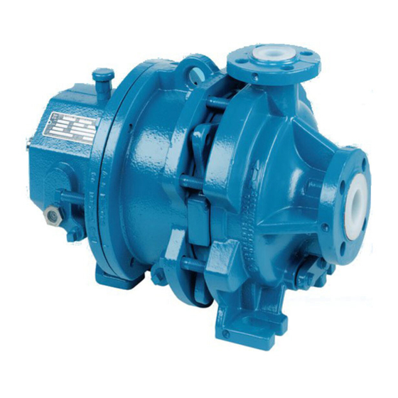
Goulds Model 3299 Plastic Lined Magnetic Drive pumps are frame mounted, volute type centrifugal pumps which are separately coupled to a driver such as an induction motor. Goulds Model 3299 Plastic Lined Magnetic Drive pumps are also available close coupled to a C-face motor; there is no separate pump bearing frame. -
Page 13: Pump Identification (Nameplate)
Bearing Manufacturer's Numerical Designation for Inboard and Outboard Anti-friction Bearings. NOTICE: There are five (5) basic drive frames available on the 3299. Drive frame designations are: A, B, C, D, E. Refer to Appendix A Engineering Information for torque ratings of these drives. Drive capability varies inversely with pumping temperature. - Page 14 CAUTION: When shipping bare magnet assemblies, especially by air, special precautions may be neces- sary. Usually the shipment of an assembled pump is not a problem. It is advisable to consult with the freight company. Model 3299 Installation Operation Maintenance...
-
Page 15: Safety Information
• When shipping bare magnet assemblies, especially by air, special precautions may be necessary. Usually the shipment of an assembled pump is not a problem. It is advisable to consult with the freight company. Model 3299 Installation Operation Maintenance... -
Page 16: Installation
Plastics are subject to cold flow, i.e., plastic parts may deform even when they are not in use. It is recommended to consult with Goulds Pumps if the pumps have been stored for a long period. Storage longer than one month is considered long term storage. Refer to Bulletin 52-130-373 in your submittal package or request a copy from your nearest Goulds Pumps Representative. -
Page 17: Foundation
(6) times the bolt diameter long and at least two (2) bolt sizes larger in I.D. If a nut and washer are used for locking, the washer should have an O.D. two (2) sizes larger than the sleeve. Model 3299 Installation Operation Maintenance... -
Page 18: Setting Baseplate
Do not exceed six (6) shims, using as thick a shim as possible, otherwise, sponginess or soft foot will result For 3299 frame mounted pumps, level and plumb the pump shaft, coupling faces and flanges by adding or removing shims between the blocks and bottom of the base. Hand tighten the anchor bolt nuts at first being very careful not to distort the base, snug down the nuts with a wrench. - Page 19 5.5 Setting baseplate For 3299 close coupled pumps, level and plumb the pump flanges, with the motor foot bolts loosened, by adding or removing shims between the blocks and bottom of the base. Hand tighten the anchor bolt nuts at first. Being careful not to distort the base, snug down the nuts with a wrench. Recheck that the pump flanges have remained level and plumb.
- Page 20 Figure 6: Single element coupling Figure 7: Alternate alignment method After the grout has thoroughly hardened (approximately 24 hours) tighten the foundation bolts fully. Check the alignment after the foundation bolts are tightened. Model 3299 Installation Operation Maintenance...
-
Page 21: Alignment Procedure
For angular alignment, change the indicator so it bears against the face of the same coupling half and proceed similarly to above. See Figure 6: Single element coupling on page 18Figure IVa and Figure 7: Alternate alignment method on page Model 3299 Installation Operation Maintenance... -
Page 22: Doweling
Suction and discharge piping should be anchored, supported and restrained near the pump to avoid im- posing forces and moments to the pump in excess of those advised as allowable by Goulds Pumps, Inc. Consult your submittal package for allowable nozzle loads on the 3299 or request this information from your nearest Goulds Pumps Representative. - Page 23 5.8 Suction and discharge piping Figure 8: Suction piping design When installing the pump piping, be sure to observe the following precautions: Model 3299 Installation Operation Maintenance...
- Page 24 5.8 Suction and discharge piping The 3299 pump has a thick plastic lining. If connecting pipes or valves have uneven sealing surfaces, damage may occur. It is recommended that lined steel insert gaskets be used. These are available from Goulds Pumps.
-
Page 25: Dry Run Warning
5.9 Dry run warning The 3299 must not be allowed to run dry and must be filled with liquid prior to start-up. Refer to 6.2 Pri- ming on page 27 for further details. -
Page 26: Condition Monitoring And Instrumentation
5.10 Condition monitoring and instrumentation The 3299 will provide long trouble free operation when correctly applied and can be supplied with key protective devices to guard against misoperation and damage to the unit. Many sealless pump failures are directly attributed to some degree of dry running. -
Page 27: Solids In Suspension
A 1/4 NPT leakage detector connection is provided as standard in the pump bracket which can be moni- tored for leakage past both containment shells with conductivity or capacitance probes. Other optional instrumentation connections available on the 3299 are: •... - Page 28 WARNING: Misapplication of this equipment may result in property damage, severe personal injury, or death. Always contact your nearest Goulds Pumps Representative when changing service con- ditions. Refer to Appendix "A" for data regarding operating limits. Model 3299 Installation Operation Maintenance...
-
Page 29: Operation
Assure that coupling is properly lubricated, if required. 10. For frame mounted units check rotation with coupling disconnected. On 3299 close coupled units, jog the pump and motor momentarily, about a half second, so that the motor rotation can be con- firmed by observing the motor fan direction. -
Page 30: Parallel Or Series Operation
The pump should not be started sooner than five (5) minutes after opening the suction and pressure sided valves. Venting of the containment shell can be improved by rotating the pump shaft several times by hand. Prime the pump. Model 3299 Installation Operation Maintenance... -
Page 31: Minimum Flow
Refer to your local Goulds Pumps Representative on appropriate minimum flow for your specific ma- chines. If it is necessary to operate a pump at flows below those specified by Goulds Pumps as minimum, then a by-pass line should be installed from the pump discharge to the suction source. The by-pass line should be sized so that the system flow plus the continuous by-pass flow is equal to or larger than the specified minimum flow. -
Page 32: Shutdown
A typical performance curve for a specific pump can be obtained from a Goulds Pumps Sales Represen- tative. This can be used in conjunction with a field test, if one is required. All Goulds Pumps tests and curves are based on the Hydraulic Institute Sealless Pump Standards. Any field test must be conducted according to these Standards. -
Page 33: Maintenance
7.3 Lubrication Bearings Bearing lubrication on 3299 pumps can be provided in either greased for life, oil bath, or oil mist arrange- ments. Check the pump nameplate for the specific type of lubrication provided. Bearing lubrication - greased for life... - Page 34 8000 hour year. Check the oil frequently for moisture, dirt, or signs of breakdown, especially during the first 1000 hours. NOTICE: Do not over oil; this causes the bearings to run hot. Model 3299 Installation Operation Maintenance...
-
Page 35: Maintenance Timetable
Bearing lubrication - oil mist Oil mist lubrication on 3299 pumps is optional. After the pump has been installed, flush the frame to re- move dirt, grit, and other impurities that may have entered the bearing housing during shipment or erec- tion. -
Page 36: Operating Problems
7.3 Lubrication on page 31 for recommended frequency of lubrication changes. The 3299 has been designed for long trouble free operation with proper application.. Since operating conditions vary widely, actual user experience will also vary. It is, there- fore, recommended that careful attention be given to notable deviations in baseline measurements before scheduling maintenance. - Page 37 27. Excessive impeller front hub Replace impeller. radial clearance. 28. Wrong direction of rotation. See item 6. Model 3299 Installation Operation Maintenance...
- Page 38 Failure to do this could result in damage to internal parts. Failure to follow all instructions could result in property dam- age, severe personal injury, or death. Model 3299 Installation Operation Maintenance...
- Page 39 For example, a vibrating steel plate can be felt as a vibration, and heard as noise. Eliminating or reducing the vibration has the same effect on the noise associated with it. For expert field service assistance contact your nearest Goulds Pumps Representative. Model 3299 Installation Operation Maintenance...
-
Page 40: Servicing
Drive assembly removal The 3299 has been designed with double back pullout capability without the need to disturb the casing, main piping, or driver. When repair work is only necessary on the antifriction bearings the bearing frame/outer magnet assembly can be sep- arated from the liquid end by removing capscrews (5-904-1) which hold the bearing frame to the bracket. - Page 41 Remove capscrews (1-904-1) which secure the bracket (5-193-0) to the bearing carrier (1-850-0). Next remove the bracket and inner (1-843-3) and outer (1-843-4) containment shells from their mountings on the bearing carrier. The inner and outer containment shells can be removed from Model 3299 Installation Operation Maintenance...
-
Page 42: Parts Inspection
.060". NOTICE: The sleeve journal bearings and bearing bushings are furnished as matched sets. When re- placing bearing always replace both rotating and stationary bearings. Model 3299 Installation Operation Maintenance... -
Page 43: Assembly
8.4 Assembly Follow all installation precautions covered in this manual. Always ensure that components are scrupulously clean before assembly. The inner and outer magnet carriers are magnetic and will pick up any ferrous debris. Model 3299 Installation Operation Maintenance... - Page 44 (1- 917-0) and socket head capscrew (1-904- 2). On Group II units install rear foot support (1-248-0) and secure to the bearing frame with two (2) capscrews (1-904-3). Model 3299 Installation Operation Maintenance...
- Page 45 Tighten the shaft assembly by applying a strap wrench around the OD of the impeller while wrapping another strap wrench around the inner magnet rotor assembly. Tighten to 75 ft-lb. torque. This torque can adequately be transmitted via strap wrenches. Model 3299 Installation Operation Maintenance...
- Page 46 Once the assembly is complete turn the pump shaft by hand and check for any binding or rubs. Any such condition must be corrected before the pump is operated. Plug all remaining external NPT connections on the pump. Model 3299 Installation Operation Maintenance...
-
Page 47: General Data
Table 7: Containment Shell Data - Thickness and Pressure Data Inner Shell Outer Shell Group Shell, in. End, in. Material Shell, in. End, in. Material Max Working Hydro Test Press., Psig Press., Psig 0.12 0.16 PTFE CFRP 0.12 0.16 PTFE CFRP Model 3299 Installation Operation Maintenance... -
Page 48: Casing And Impeller Design Data
.080- .09 8.07 2x3-6 0.30 0.012 7.07 4.54 .080- .09 13.24 1x1.5-8 0.21 0.012 3.42 9.39 .080- .09 43.66 1.5x3-8 0.40 0.012 7.59 4.23 .080- .09 45.07 1x2-10 10.0 0.30 0.012 4.29 7.48 .080- .09 96.94 Model 3299 Installation Operation Maintenance... - Page 49 A.2 Casing and impeller design data Maximum working pressure limits class 150 lb flanges Model 3299 Installation Operation Maintenance...
-
Page 50: Auxiliary And Instrumentation Connections
* opt * ANSI ISO RF flange (not shown) - orientation as specified Figure 10: Optional external flushing arrangement Instrumentation specifications • Power Sensor • Load Sentinel or Equal, Model 2200-40 (Dual Setpoint) 60Hz Operation Model 3299 Installation Operation Maintenance... -
Page 51: Pump Weights
Table 13: Close Coupled Less Motor lbs. Drive 8 Drive A Drive A Drive 8 Drive 8 Drive C Drive C Size 143/145 TC 182/184 TC 213/215 TC 254TC 254/256TC 284TSC 182/184 TC 1 x1.5-6 2x3-6 1 x1.5-8 Model 3299 Installation Operation Maintenance... - Page 52 A.4 Pump weights Table 14: Close Coupled Less Motor LBS. Drive E Drive E Drive D Drive D Drive D Drive D 284 Size 182/184 TC 213/215 TC 254/256 TC 284/286TSC 324/326TSC 1.5x3-8 1x2-10 Model 3299 Installation Operation Maintenance...
-
Page 53: Interchangeability
A.5 Interchangeability A.5 Interchangeability Group I Model 3299 frame mounted interchangeability Model 3299 Installation Operation Maintenance... - Page 54 A.5 Interchangeability Group I Model 3299 close coupled interchangeability Model 3299 Installation Operation Maintenance...
-
Page 55: Special Tools
It is also recommended that a nonmagnetic work bench be used. Typical manu- facturers of nonmagnetic tools are: Snap-On Tools Corp., Kenosha, WI Ampco Metal, Inc., Milwaukee, WI NSK Metals Inc., Athens, IN WARNING: Failure to follow these instructions could cause personal injury or equipment damage. Model 3299 Installation Operation Maintenance... -
Page 56: Recommended Spare Parts List And Parts Ordering Instructions
Bushing, Bearing-Outboard 1-843-3 Containment Shell, Inner 4-005-0 Impeller/Shaft, Integral Category Ill Quantity Catalog Number Part Name 1-842-3 Magnet Rotor Assembly, Inner 1-842-4 Magnet Rotor Assembly, Outer 1-843-4 Containment Shell, Outer 1-850-0 Carrier, Bearing 2-001-0 Casing Model 3299 Installation Operation Maintenance... - Page 57 Cover, Drain (Casing) 5-007-4 Shaft, Outer 5-282-0 Shaft, Stub Instructions for ordering parts When ordering parts for 3299 Pumps, be sure to furnish the following information to Goalds Pumps stocking distribu tor in your area: • Serial Number • Pump Size •...
-
Page 58: Impeller Trimming
Appendix D D.1 Impeller trimming When reducing the impeller diameter of 3299 integral impeller/shafts do not chuck directly on the plastic coated surfaces. Impeller trim sleeves are available from Goulds Pumps which will prevent damage to the shaft by the lathe jaws. For impeller trimming use a cobalt steel tool (not carbide tipped) and adjust the lathe speed to 500-600 rpm, slowly begin to take cuts using a forward feed of 0.010 inches across... -
Page 59: Returning Parts
Certain OSHA Hazard Communication Standard requirements must be followed when returning the pump/part as noted below. Reference is made to the Goulds Pumps Hazard Identification Label shown on page 39. Non-hazardous material If the material that the pump/part has been pumping is non-hazardous, check off the non-hazard- ous box on the Hazard Identification Label. - Page 60 E.1 Returning parts Figure 11: Return Material Form Model 3299 Installation Operation Maintenance...
-
Page 61: Assembly Section Group I, Frame Mounted
Appendix F Appendix F F.1 Assembly Section Group I, Frame Mounted Frame mounted 52-462-000 Model 3299 Installation Operation Maintenance... - Page 62 2-904-1 HH Cap Screw (Casing) 5-913-1 Gasket, Bracket 2-913-2 Gasket, Drain Cover 5-913-2 Gasket, Bearing Cover 4-005-0 Impeller/Shaft, Integral 5-921-0 Washer, Spring 5-007-4 Shaft, Outer 5-949·1 Sight Gauge (With Oil Lube Only) 5-018·4 Cover, Bearing Model 3299 Installation Operation Maintenance...
- Page 63 F.1 Assembly Section Group I, Frame Mounted Close coupled 182TC - 284TSC Model 3299 Installation Operation Maintenance...
- Page 64 SH Cap Screw (Outer Carrier to 5-910-3 Pipe Plug, Vapor/Leak Detector Shaft) 1-913-0 Spacer, Bracket 5-910-6 Pipe Plug, Decontamination 1-914-0 0-Ring, Inner Shaft 5-910-7 Pipe Plug, Adapter 1-917-0 Lockwasher, Internal Tooth 5-913-1 Gasket, Bracket 2-001-0 Casing 7-242-0 Motor, C-Face Model 3299 Installation Operation Maintenance...
- Page 65 F.1 Assembly Section Group I, Frame Mounted Close coupled 182TC- 326TSC Model 3299 Installation Operation Maintenance...
- Page 66 SH Cap Screw (Outer Carrier to Shaft) 5-910-3 Pipe Plug, Vapor/Leak Detector 1-913-0 Spacer, Bracket 5-910-6 Pip Plug, Decontamination 1-914-0 0-Ring, ln er Shaft 5-910-7 Pipe Plug, Adapter 1-917-0 Lockwasher, Internal Tooth 5-913-1 Gasket, Bracket 2-001-0 Casing 7-242-0 Motor, C-Face Model 3299 Installation Operation Maintenance...
- Page 67 F.1 Assembly Section Group I, Frame Mounted External flush arrangement Model 3299 Installation Operation Maintenance...
- Page 68 Visit our website for the latest version of this document and more information: www.gouldspumps.com ITT - Goulds Pumps Vertical Products Operation 240 Fall Street Seneca Falls, NY 13148 Form IOM.3299.en-US.2021-05 ©2021 ITT Corporation The original instruction is in English. All non-English instructions are translations of the original instruction.
Need help?
Do you have a question about the 3299 and is the answer not in the manual?
Questions and answers