Chapters
Table of Contents

Subscribe to Our Youtube Channel
Related Manuals for Ecolab EcoTrans II pH


Summary of Contents for Ecolab EcoTrans II pH
- Page 1 Betriebsanleitung Operating instructions Manuel d’utilisation EcoTrans II pH Mess- und Regelgerät pH 0-14 FRANÇAIS DEUTSCH ENGLISH EcoTrans II pH MAN052993 Rev. 2-01.2024 24.01.2024...
-
Page 2: Table Of Contents
Inhaltsverzeichnis Inhaltsverzeichnis Allgemeines ......................4 1.1 Hinweise zur Betriebsanleitung ................ 4 1.2 Gewährleistung ....................8 1.3 Transport ......................8 1.4 Verpackung ....................... 9 1.5 Lagerung ......................10 1.6 Kontakt ......................10 Sicherheit ......................11 2.1 Allgemeine Sicherheitshinweise ..............11 2.2 Bestimmungsgemäße Verwendung ..............11 2.3 Sicherheitsmaßnahmen durch den Betreiber .......... - Page 3 Inhaltsverzeichnis EG-Konformitätserklärung .................. 54 Index........................55 MAN052993 Rev 2-01.2024...
-
Page 4: Allgemeines
Verfügung gestellt. Zum Öffnen und Anzeigen der Anleitungen empfehlen wir den PDF Viewer ( https://acrobat.adobe.com ). Anleitungen über den Internetauftritt der Ecolab Engineering GmbH abrufen Über den Internetauftritt des Herstellers ( https://www.ecolab-engineering.de ) kann unter dem Menüpunkt [Mediacenter] / [Bedienungsanleitungen] die gewünschte Anleitung gesucht und ausgewählt werden. - Page 5 über den "Google Play Store" installiert werden. Rufen sie den "Google Play Store" mit Ihrem Smartphone /Tablet auf. Geben Sie den Namen „Ecolab DocuAPP“ im Suchfeld ein. Wählen Sie die Ecolab DocuAPP aus. Betätigen Sie den Button [installieren]. ð Die „DocuApp“...
- Page 6 Allgemeines Artikelnummern / EBS-Artikelnummern Innerhalb dieser Betriebsanleitung können sowohl Artikelnummern, als auch EBS-Artikelnummern dargestellt sein. EBS-Artikelnummern sind Ecolab interne Nummern und werden „konzernintern“ verwendet. Symbole, Hervorhebungen und Aufzählungen Sicherheitshinweise sind in dieser Anleitung durch Symbole gekennzeichnet und werden durch Signalworte eingeleitet, die das Ausmaß der Gefährdung zum Ausdruck bringen.
- Page 7 Die Überlassung dieser Anleitung an Dritte, Vervielfältigungen in jeglicher Art und Form, auch auszugsweise, sowie die Verwertung und/oder Mitteilung des Inhaltes sind ohne schriftliche Genehmigung von Ecolab (im folgenden "Hersteller" genannt) außer für interne Zwecke nicht gestattet. Zuwiderhandlungen verpflichten zu Schadenersatz.
-
Page 8: Gewährleistung
Hersteller nur unter folgenden Bedingungen übernommen: Montage, Anschluss, Einstellung, Wartung und Reparaturen werden von autorisiertem Fachpersonal durchgeführt. EcoTrans II pH wird entsprechend den Ausführungen dieser Bedienungsanleitung verwendet. Bei Reparaturen werden nur Original-Ersatzteile verwendet. Nur die zugelassenen Ecolab Produkte werden verwendet. -
Page 9: Verpackung
Allgemeines GEFAHR! Gefahr durch Inbetriebnahme eines durch den Transport beschädigten Gerätes. Wird beim Auspacken ein Transportschaden festgestellt, darf keine Installation oder Inbetriebnahme durchgeführt werden. Durch Installation / Inbetriebnahme eines beschädigten Gerätes, können unkontrollierbare Fehler auftreten, die durch den Einsatz von aggressiven Dosiermitteln zu irreparablen Schäden am Personal und/oder des Gerätes führen können. -
Page 10: Lagerung
Bei Lagerung von länger als 3 Monaten regelmäßig den allgemeinen Zustand aller Teile und der Verpackung kontrollieren. Falls erforderlich, die Konservierung auffrischen oder erneuern. Kontakt Hersteller Ecolab Engineering GmbH Raiffeisenstraße 7 D-83313 Siegsdorf Bevor sie den Hersteller kontaktieren empfehlen wir immer zuerst den Kontakt Telefon (+49) 86 62 / 61 0 zu Ihrem Vertriebspartner herzustellen. -
Page 11: Sicherheit
– Das Gerät darf nur mit der in den Technischen Daten angegebenen Versorgungs- und Steuerspannung betrieben werden. Bestimmungsgemäße Verwendung Das EcoTrans II pH dient ausschließlich zur Bestimmung und Regelung des pH-Werts in validierten Chemikalien. Die Nutzung ist auf gewerbliche Anwendungen im industriellen Umfeld beschränkt; eine private Nutzung ist ausgeschlossen. -
Page 12: Sicherheitsmaßnahmen Durch Den Betreiber
Sicherheit Sicherheitsmaßnahmen durch den Betreiber HINWEIS! Es wird darauf hingewiesen, dass der Betreiber sein Bedien- und Wartungspersonal bezüglich der Einhaltung aller notwendigen Sicherheitsmaßnahmen zu schulen, einzuweisen und zu überwachen hat. Die Häufigkeit von Inspektionen und Kontrollmaßnahmen muss eingehalten und dokumentiert werden! WARNUNG! Gefahr durch unsachgemäß... -
Page 13: Personalanforderungen
Sicherheit die Beleuchtung der Arbeitsplätze ist betreiberseitig laut DIN EN 12464-1 (im Geltungsbereich der Bundesrepublik Deutschland) herzustellen. Beachten Sie die bei Ihnen gültigen Vorschriften! sicherzustellen, dass bei der Montage und Inbetriebnahme, wenn diese vom Betreiber selbst durchgeführt werden, örtliche Vorschriften beachtet werden. Personalanforderungen Qualifikationen GEFAHR! -
Page 14: Persönliche Schutzausrüstung (Psa)
Sicherheit GEFAHR! Hilfspersonal ohne besondere Qualifikation Hilfspersonal ohne besondere Qualifikation, bzw. ohne gesonderte Ausbildung, welche die hier beschriebenen Anforderungen nicht erfüllen, kennen die Gefahren im Arbeitsbereich nicht. Daher besteht für Hilfspersonal die Gefahr von Verletzungen. Hilfspersonal ohne Fachkenntnisse müssen unbedingt mit dem Umgang der Persönlichen Schutzausrüstung (PSA) für die zu verrichtenden Tätigkeiten vertraut gemacht werden, bzw. - Page 15 Sicherheit Rutschgefahr GEFAHR! Rutschgefahren sind mit nebenstehendem Symbol gekennzeichnet. Verschüttete Chemikalien erzeugen bei Nässe Rutschgefahr. WARNUNG! Rutschgefahr durch austretende Flüssigkeit im Arbeits- und Bereitstellungsbereich! – Bei Arbeiten rutschfeste, chemieresistente Schuhe tragen. – Produktbehälter in eine Wanne stellen um eine Rutschgefahr durch austretende Flüssigkeiten zu vermeiden.
-
Page 16: Umweltschutzmaßnahmen
Sicherheit UMWELT! Ausgelaufene, verschüttete Chemikalien können die Umwelt schädigen. Ausgelaufene, verschüttete Chemikalie nach Anweisungen des Sicherheitsdatenblattes fachgerecht aufnehmen und entsorgen. Unbedingt auf die Verwendung der vorgeschrieben PSA achten. Vorbeugende Maßnahme: – Produktbehälter in eine Wanne stellen, um ausgetretene Flüssigkeiten umweltgerecht aufzufangen. Umweltschutzmaßnahmen UMWELT! Das Umweltzeichen kennzeichnet Maßnahmen des Umweltschutzes. - Page 17 Sicherheit GEFAHR! Durch unfachmännisch durchgeführte Installations-, Wartungs- oder Reparaturarbeiten können Schäden und Verletzungen auftreten. Alle Installations-, Wartungs- und Reparaturarbeiten dürfen nur von autorisiertem und geschultem Fachpersonal nach den geltenden örtlichen Vorschriften ausgeführt werden. Sicherheitsbestimmungen und vorgeschriebene Schutzkleidung im Umgang mit Chemikalien sind zu beachten.
-
Page 18: Lieferumfang
Lieferumfang Lieferumfang Abbildung Bezeichnung Art.-Nr. EcoTrans II Mess- und Regelgerät pH 0-14 422000018 Bedienungsanleitung EcoTrans II pH Hinweis: Die Betriebsanleitung wird zum Download zur MAN052993 Verfügung gestellt. Ä „Verfügbare Anleitungen“ auf Seite 4 MAN052993 Rev 2-01.2024... -
Page 19: Funktionsbeschreibung
Funktionsbeschreibung Funktionsbeschreibung Das EcoTrans II pH kann wahlweise als Regelgerät oder als Messumformer genutzt werden. Regelausgang Diese Funktionsart umfasst einen regelbaren Stromausgang mit einstellbarem PI- Regelverhalten (stetiger Regler). Das Display zeigt hier neben dem aktuellen Messwert die aktuelle Regelgröße am Stromausgang in % und die eingestellte Regelrichtung. -
Page 20: Aufbau
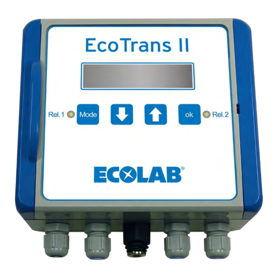
Aufbau Aufbau Display Taste "Runter" Taste "Hoch" Taste "Mode" LED "Relais 1" Taste "OK" LED "Relais 2" Kabeldurchführung für Netzkabel / Netzanschluss Kabeldurchführung für Relais-Ausgang Anschluss pH-Sensor Kabeldurchführung für Regelstromausgang Kabeldurchführung für Freigabeeingang Abb. 1: Aufbau Gerätefront Deckelverriegelung Deckel Sicherung 2,5 A Klemmleiste K1 - K11 Klemmleiste K12 - K19 Klemmleiste K20 - K25... -
Page 21: Montage Und Installation
Montage und Installation Montage und Installation Personal: Elektrofachkraft Servicepersonal Schutzausrüstung: Schutzhandschuhe Schutzbrille Sicherheitsschuhe HINWEIS! Sachschäden durch Verwendung von falschem Werkzeug! Durch Verwendung von falschem Werkzeug können Sachschäden entstehen. Nur bestimmungsgemäßes Werkzeug verwenden. GEFAHR! Durch unfachmännisch durchgeführte Installations-, Wartungs- oder Reparaturarbeiten können Schäden und Verletzungen auftreten. –... -
Page 22: Montage
Montage und Installation GEFAHR! Lebensgefahr durch elektrischen Strom! Gefahren durch elektrischen Strom sind mit nebenstehendem Symbol gekennzeichnet. Arbeiten an solchen Stellen dürfen ausschließlich durch ausgebildetes und autorisiertes Fachpersonal durchgeführt werden. Bei Berührung mit spannungsführenden Teilen besteht unmittelbare Lebensgefahr durch Stromschlag. Beschädigung der Isolation oder einzelner Bauteile kann lebensgefährlich sein. - Page 23 Montage und Installation Abb. 3: Bohrplan Montageort des EcoTrans II pH wählen und Bohrlöcher gem. Bohrplan Abb. 3 anzeichnen. Befestigungsbohrungen bohren und Dübel Æ 6 mm setzen. Deckelverriegelung Deckel Befestigungsbohrung Abb. 4: Gerät montieren Deckelverriegelung lösen und Deckel öffnen. Gerät mit Dübelschrauben Æ 4 mm befestigen.
-
Page 24: Elektrische Installation
Montage und Installation Elektrische Installation Allgemeine Hinweise HINWEIS! Gefahr von Fehlmessungen und Fehlermeldungen Das Messverfahren ist anfällig gegen elektromagnetische Felder und Einflüsse. Diese können zu Fehlmessungen und Fehlermeldungen führen: – Das Gerät, die Messzelle, die Messzellenleitung und die Signalleitung nicht in der Nähe frequenzgesteuerten Motoren, Mobilfunkantennen oder WLAN- Antennen montieren. - Page 25 – Wird die Verbindung zwischen den Klemmen K18 und K19 getrennt, ist die Freigabe deaktiviert. Im Display wird angezeigt. Die Relaisausgänge und der Normsignalausgang sind gesperrt. Messkabel pH-Messkabel am Anschluss pH-Sensor ( Abb. 1 , ) anschließen. ð Das EcoTrans II pH ist betriebsbereit. MAN052993 Rev 2-01.2024...
-
Page 26: Inbetriebnahme
Inbetriebnahme Inbetriebnahme Personal: Servicepersonal Fachkraft Schutzausrüstung: Schutzbrille Schutzhandschuhe, chemikalienbeständig Erstinbetriebnahme Voraussetzungen: Gerät ist montiert und vollständig angeschlossen Stromversorgung einschalten. Funktionsart einstellen. Ä Kapitel 8.8.1 „Funktionsart (Strom Modus) einstellen“ auf Seite 42 Ä Kapitel 8.8 „Konfiguration“ Weitere Mess- und Regelparameter einstellen. auf Seite 40 Ä... -
Page 27: Bedienung
Bedienung Bedienung Tastenfunktionen Taste "Mode" Taste "Runter" Taste "Hoch" Taste "OK" Abb. 6: Tastenfeld Anwählen des Einstellmodus Rückkehr aus einer Einstellebene in den Einstellmodus Rückkehr in den Betriebsmodus Auswählen der Einstellebene Auswählen von Einstellwerten Übernahme der gewählten Einstellebene Bestätigen des ausgewählten Werts (die Einstellbarkeit eines Werts wird durch das Zeichen * rechts in der oberen Displayzeile dargestellt) Sobald Taste "Mode"... -
Page 28: Menüstruktur
Bedienung Anzeige bei Funktionsart „Messumformer“ Messwert Normsignal Freigabesignal aktiv Abb. 7: Anzeige bei Funktionsart „Messumformer“ In der Funktionsart „Messumformer“ erfasst das Gerät Messwerte im Bereich 0 - 14 pH und wandelt diese in ein Normsignal 0 -20 mA bzw. 4 - 20 mA um. In der Anzeige werden der aktuelle Messwert und der dazugehörige Normsignalwert dargestellt. - Page 29 Bedienung Menüstruktur bei Funktionsart „Messumformer“ In der Funktionsart „Messumformer“ erfasst das Gerät Messwerte im Bereich 0 - 14 pH und wandelt diese in ein Normsignal 0 -20 mA bzw. 4 - 20 mA um. Ä Kapitel 8.4 „Kalibrierung durchführen“ auf Seite 31 Ä...
- Page 30 Bedienung Menüstruktur bei Funktionsart „Regelausgang“ In der Funktionsart „Regelausgang“ wird der Normsignalausgang als Regelausgang mit einstellbarem PI Regelverhalten betrieben. Ä Kapitel 8.4 „Kalibrierung durchführen“ auf Seite 31 Ä Kapitel 8.5 „Regler stoppen“ auf Seite 34 Ä Kapitel 8.6 „Regelparameter einstellen (nur bei Funktionart „Regelausgang“...
-
Page 31: Kalibrierung Durchführen
Kalibriere… <OK> drücken Abb. 10: Übersicht Menü „KALIBRIEREN“ Bei der Kalibrierung wird mit dem EcoTrans II pH der pH-Wert von zwei bekannten Kalibrierlösungen (Puffer) ermittelt. Die ermittelten Messwerte werden dann auf den Wert der jeweils verwendeten Pufferlösung justiert. Um genaue Messungen zu erreichen, ist eine regelmäßige Kalibrierung des Geräts, mindestens alle 12 Wochen, erforderlich. - Page 32 Bedienung Im nachfolgenden Beispiel wird das EcoTrans II pH für die Messung säurehaltiger Produkte kalibriert. Material: Spezialreiniger für pH- und RH-Messketten (418853128) 20 ml Pufferlösung pH 7,00 (418853126) 20 ml Pufferlösung pH 4,01 (418853125) Voraussetzungen: Gerät ist montiert und vollständig angeschlossen Messfühler vorbereiten...
- Page 33 Bedienung ð Im Display wird „Zweiter Puffer <OK> drücken“ angezeigt. 11. Messfühler 5 Sekunden lang in reines Wasser (H O) stellen. 12. Messfühler mit einem fusselfreiem Tuch reinigen. Zweite Messung (Puffer2 ) durchführen 13. Messfühler in die Pufferlösung pH 4,01 eintauchen. drücken.
-
Page 34: Regler Stoppen
Bedienung Regler stoppen KALIBRIEREN STOPPEN Abb. 11: Übersicht "Regler stoppen" Sobald am EcoTrans II die Taste "Mode" gedrückt wird, werden die Relaisausgänge und der Regelstromausgang abgeschaltet. Wird zwei Minuten lang keine Taste betätigt, wird der Betriebsmodus automatisch wieder aktiviert und die Relaisausgänge und der Regelstromausgang eingeschaltet. - Page 35 Bedienung Zum Starten des Reglers im Einstellmenü „STARTEN“ auswählen und drücken. MAN052993 Rev 2-01.2024...
-
Page 36: Regelparameter Einstellen (Nur Bei Funktionart „Regelausgang" )
Bedienung Regelparameter einstellen (nur bei Funktionart „Regelausgang“ ) KALIBRIEREN STOPPEN Sollwert Nachstellzeit P-Bereich REGELPARAMETER (senken) Relais 1 wenn Hysterese Relais 2 wenn Messw. Messw. Abb. 13: Übersicht Menü „REGELPARAMETER“ Unter Menüpukt „REGELPARAMETER“ können Sollwert, Regelrichtung und PI- Regelverhalten für den Regelstromausgang eingestellt werden. Außerdem sind hier Wirksinn, Schaltpunkte und Hysterese für die beiden Relaisausgänge auswählbar. - Page 37 Bedienung drücken. P-Bereich (senken) Abb. 16: Display „P-Bereich“ drücken, Wert für das Proportionalverhalten des PI Reglers (P-Bereich) und die Regelrichtung (heben / senken) einstellen via und mit bestätigen. Der P-Anteil sorgt für eine schnelle Annäherung an den Sollwert. drücken. Nachstellzeit Abb.
- Page 38 Bedienung Relais 2 wenn Messw. Abb. 20: Display „Schaltpunkt Relais 2“ drücken, Wirksinn (</>) und Schaltpunkt für Relais 2 einstellen via und mit bestätigen. ð Die Regelparameter sind eingestellt. ð Wenn ein Relais aktiviert ist leuchtet die zugehörige LED. Die Schalthysterese wirkt gegen den eingestellten Wirksinn des Relaisausgangs.
-
Page 39: Relais Konfigurieren (Nur Bei Funktionsart „Messumformer" )
Bedienung Relais konfigurieren (nur bei Funktionsart „Messumformer“ ) KALIBRIEREN STOPPEN Hysterese Relais 2 wenn Relais 1 wenn RELAIS-KONFIG. Messw. Messw. Abb. 21: Übersicht Menü „RELAIS-KONFIG.“ Unter Menüpunkt „RELAIS-KONFIG.“ können Wirksinn, Schaltpunkte und Hysterese für die beiden Relaisausgänge eingestellt werden. Voraussetzungen: Gerät ist montiert und vollständig angeschlossen Kalibrierung durchgeführt Gerät ist als „Messumformer“... -
Page 40: Konfiguration
Bedienung ð Im Display erscheint „Hysterese“ und die aktuelle Einstellung, z.B. „2 %“ . drücken, Schalthysterese für beide Relais einstellen via und mit bestätigen. Die Schalthysterese wirkt gegen den eingestellten Wirksinn des Relaisausgangs. Einstellbeispiel Einstellung Wirksinn / Schaltpunkt Relais 1 - Relais 1 wenn Messw. < pH 7.00 Hysterese - 2 % Schaltverhalten... - Page 41 Bedienung Übersicht Menü „KONFIGURATION“ Ä Kapitel 8.8.1 „Funktionsart (Strom Modus) einstellen“ auf Seite 42 Ä Kapitel 8.8.2 „Stromausgang einstellen“ auf Seite 43 Ä Kapitel 8.8.3 „Messwertkorrektur einstellen“ KALIBRIEREN auf Seite 45 Ä Kapitel 8.8.4 „Sprache einstellen“ auf Seite 46 STOPPEN REGELPARAMETER Strom Modus KONFIGURATION...
-
Page 42: Funktionsart (Strom Modus) Einstellen
Bedienung 8.8.1 Funktionsart (Strom Modus) einstellen Strom Modus KONFIGURATION Regelausgang Abb. 24: Übersicht Menü „Funktionsart einstellen“ Das Gerät kann in folgenden Funktionsarten konfiguriert werden: Messumformer Anzeige von Messwert und Stromausgang (mA) Regelausgang Anzeige von Messwert und Regelstärke Voraussetzungen: Gerät ist montiert und vollständig angeschlossen Kalibrierung durchgeführt Spannungsversorgung einschalten. -
Page 43: Stromausgang Einstellen
Bedienung 8.8.2 Stromausgang einstellen Strom Modus KONFIGURATION Regelausgang Messumformer Stromausgang Abb. 28: Übersicht Menü „Stromausgang“ Das Gerät kann mit folgenden Stromsignal-Einstellungen als Einheitssignal betrieben werden: 0 mA ... 20 mA 4 mA ... 20 mA Voraussetzungen: Gerät ist montiert und vollständig angeschlossen Kalibrierung durchgeführt Spannungsversorgung einschalten. - Page 44 Bedienung pH Messwert für 0 bzw. 4 mA zuordnen (eingeben) via und mit bestätigen. Abb. 32: Messwertzuordnung 2 von 2 pH - Messwert für 20mA zuordnen (eingeben) via und mit bestätigen. Stromausgang Abb. 33: Stromausgang eingestellt (Beispiel 4...20mA) drücken bis das Grundbild erscheint. ð...
-
Page 45: Messwertkorrektur Einstellen
Bedienung 8.8.3 Messwertkorrektur einstellen Strom Modus KONFIGURATION Regelausgang Stromausgang Korrektur pH Abb. 34: Übersicht Menü „Messwertkorrektur“ Abhängig von Einbauort und -Lage des Messfühlers in einem Tank oder einem Rohr, kann es zu Messabweichungen kommen. Diese Messabweichungen können im Menü „Korrektur pH“ geräteabhängig korrigiert werden. Voraussetzungen: Gerät ist montiert und vollständig angeschlossen Kalibrierung durchgeführt... -
Page 46: Sprache Einstellen
Regelausgang Stromausgang Korrektur pH Sprache Deutsch Abb. 37: Übersicht Menü „Sprache“ Die Benutzeroberfläche des EcoTrans II pH kann folgende Sprachen darstellen: Deutsch Englisch Im Auslieferungszustand ist Sprache Deutsch voreingestellt. Nachfolgend ist die Einstellung der Sprache bei deutscher Voreinstellung beschrieben. Voraussetzungen: Gerät ist montiert und vollständig angeschlossen. - Page 47 Bedienung Abb. 40: Sprache einstellen English ð Die Sprache ist auf Englisch umgestellt. drücken bis das Grundbild erscheint. ð Relaisausgänge und Stromausgang sind eingeschaltet. MAN052993 Rev 2-01.2024...
-
Page 48: Wartung
Wartung Wartung Personal: Bediener Fachkraft Schutzausrüstung: Schutzbrille Schutzhandschuhe, chemikalienbeständig Wartungsintervalle Intervall Wartungsarbeit Personal Gerät reinigen Bediener Monatlich Fachkraft pH-Messelektrode auf Ablagerungen kontrollieren Vierteljährlich pH-Messelektrode reinigen Fachkraft Fachkraft pH-Messelektrode auf Ablagerungen kalibrieren. Ä Kapitel 8.4 „Kalibrierung durchführen“ auf Seite 31 Zur Reinigung der Messelektrode empfehlen wir folgende Reinigungslösung: Reiniger Ä... -
Page 49: Betriebsstörungen Und Fehlerbehebung
Betriebsstörungen und Fehlerbehebung Betriebsstörungen und Fehlerbehebung Fehlerbeschreibung Ursache Abhilfe Messzelle anschließen Anzeige zeigt „ELEKTRODENFEHLER“ Keine Messzelle angeschlossen Verbindungsleitung kontrollieren Verbindungsleitung Messzelle- und gegebenenfalls wechseln Messverstärker unterbrochen Elektrodenkabel im Bereich der Anzeige bleibt trotz verändertem pH-Wert Kurzschluss in der Elektrodenzuleitung Anschlüsse überprüfen, Stecker bei ca. -
Page 50: Zubehör
Zubehör Zubehör Darstellung Bezeichnung Art. Nr Anschlusskabel pH 2m 418439450 Anschlusskabel pH 5m 418439451 pH-Einstabmesskette PTFE, pH 1 - 418853008 12, bis 6 bar pH-Einstabmesskette Keramik, pH 418853011 1 - 12, bis 3 bar pH-Einstabmesskette Keramik, pH- 418853016 Bereich: 1 - 14, bis 3 bar Impedanzwandler 418853005 Schrägsitz-Durchflußarmatur PVC... - Page 51 Zubehör Darstellung Bezeichnung Art. Nr Pufferlösung pH 9,21 20 ml 418853127 Spezialreiniger für pH- und rH- 418853128 Messketten 250ml MAN052993 Rev 2-01.2024...
-
Page 52: Technische Daten
Technische Daten Technische Daten Allgemeine Daten Angabe Wert Einheit 142 x 125 x 60 mm Abmessungen (H x B x T) 0,6 kg Gewicht IP 65 Schutzart zweizeilig Anzeige chemisch resistentes Beständigkeit Kunststoffgehäuse (ABS) 110 - 230V, 50/60Hz Stromversorgung Leistungsaufnahme 2,5 A Sicherung SN6 Buchse für pH-... - Page 53 Technische Daten Produktkennzeichnung / Typenschild Abb. 41: Typenschild Gerätenummer Herstellungsjahr Gerätebezeichnung Data Matrix Code bestehend aus der Gerätenummer, gefolgt vom Anschlussspannung Produktionscode Produktionscode Hersteller bestehend aus "Produktionsauftrag / Link zur aktuellen Betriebsanleitung Produktionsdatum / fortlaufende Gerätenummer" MAN052993 Rev 2-01.2024...
- Page 54 EG-Konformitätserklärung EG-Konformitätserklärung MAN052993 Rev 2-01.2024...
- Page 55 Darstellungsweise ....7 Anleitungen über den Internetauftritt der Ecolab Engineering GmbH abrufen ..4 Erstinbetriebnahme ....26 Artikelnummern / EBS-Artikelnummern .
- Page 56 Index Installations-, Wartungs- oder Reparaturarbeiten Personalanforderung Hinweis: unfachmänische Durchführung Hilfspersonal ohne besondere ........17 Qualifikation .
- Page 57 Index Steuerungsbeschreibung Unsachgemäßer Transport ....8 Tastenfunktionen ....27 Urheberschutz Betriebsanleitung .
- Page 58 Table of contents Table of contents General ........................4 1.1 Notes on the operating instructions ..............4 1.2 Warranty ......................8 1.3 Transportation ....................8 1.4 Packaging ......................9 1.5 Storage ......................10 1.6 Contact ......................10 Safety ........................11 2.1 General safety advice ..................
- Page 59 Table of contents EC Declaration of Conformity ................54 Index........................55 MAN052993 Rev 2-01.2024...
-
Page 60: General
To open and display the operating instructions, we recommend that you use Adobe PDF Viewer( https://acrobat.adobe.com ). Accessing operating instructions using the website of Ecolab Engineering GmbH You can search for and select the required instructions on the manufacturer’s website ( https://www.ecolab-engineering.de ) under [Media Centre] / [Operating Instructions]. - Page 61 Accessing operating instructions using a smartphone/tablet You can use the Ecolab ‘DocuApp’ to access all operating manuals, catalogues, certificates and CE declarations of conformity published by Ecolab Engineering using a smartphone or tablet (Android & iOS ). The published documents are always up to date and new versions are displayed immediately.
- Page 62 General Symbols, highlights and bulleted lists Safety instructions in this manual are identified by symbols and introduced by signal words expressing the extent of the hazard. DANGER! Indicates an imminently hazardous situation which, if not avoided, could result in death or serious injury. WARNING! Indicates a potentially imminent danger that can lead to serious injuries or even death.
- Page 63 The transfer of this manual to third parties, reproductions in any kind and form, even in extracts, as well as the exploitation and/or communication of the content are not permitted without the written permission of Ecolab (hereinafter referred to as "manufacturer") except for internal purposes. Any violations result in obligatory compensation for damages.
-
Page 64: Warranty
Assembly, connection, set-up, maintenance and repair must be carried out by qualified and authorised specialists. EcoTrans II pH is used in accordance with the information provided in these operating instructions. Only OE spare parts are to be used for repairs. -
Page 65: Packaging
General DANGER! Risks when commissioning equipment which has been damaged during transportation. Installation or start-up must not take place if any transport damage is detected when unpacking the system. Installing/starting up a damaged pump may result in uncontrollable errors, which may lead to irreparable damage to personnel and/or of the equipment when using aggressive dosing agents. -
Page 66: Storage
For storage periods of more than 3 months, check the general condition of all parts and packaging regularly. If necessary, refresh or renew the preservative. Contact Manufacturer Ecolab Engineering GmbH Raiffeisenstraße 7 D-83313 Siegsdorf Before contacting the manufacturer, we always recommend contacting your Telephone (+49) 86 62 / 61 0 distributor first. -
Page 67: Safety
Technical Data section. Intended use The EcoTrans II pH is used only used to determine and control the pH value in validated chemicals. Use is restricted to commercial applications in an industrial environment; private use is excluded. -
Page 68: Safety Measures Taken By The Operator
Safety Safety measures taken by the operator NOTICE! It is expressly up to the operator to train, monitor and instruct its operating and maintenance personnel so that they comply with all of the necessary safety measures. The frequency of inspections and controls must be complied with and documented. -
Page 69: Personnel Requirements
Safety The operator must provide lighting in workplaces in accordance with DIN EN 12464-1 (within the Federal Republic of Germany). Observe the local applicable regulations! To ensure that local regulations are complied with during installation and commissioning, if these procedures are conducted by the operator Personnel requirements Qualifications DANGER! -
Page 70: Personal Protective Equipment (Ppe)
Safety DANGER! Auxiliary personnel without special qualifications Auxiliary personnel without special qualifications or without special training who do not meet the requirements described here are unaware of the dangers in the work area. Therefore, there is a risk of injury to auxiliary personnel. It is imperative that auxiliary personnel without specialist knowledge are familiarised with the use of personal protective equipment (PPE) for the activities to be performed, or are appropriately trained, and that these... - Page 71 Safety Risk of slipping DANGER! Risks of slipping are to be identified using the adjacent symbol. Spilled chemicals are a slipping hazard in wet conditions. WARNING! Risk of slipping due to fluid in the operation and provisioning area! – Wear non-slip, chemically resistant shoes when working. –...
-
Page 72: Environmental Protection Measures
Safety ENVIRONMENT! Leaking and spilled chemicals can harm the environment. Professionally record and discard leaking and spilled chemicals according to the instructions of the safety data sheet. Be sure to pay attention to the use of the prescribed PPE. Preventive action: –... - Page 73 Safety DANGER! Damage and injuries may occur if installation, maintenance or repair work is carried out incorrectly. All installation, maintenance and repair work must only be performed by authorised and trained specialist personnel in accordance with the applicable local regulations. Safety regulations and prescribed protective clothing when handling chemicals should be followed.
-
Page 74: Delivery
Delivery Delivery Figure Description Article no. EcoTrans II measuring and control device pH 0–14 422000018 Operating instructions EcoTrans II pH Note: The operating instructions are available to download. MAN052993 Ä ‘Available instructions’ on page 4 MAN052993 Rev 2-01.2024... -
Page 75: Function Description
Function description Function description This EcoTrans II pH can be used either as a control device or as a measuring transducer. Control output This function type comprises a controllable current output with adjustable PI control behaviour (continuous controller). In addition to the current measured value, the display shows the current control variable at the current output in % and the set control direction. -
Page 76: Structure
Structure Structure Display “Down” button “Up” button “Mode” button “Relay 1” LED “OK” button “Relay 2” LED Cable bushing for mains cable/mains power supply Cable bushing for relay output pH sensor connector Cable bushing for control current output Cable bushing for enable input Fig. -
Page 77: Assembly And Connection
Assembly and connection Assembly and connection Personnel: Qualified electrician Service personnel Protective equipment: Protective gloves Protective eyewear Safety shoes NOTICE! Material damage by using incorrect tools! Material damage may arise by using incorrect tools. Use the correct tools. DANGER! Damage and injuries may occur if installation, maintenance or repair work is carried out incorrectly. -
Page 78: Installation
Assembly and connection DANGER! Risk of fatal injury from electric current! Electrical hazards are identified by the symbol opposite. Work on those places may only be carried out by skilled personnel who are duly trained and authorised. Contact with live parts represents immediate danger to life due to electrocution. Damage to the insulation or individual components can be life-threatening. - Page 79 Assembly and connection Fig. 3: Drilling plan Select the mounting location of the EcoTrans II pH and drill holes in accordance with the drilling plan Fig. 3 . Drill the fixing holes and place the Æ 6 mm dowels. Cover lock...
-
Page 80: Electrical Installation
Assembly and connection Electrical installation General information NOTICE! Risk of incorrect measurements and error messages The measurement method is susceptible to electromagnetic fields and influences. These can lead to incorrect measurements and error messages: – Do not install the unit, measurement cell, measurement cell cable or signal line near frequency-controlled motors, mobile communication antennas, or wireless LAN antennas. - Page 81 The display shows The relay outputs and the standard signal output are blocked. Measuring cable Connect the pH measuring cable to the pH sensor connector ( Fig. 1 , ð The EcoTrans II pH is ready for operation. MAN052993 Rev 2-01.2024...
-
Page 82: Start-Up
Start-up Start-up Personnel: Service Personnel Qualified employee Protective equipment: Protective goggles Chemical resistant protective gloves Initial start-up Requirements: The unit is mounted and fully connected Switch on the power supply. Set the operating mode. Ä Chapter 8.8.1 ‘Setting the function type (Current mode)’ on page 42 Ä... -
Page 83: Operation
Operation Operation Key functions “Mode” button “Down” button “Up” button “OK” button Fig. 6: Keypad Select the setting mode Return from a setting level to setting mode Return to operating mode Select setting level Select setting values Apply the selected setting level Confirm the selected value (the ability to set a value is indicated by the character * on the right of the top line of the display) -
Page 84: Menu Structure
Operation Display for function type ‘Transducer’ Measured value Standard signal Enable signal active Fig. 7: Display for function type ‘Transducer’ In the function type ‘Transducer’ , the device records measured values in the range 0–14 pH and converts them into a standard signal of 0–20 mA or 4–20 mA. The display shows the current measured value and the corresponding standard signal value Display for function type ‘Control Output’... - Page 85 Operation Menu structure for function type ‘Transducer’ In the function type ‘Transducer’ , the device records measured values in the range 0–14 pH and converts them into a standard signal of 0–20 mA or 4–20 Ä Chapter 8.4 ‘Perform calibration’ on page 31 Ä...
- Page 86 Operation Menu structure for function type ‘Control Output’ In the function type ‘Control Output’ , the standard signal output is operated as a control output with adjustable PI control behaviour. Ä Chapter 8.4 ‘Perform calibration’ on page 31 Ä Chapter 8.5 ‘Stopping the controller’ on page 34 Ä...
-
Page 87: Perform Calibration
Calibrating… press <OK> Fig. 10: Menu overview: ‘CALIBRATION’ During calibration, the EcoTrans II pH determines the pH value of two known calibration solutions (buffers). The measured values are then adjusted to the value of the buffer solution used. Regular calibration of the unit (at least every 12 weeks) is required to obtain accurate measurements. - Page 88 Operation In the example below, the EcoTrans II pH is calibrated for measuring acidic products. Material: Special detergent for pH and RH measuring chains (418853128) 20 ml buffer solution pH 7.00 (418853126) 20 ml buffer solution pH 4.01 (418853125) Requirements:...
- Page 89 Operation ð The display shows ‘Second buffer press <OK>’ . 11. Place the measuring sensor in clean water (H O) for 5 seconds. 12. Clean the measuring sensor using a lint-free cloth. Perform the second measurement (buffer 2) 13. Place the probe into the pH 4.01 buffer solution. 14.
-
Page 90: Stopping The Controller
Operation Stopping the controller CALIBRATION STOP CONTR. Fig. 11: Overview of "Stop controller" As soon as the "Mode" button is pressed on the EcoTrans II, the relay outputs and the control current output are switched off. If no button is pressed for two minutes, operating mode is automatically reactivated and the relay outputs and the control current output are switched If the relay outputs and the control current output need to be deactivated for an extended period of time, they can be stopped in setting mode. - Page 91 Operation To start the controller, select ‘START CONTR.’ in the setup menu and press MAN052993 Rev 2-01.2024...
-
Page 92: Setting The Control Parameters (Only For Function Type 'Control Output' )
Operation Setting the control parameters (only for function type ‘Control Output’ ) CALIBRATION STOP CONTR. Setpoint I-reset time P-band CONTROL PARAMETER (lower) Relay 1 if Hysteresis Relay 2 if value value Fig. 13: Menu overview: ‘CONTROL PARAMETER’ The ‘CONTROL PARAMETER’ menu item can be used to set the nominal value, control direction and PI control behaviour for the control current output. - Page 93 Operation Press , set the nominal value for the control current output (e.g. ‘ph 7.60’ ) using and confirm with Press P-band (lower) Fig. 16: Display ‘P-band’ Press , use to set the value for the proportional response of the PI controller (P range) and the control direction (raise/lower) and confirm with The P component ensures that the nominal value is approached rapidly.
- Page 94 Operation Relay 2 if value Fig. 20: Display ‘Setpoint for relay 2’ 14. Press , use to set the direction of action (</>) and setpoint for relay 2 and confirm with ð The control parameters are set. ð When a relay is activated, the corresponding LED lights up. The switching hysteresis acts against the direction of action set for the relay output.
-
Page 95: Configuring Relays (Only For Function Type 'Transducer' )
Operation Configuring relays (only for function type ‘Transducer’ ) CALIBRATION STOP CONTR. Hysteresis Relay 2 if Relay 1 if RELAY CONFIG. value value Fig. 21: Menu overview: ‘RELAY CONFIG.’ The direction of action, setpoints and hysteresis for the two relay outputs can be set under the menu item ‘RELAY CONFIG.’... -
Page 96: Configuration
Operation Press , use to set the switching hysteresis for both relays and confirm with The switching hysteresis acts against the direction of action set for the relay output. Setting example Setting for direction of action / setpoint of relay 1 - Relay 1 if measured val. < pH 7.00 Hysteresis - 2 % Switching behaviour... - Page 97 Operation Menu overview: ‘CONFIGURATION’ Ä Chapter 8.8.1 ‘Setting the function type (Current mode)’ on page 42 Ä Chapter 8.8.2 ‘Setting the current output’ on page 43 Ä Chapter 8.8.3 ‘Setting the measured value CALIBRATION correction’ on page 45 Ä Chapter 8.8.4 ‘Setting the language’ on page 46 STOP CONTR.
-
Page 98: Setting The Function Type (Current Mode)
Operation 8.8.1 Setting the function type (Current mode) Current mode CONFIGURATION Control Output Fig. 24: Menu overview ‘Set function type’ The unit can be configured for the following function types: Transducer Display of measured value and current output (mA) Control Output Display of measured value and control strength Requirements: The unit is mounted and fully connected... -
Page 99: Setting The Current Output
Operation 8.8.2 Setting the current output Current mode CONFIGURATION Control Output Transducer Current output Fig. 28: Menu overview: ‘Current output’ The unit can be operated using the following current signal settings as a standard signal: 0 mA ... 20 mA 4 mA ... - Page 100 Operation Fig. 32: Measured value assignment 2 of 2 to assign (enter) the pH measured value for 20 mA and confirm with Current output Fig. 33: Current output set (example 4...20 mA) Press until the main screen appears. ð Relay outputs and current output are switched on. MAN052993 Rev 2-01.2024...
-
Page 101: Setting The Measured Value Correction
Operation 8.8.3 Setting the measured value correction Current mode CONFIGURATION Control Output Current output Correction pH Fig. 34: Menu overview ‘Measured value correction’ The installation location and position of the measuring sensor in a tank or pipe may result in measurement deviations. These measurement deviations can be corrected in the ‘Correction pH’... -
Page 102: Setting The Language
Correction pH Language English Fig. 37: Menu overview: ‘Language’ The user interface of the EcoTrans II pH can display the following languages: German English The language is set to German by default upon delivery. The following describes how to change the language from the default setting of German. - Page 103 Operation Fig. 40: Set language English ð The language has been changed to English. Press until the main screen appears. ð Relay outputs and current output are switched on. MAN052993 Rev 2-01.2024...
-
Page 104: Maintenance
Maintenance Maintenance Personnel: Operator Qualified employee Protective equipment: Protective goggles Chemical resistant protective gloves Maintenance intervals Interval Maintenance work Personnel Clean the unit Operator Monthly Qualified employee Check the pH measuring electrode for deposits Quarterly Clean the ph measuring electrode Qualified employee Qualified employee Calibrate the pH measurement electrode for deposits. -
Page 105: Malfunctions And Troubleshooting
Malfunctions and troubleshooting Malfunctions and troubleshooting Fault description Cause Remedy Connect measuring cell The display shows ‘PROBE No measuring cell connected ERROR’ . Check the connecting lead and Connecting lead between the measuring replace if necessary cell and the measurement amplifier interrupted Check the electrode cable in the Display still shows pH 7 despite... -
Page 106: Accessories
Accessories Accessories Illustration Description Item no. pH connector cable, 2 m 418439450 pH connector cable, 5 m 418439451 pH single-rod calibrated probe, 418853008 PTFE, pH 1–12, to 6 bar pH single-rod calibrated probe, 418853011 ceramic, pH 1–12, to 3 bar pH single-rod calibrated probe, 418853016 ceramic, pH range: 1–14, to 3 bar... - Page 107 Accessories Illustration Description Item no. Buffer solution pH 9.21 20 ml 418853127 Special detergent for pH and rH 418853128 measuring chains, 250 ml MAN052993 Rev 2-01.2024...
-
Page 108: Technical Data
Technical data Technical data General data Data Value Unit 142 x 125 x 60 mm Dimensions (H x W x D) 0,6 kg Weight IP 65 Type of protection Two lines Display Chemically resistant Resistance plastic housing (ABS) 110–230 V, 50/60 Hz Power supply Power consumption 2,5 A... - Page 109 Technical data Product designation / rating plate Fig. 41: Type plate Unit number Year of manufacture Unit designation Data matrix code consisting of the device number followed by the Connection voltage: production code Production code Manufacturer consisting of "Production order / production date / Link to the current operating instructions consecutive device number"...
- Page 110 EC Declaration of Conformity EC Declaration of Conformity MAN052993 Rev 2-01.2024...
- Page 111 Calibration ......31 EcoTrans II pH clean ......48 Scope of warranty .
- Page 112 Decommissioning ....11 the website of Ecolab Engineering GmbH electrical energy ....22 .
- Page 113 Index Current output ..... . 43 Trademark protection Function type ..... . . 42 Bluetooth SIG, Inc.
- Page 114 Table des matières Table des matières Généralités ......................4 1.1 Remarques relatives à la notice d'utilisation ............. 4 1.2 Garantie ......................8 1.3 Transport ......................8 1.4 Conditionnement ....................9 1.5 Stockage ......................10 1.6 Coordonnées ....................10 Sécurité ........................11 2.1 Consignes générales de sécurité...
- Page 115 Table des matières Caractéristiques techniques ................52 Déclaration CE / Déclaration de conformité ............54 Index........................55 MAN052993 Rév. 2-01.2024...
-
Page 116: Généralités
PDF ( https://acrobat.adobe.com ). Consulter les notices sur le site Internet d’Ecolab Engineering GmbH Sur le site Internet du fabricant ( https://www.ecolab-engineering.de ), l’option de menu [Mediacenter] / [Notices d’utilisation] permet de chercher et sélectionner la notice souhaitée. - Page 117 « Google Play Store » Ouvrez le « Google Play Store » avec votre smartphone / tablette. Saisissez le nom « Ecolab DocuAPP » dans le champ de recherche. Sélectionnez l’application Ecolab DocuAPP Appuyez sur le bouton [Installer].
- Page 118 La présente notice d’utilisation indique non seulement les références d’article mais aussi les références EBS. Les références EBS sont les références internes d’Ecolab utilisées « au sein de l’entreprise ». Symboles, notations et énumérations Les consignes de sécurité de la présente notice sont représentées par des symboles.Les consignes de sécurité...
- Page 119 écrite de la société Ecolab (ci-après dénommée le « fabricant ») sont interdites, sauf à des fins internes. Les contrevenants seront passibles d’une condamnation au versement de dommages et intérêts.
-
Page 120: Garantie
Le montage, le raccordement, le réglage, la maintenance et les réparations sont effectués par un personnel qualifié et autorisé. Le système EcoTrans II pH est utilisé conformément aux explications fournies dans la présente notice technique. Pour les réparations, seules des pièces de rechange d’origine sont utilisées. -
Page 121: Conditionnement
Généralités DANGER ! Danger lié à la mise en service d’un appareil endommagé lors de son transport. Il est interdit de procéder à l’installation ou à la mise en service si des dommages dus au transport sont constatés lors du déballage. Suite à... -
Page 122: Stockage
Si le stockage dure plus de 3 mois, contrôler régulièrement l'état général de toutes les pièces et de l'emballage. Si nécessaire, remettre en état ou remplacer les pièces ou l'emballage. Coordonnées Fabricant Ecolab Engineering GmbH Raiffeisenstraße 7 83313 Siegsdorf, Allemagne Avant de contacter le fabricant, nous recommandons toujours de contacter Tél. -
Page 123: Sécurité
Utilisation conforme Le système EcoTrans II pH sert exclusivement à déterminer et à réguler la valeur du pH dans les produits chimiques validés. Son utilisation se limite aux applications commerciales dans un environnement industriel ; toute utilisation privée est exclue. -
Page 124: Mesures De Sécurité Prises Par L'exploitant
Sécurité Mesures de sécurité prises par l'exploitant REMARQUE ! Il est précisé que l’exploitant doit former, initier et surveiller ses opérateurs et techniciens de maintenance quant au respect de toutes les mesures de sécurité nécessaires. La fréquence des inspections et des mesures de contrôle doit être respectée et consignée. -
Page 125: Exigences En Matière De Personnel
Sécurité Il appartient également à l’exploitant : de mettre à disposition les équipements de protection individuelle (EPI) ; de fixer les mesures à prendre dans des notices d’utilisation et d’instruire le personnel en conséquence ; de sécuriser l'accès aux postes de travail (à partir de 1 mètre au-dessus du sol) (à... -
Page 126: Équipements De Protection Individuelle (Epi)
Sécurité Électricien Étant donné sa formation professionnelle, ses compétences et son expérience ainsi que sa connaissance des normes et dispositions pertinentes, l'électricien est en mesure de réaliser les travaux sur les installations électriques qui lui sont confiés et de reconnaître et d'éviter par lui-même les dangers potentiels. -
Page 127: Indications Générales Sur Les Dangers
Sécurité Indications générales sur les dangers Risque d'incendie DANGER ! Risque d'incendie En cas de risque d'incendie, il est impératif d'utiliser l'agent d'extinction prévu et de prendre des mesures de sécurité appropriées pour combattre le feu. À cet égard, observer également sans faute la fiche de données de sécurité des produits chimiques utilisés pour la lutte contre le feu ! Risque de glissade DANGER ! -
Page 128: Mesures De Protection De L'environnement
Sécurité DANGER ! Se laver impérativement les mains avant les pauses et après chaque manipulation du produit. Respecter les précautions usuelles relatives à la manipulation de produits chimiques et porter l’EPI indiqué dans la fiche de données de sécurité correspondante. ENVIRONNEMENT ! Le renversement et l’écoulement de produits chimiques peuvent nuire à... - Page 129 Sécurité DANGER ! Les travaux d'installation, de maintenance ou de réparation effectués de manière non professionnelle peuvent entraîner des dégâts matériels ou des accidents corporels. Tous les travaux d'installation, de maintenance et de réparation doivent être effectués uniquement par un personnel spécialisé, autorisé et formé, selon les prescriptions en vigueur sur place.
-
Page 130: Livraison
Livraison Livraison Illustration Désignation Référence Appareil de mesure et de régulation EcoTrans II pH 0-14 422000018 Notice technique EcoTrans II pH Remarque : la notice technique est disponible en MAN052993 téléchargement. Ä « Notices disponibles » à la page 4... -
Page 131: Description Du Fonctionnement
Description du fonctionnement Description du fonctionnement Le système EcoTrans II pH peut s’utiliser au choix comme appareil de régulation ou comme transducteur de mesure. Sortie de régulation Ce type de fonctionnement comprend une sortie de courant contrôlable avec un comportement de régulation PI réglable (régulateur continu). Outre la valeur de mesure actuelle, l’écran indique ici la grandeur de régulation actuelle au niveau de... -
Page 132: Structure
Structure Structure Affichage Touche « Bas » Touche « Haut » Touche « Mode » LED « Relais 1 » Touche « OK » LED « Relais 2 » Passage de câble pour câble secteur/raccordement au réseau Passage de câble pour sortie de relais Raccord pour sonde de pH Passage de câble pour sortie de courant de régulation Passage de câble pour entrée d’autorisation... -
Page 133: Montage Et Raccordement
Montage et raccordement Montage et raccordement Personnel : Électricien Personnel d’entretien Équipement de protection : Gants de protection Lunettes de protection Chaussures de sécurité REMARQUE ! L'utilisation d'outils inappropriés peut entraîner des dégâts matériels. En utilisant des outils inappropriés, des dégâts matériels peuvent se produire. N'utiliser que des outils conformes. -
Page 134: Montage
Montage et raccordement DANGER ! Danger de mort dû au courant électrique ! Les dangers liés au courant électrique sont signalés par le symbole ci-contre. Ne confier les travaux dans de tels endroits qu’à des techniciens formés et autorisés. En cas de contact avec des pièces sous tension, il y a un danger de mort immédiat par électrocution. - Page 135 Montage et raccordement Fig. 3 : Plan de perçage Choisir le lieu de montage du système EcoTrans II pH et tracer les trous à percer conformément au plan de perçage Fig. 3 . Percer les trous de fixation et mettre en place des chevilles Æ 6 mm.
-
Page 136: Installation Électrique
Montage et raccordement Installation électrique Remarques générales REMARQUE ! Risque de mesures incorrectes et d’apparition de messages d’erreur Le procédé de mesure est sensible aux champs et influences électromagnétiques. Ceci peut entraîner des mesures incorrectes et des messages d’erreur : –... - Page 137 Les sorties de relais et la sortie de signal normalisé sont bloquées. Câble de mesure Brancher le câble de mesure de pH sur le raccord pour sonde de pH ( Fig. 1 , ð Le système EcoTrans II pH est prêt à l’emploi. MAN052993 Rév. 2-01.2024...
-
Page 138: Mise En Service
Mise en service Mise en service Personnel : Personnel d'entretien Personne qualifiée Équipement de protection : Lunettes de protection Gants de protection résistant aux produits chimiques Première mise en service Conditions préalables : L’appareil est monté et entièrement raccordé Mettre le système sous tension. Définir le type de fonctionnement. -
Page 139: Utilisation
Utilisation Utilisation Fonctions des touches Touche « Mode » Touche « Bas » Touche « Haut » Touche « OK » Fig. 6 : Interface tactile Choix du mode réglage Retour depuis un niveau de réglage en mode réglage Retour en mode exploitation Sélection du niveau de réglage Sélection des valeurs de réglage Adoption du niveau de réglage choisi... -
Page 140: Structure Des Menus
Utilisation Affichage pour le type de fonctionnement « Transducer » Valeur de mesure Signal normalisé Signal d’autorisation actif Fig. 7 : Affichage pour le type de fonctionnement « Transducer » Dans le type de fonctionnement « Transducer » , l’appareil enregistre les valeurs de mesure dans une plage de pH allant de 0 à... - Page 141 Utilisation Structure des menus pour le type de fonctionnement « Transducer » Dans le type de fonctionnement « Transducer » , l’appareil enregistre les valeurs de mesure dans une plage de pH allant de 0 à 14 et les convertit en un signal normalisé...
- Page 142 Utilisation Structure des menus pour le type de fonctionnement « Control Output » Dans le type de fonctionnement « Control Output » , la sortie de signal normalisé est exploitée comme sortie de régulation avec un comportement de régulation PI réglable. Ä...
-
Page 143: Réalisation De L'étalonnage
L’étalonnage consiste à déterminer la valeur de pH de deux solutions d’étalonnage connues (tampons) à l’aide du système EcoTrans II pH. Les valeurs de mesure obtenues sont ensuite ajustées à la valeur de la solution tampon utilisée dans chaque cas. - Page 144 Utilisation Dans l’exemple suivant, le système EcoTrans II pH est étalonné pour mesurer des produits acides. Matériel: Nettoyant spécial pour chaînes de mesure de pH et rH (418853128) 20 ml de solution tampon pH 7,00 (418853126) 20 ml de solution tampon pH 4,01 (418853125) Conditions préalables :...
- Page 145 Utilisation Second buffer press <OK> ð L’indication « Second buffer press <OK> » s’affiche à l’écran. 11. Placer la sonde de mesure pendant 5 secondes dans l’eau pure (H 12. Nettoyer la sonde de mesure avec un chiffon non pelucheux. Réalisation de la deuxième mesure (tampon 2) 13.
-
Page 146: Arrêt Du Régulateur
Utilisation Arrêt du régulateur CALIBRATION STOP CONTR. Fig. 11 : Vue d’ensemble du menu « Arrêt du régulateur » Dès que l’on appuie sur la touche « Mode » sur le système EcoTrans II, les sorties de relais et la sortie de courant de régulation sont coupées. Si aucune touche n’est actionnée pendant deux minutes, le mode opérationnel est automatiquement réactivé... - Page 147 Utilisation Pour démarrer le régulateur, sélectionner « START CONTR. » dans le menu de réglage et appuyer sur MAN052993 Rév. 2-01.2024...
-
Page 148: Réglage Des Paramètres De Régulation (Uniquement Pour Le Type De Fonctionnement " Control Output " )
Utilisation Réglage des paramètres de régulation (uniquement pour le type de fonctionnement « Control Output » ) CALIBRATION STOP CONTR. Setpoint I-reset time P-band CONTROL PARAMETER (lower) Relay 1 if Hysteresis Relay 2 if value value Fig. 13 : Vue d’ensemble du menu « CONTROL PARAMETER » Sous l’option de menu «... - Page 149 Utilisation Setpoint Fig. 15 : Affichage « Valeur de consigne de sortie de courant de régulation » Appuyer sur , définir une valeur de consigne de sortie de courant de régulation, par exemple « pH 7,60 » , à l’aide des touches et confirmer avec Appuyer sur P-band...
- Page 150 Utilisation Hysteresis Fig. 19 : Affichage « Hysteresis » 12. Appuyer sur , régler l’hystérésis de commutation pour les deux relais à l’aide des touches et confirmer avec 13. Appuyer sur Relay 2 if value Fig. 20 : Affichage « Point de commutation relais 2 » 14.
-
Page 151: Configuration Des Relais (Uniquement Pour Le Type De Fonctionnement " Transducer " )
Utilisation Configuration des relais (uniquement pour le type de fonctionnement « Transducer » ) CALIBRATION STOP CONTR. Hysteresis Relay 2 if Relay 1 if RELAY CONFIG. value value Fig. 21 : Vue d’ensemble du menu « RELAY CONFIG. » Sous l’option de menu « RELAY CONFIG. » , il est possible de définir le sens d’action, les points de commutation et l’hystérésis pour les deux sorties de relais. -
Page 152: Configuration
Utilisation ð L’indication « Hysteresis » et le réglage actuel, p. ex. « 2 % » , s’affichent à l’écran. Appuyer sur , régler l’hystérésis de commutation pour les deux relais à l’aide des touches et confirmer avec L’hystérésis de commutation agit contre le sens d’action réglé de la sortie de relais. - Page 153 Utilisation Vue d’ensemble du menu « CONFIGURATION » Ä Chapitre 8.8.1 « Définir le type de fonctionnement (Current mode). » à la page 42 Ä Chapitre 8.8.2 « Réglage de la sortie de courant » à la page 43 Ä Chapitre 8.8.3 « Réglage de la correction des CALIBRATION valeurs de mesure »...
-
Page 154: Définir Le Type De Fonctionnement (Current Mode)
Utilisation 8.8.1 Définir le type de fonctionnement (Current mode). Current mode CONFIGURATION Control Output Fig. 24 : Vue d’ensemble du menu « Réglage du type de fonctionnement » L’appareil peut être configuré dans les types de fonctionnement suivants : Transducer Affichage de la valeur de mesure et de la sortie de courant (mA) Control Output Affichage de la valeur de mesure et du degré... -
Page 155: Réglage De La Sortie De Courant
Utilisation 8.8.2 Réglage de la sortie de courant Current mode CONFIGURATION Control Output Transducer Current output Fig. 28 : Vue d’ensemble du menu « Current output » Il est possible d’exploiter l’appareil avec les réglages de signal de courant suivants comme signal d’unité... - Page 156 Utilisation Fig. 31 : Affectation de la valeur de mesure 1 sur 2 Affecter (saisir) la valeur de mesure de pH pour 0 ou 4 mA à l’aide des touches et confirmer avec Fig. 32 : Affectation de la valeur de mesure 2 sur 2 Affecter (saisir) la valeur de mesure de pH pour 20 mA à...
-
Page 157: Réglage De La Correction Des Valeurs De Mesure
Utilisation 8.8.3 Réglage de la correction des valeurs de mesure Current mode CONFIGURATION Control Output Current output Correction pH Fig. 34 : Vue d’ensemble du menu « Correction des valeurs de mesure » En fonction du site et de l’emplacement d’installation de la sonde de mesure dans un réservoir ou une conduite, des écarts de mesure peuvent apparaître. -
Page 158: Choix De La Langue
Current output Correction pH Language English Fig. 37 : Vue d’ensemble du menu « Language » L’interface utilisateur du système EcoTrans II pH peut s’afficher dans les langues suivantes : Allemand Anglais À la livraison, la langue allemande est préréglée. - Page 159 Utilisation ð L’écran « Langue Anglais » apparaît. Appuyer sur Fig. 40 : Choix de la langue Anglais ð La langue sélectionnée est maintenant l’anglais. Appuyer sur jusqu’à ce que l’écran de base apparaisse. ð Les sorties de relais et la sortie de courant sont mises en circuit. MAN052993 Rév.
-
Page 160: Entretien
Entretien Entretien Personnel : Opérateur Personne qualifiée Équipement de protection : Lunettes de protection Gants de protection résistant aux produits chimiques Périodicité de maintenance Intervalle Travaux de maintenance Personnel Nettoyage l’appareil Opérateur Une fois par mois Personne qualifiée Contrôler l’absence de dépôts sur l’électrode de mesure de pH Tous les trois mois Nettoyer l’électrode de mesure de pH Personne qualifiée... -
Page 161: Dysfonctionnements Et Dépannage
Dysfonctionnements et dépannage Dysfonctionnements et dépannage Description d'erreur Origine Remède Raccorder la cellule de mesure L’indication « PROBE ERROR » Aucune cellule de mesure raccordée s’affiche à l’écran. Contrôler le câble de connexion et le Câble de connexion entre cellule de remplacer le cas échéant mesure et amplificateur de mesure coupé... -
Page 162: Accessoires
Accessoires Accessoires Illustration Désignation Réf. Câble de raccordement pour pH 418439450 Câble de raccordement pour pH 418439451 Chaîne de mesure de pH combinée 418853008 en PTFE, pH 1 à 12, jusqu’à 6 bar Chaîne de mesure de pH combinée 418853011 en céramique, pH 1 à... - Page 163 Accessoires Illustration Désignation Réf. Solution tampon pH 4,01 20 ml 418853125 Solution tampon pH 7,00 20 ml 418853126 Solution tampon pH 9,21 20 ml 418853127 Nettoyant spécial pour chaînes de 418853128 mesure de pH et rH 250 ml MAN052993 Rév. 2-01.2024...
- Page 164 Caractéristiques techniques Caractéristiques techniques Caractéristiques générales Indication Valeur Unité 142 x 125 x 60 mm Dimensions (h x l x p) 0,6 kg Poids IP 65 Indice de protection deux lignes Affichage Boîtier en plastique Robustesse résistant aux attaques chimiques (ABS) 110 - 230 V, 50/60 Hz Alimentation électrique Puissance absorbée...
- Page 165 Caractéristiques techniques Identification du produit/plaque signalétique Fig. 41 : Plaque signalétique Numéro de l’appareil Année de fabrication Désignation de l’appareil Code Data Matrix composé du numéro de l’appareil suivi du code de Tension de raccordement production Code de production Fabricant composé...
- Page 166 Déclaration CE / Déclaration de conformité Déclaration CE / Déclaration de conformité MAN052993 Rév. 2-01.2024...
- Page 167 Télécharger ......4 Conditionnement EcoTrans II pH la livraison ......9 Étendue de la garantie .
- Page 168 ......48 d’Ecolab Engineering GmbH ... 4 Marquages DocuApp .
- Page 169 Index Transport non conforme ....8 Sortie de courant Réglages réglage ......43 Correction des valeurs de mesure .
- Page 170 Dokumenten-Nr.: EcoTrans II pH EcoTrans II pH document no.: Erstelldatum: 30.01.2024 date of issue: Version / Revision: MAN052993 Rév. 2-01.2024 version / revision: Letze Änderung: 24.01.2024 last changing: Copyright Ecolab Engineering GmbH, 2024 Alle Rechte vorbehalten All rights reserved Nachdruck, auch auszugsweise, nur mit Genehmigung...
Need help?
Do you have a question about the EcoTrans II pH and is the answer not in the manual?
Questions and answers