Table of Contents
Advertisement
Quick Links
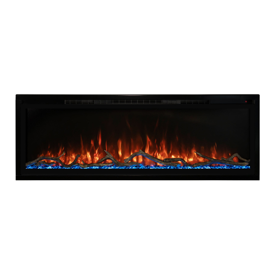
SPECTRUM SLIMLINE WALL MOUNT/RECESSED ELECTRIC FIREPLACE
Model# :
WARNING
CAUTION
AFFIX SERIAL NUMBER LABEL
HERE FOR FUTURE REFERENCE
SPS-50B-EU
SPS-74B-EU
OWNER'S MANUAL
AC 230V 50Hz 1465W (5000BTUs)
Read and understand this entire owner's manual, including all safety
information, before plugging in or using this product. Failure to do so could
result in fire, electric shock, or serious personal injury.
Keep this owner's manual for future reference. If you sell or give this
product away, make sure this manual accompanies this product.
SPS-60B-EU
SPS-100B-EU
BGM20220411.V2
Advertisement
Table of Contents

Related Manuals for Modern Flames SPECTRUM SLIMLINE SPS-50B-EU


Summary of Contents for Modern Flames SPECTRUM SLIMLINE SPS-50B-EU
- Page 1 SPECTRUM SLIMLINE WALL MOUNT/RECESSED ELECTRIC FIREPLACE Model# : SPS-50B-EU SPS-60B-EU SPS-74B-EU SPS-100B-EU OWNER’S MANUAL AC 230V 50Hz 1465W (5000BTUs) Read and understand this entire owner’s manual, including all safety information, before plugging in or using this product. Failure to do so could WARNING result in fire, electric shock, or serious personal injury.
-
Page 2: Important Safety Information
IMPORTANT SAFETY INFORMATION! WARNING ⚫ Read all instructions before installing or using this heater. Use a dedicated 10 Amp (or higher) breaker. ⚫ ⚫ This heater is hot when in use. To avoid burns, DO NOT let bare skin touch hot surfaces. If provided, use handles when moving this heater. - Page 3 ⚫ ALWAYS disconnect this unit from the power supply before performing any assembly or cleaning, or before relocating the electric fireplace. ⚫ NEVER leave this heater unattended. ALWAYS unplug this heater when not in use. ⚫ ALWAYS store this heater in a dry location. NEVER use the fireplace if it has become wet. ⚫...
-
Page 4: Parts And Hardware
Parts and Hardware B -Screws (Long) C – Drywall anchors D – Screws (short) H - Cable Connector A – Fireplace E - Side Skirt (for wall mounting) G - Remote control F- Instruction manua I - Cover Plate J - Wall Bracket M - Metal bracket for N - “L”... -
Page 5: Installation And Assembly
Installation and Assembly Your appliance is a wall-mounted, recessed, and/or mantel installed appliance. Select a suitable location that is not susceptible to moisture and is away from drapes, furniture and high traffic areas. NOTE: Follow all National and local electrical codes. MINIMUM CLEARANCE TO COMBUSTIBLES Measurements are taken from the glass front. - Page 6 Front glass removal / installation A. With one hand on the front glass to prevent it from falling, remove the two screws (1 per side) from the side of the appliance (Fig. 1-1). Set the screws aside. B. Carefully lift the front glass up and away from the appliance (Fig. 1-2 ). Place it face down on a soft, non-abrasive surface.
- Page 7 Recessed pre-installation Due to the many different materials used on different walls, it is highly recommended that you consult your local builder before you install this appliance on the wall. A. Select a location that is not prone to moisture and is located at least 36" (914mm) away from combustible materials such as curtain drapes, furniture, bedding, paper, etc.
- Page 8 Fully recessed installation A. Remove power cord and complete hardwiring (see “hardwiring installation” section). Mark location for the screws according to the dimensions as below. (Figure 2-1) C. Fix the two metal brackets (N) (1per side), with 4 screws (B) (supplied) through wood stud. (Figure 2-2) Figure 2-1 Wood...
- Page 9 D. Remove the four screws (2 per side) from the side of the appliance and remove the brackets (Fig. 2-3). Set the screw/brackets aside. Figure 2-3 E. Insert the appliance into the rough-in frame (Fig. 2-4) and then secure it by installing 4 screws (supplied) into the slots on the insides (2 per side) (Fig.
-
Page 10: Wall Mounted Installation
Wall mounted installation Due to the many different materials used on different walls, it is highly recommended that you consult your local builder before you install this appliance on the wall. NOTE: A dedicated 10 Amp (or higher) breaker is required. Select a location that is not prone to moisture and is located at least 36"... - Page 11 SPS-100B-EU Wall Bracket Illustrated SPS-50/60/74/100B Side skirt illustration Size SPS- 5-3/8" 4-1/4" 9-5/8" 3-1/4" 100B-EU [136.5mm] [108mm] [244.5mm] [82.5mm] “L” Shape bracket installation A. Remove the silver screw at the bottom of the appliance. (Fig 3-1). Set the screw aside. Fig 3-1 Fig 3-2 B.
-
Page 12: Hard Wiring Installation
Hard wiring installation WARNING TURN OFF THE APPLIANCE COMPLETELY AND LET COOL BEFORE SERVICING. ONLY A QUALIFIED SERVICE PERSON SHOULD SERVICE AND REPAIR THIS ELECTRIC APPLIANCE. HARD WIRING CONNECTION If it is necessary to hard wire this appliance, a qualified electrician must remove the cord connection, and wire the appliance directly to the household wiring. - Page 13 Driftwood Logs and Glacier Crystal installation A. Glass front must be removed and the appliance must be mounted in its final location before the driftwood logs ( M ) and glacier crystals ( L ) are installed. B. Install logs ( M ) first, then add Glacier Crystals ( L ) around logs. C.
-
Page 14: Operation
Operation Read and understand this entire owner's manual, including all safety information, before plugging in or using this product. Failure to do so could result in electric shock, fire, serious injury, or death. Power Plug the power cord into a dedicated ~230 Volt 10 Amp grounded outlet (see IMPORTANT SAFETY INFORMATION on Pages 2 and 3). - Page 15 FLAME button: Changes flame color. 1. Press once: Flame color illuminates. NOTE: Color effect stays on until power 2. Press again until desired color is button is turned off. reached. In total, ten colors for flame and one fade mode From NOTE: This fireplace has memory FLAME 01-02-03-04-05-06-07-08-09-10-11.
-
Page 16: Remote Control Operation
Remote Control Operation BUTTON FUNCTION ACTION & INDICATION ON: Enables remote control. 1. Press once: Indicator light turns on. Turns on flame. Power turns on. All functions enabled. OFF: Disables control panel functions and 2. Press again. Flame turns off. Unit goes remote control. -
Page 17: Temperature Limiting Control
1. Press once: Touch panel indicator becomes active. 2. Press again until desired temperature is reached. Digital display shows settings 0-10. Table below shows corresponding temperatures: TEMP NOTE: Press the button for 5 seconds to switch between °C and °F 1. -
Page 18: Care And Maintenance
NEVER dispose of batteries in fire. Failure to observe this precaution may result in an explosion. Dispose of batteries at your local hazardous material processing center. Care and Maintenance Cleaning ALWAYS turn the heater OFF and unplug the power cord from the outlet before cleaning, performing maintenance, or moving this fireplace. -
Page 20: Australia/New Zealand
DO NOT RETURN TO STORE! CALL US FIRST For immediate help with installation, product information or if your product arrives damaged, please call our toll-free number at: AUSTRALIA/NEW ZEALAND 07 5630 6837 (Monday - Friday, 9:00AM - 4:00PM, AEST) Or email us at: info@modernflames.com EUROPE +46 762 09 58 09...
Need help?
Do you have a question about the SPECTRUM SLIMLINE SPS-50B-EU and is the answer not in the manual?
Questions and answers