
Related Manuals for Pilz ms3p HTL


Summary of Contents for Pilz ms3p HTL
- Page 1 PNOZ ms3p HTL Configurable safety systems PNOZmulti Operating Manual 1001724-EN-04...
- Page 2 Preface This document is a translation of the original document. All rights to this documentation are reserved by Pilz GmbH & Co. KG. Copies may be made for internal purposes. Suggestions and comments for improving this documentation will be gratefully received.
-
Page 3: Table Of Contents
Connect the signals from the incremental encoder to the speed monitor 6.3.2 Connect the incremental encoder to the speed monitor via an adapter Section 7 Operation LED indicators Section 8 Technical details Safety characteristic data Operating Manual PNOZ ms3p HTL 1001724-EN-04... - Page 4 Contents Section 9 Order reference Product Accessories Section 10 Application examples 10.1 Examples without position control 10.1.1 Example 1 10.1.2 Example 2 10.2 Example with position control Operating Manual PNOZ ms3p HTL 1001724-EN-04...
-
Page 5: Operating Manual Pnoz Ms3P Htl
Introduction Introduction Validity of documentation This documentation is valid for the product PNOZ ms3p HTL. It is valid until new document- ation is published. This operating manual explains the function and operation, describes the installation and provides guidelines on how to connect the product. - Page 6 Introduction INFORMATION This gives advice on applications and provides information on special fea- tures. Operating Manual PNOZ ms3p HTL 1001724-EN-04...
-
Page 7: Overview Scope
Scope Expansion module PNOZ ms3p HTL Jumper Unit features Using the product PNOZ ms3p HTL: Speed monitor for connection to a base unit from the configurable control system PNOZmulti The product has the following features: Monitoring of 2 independent axes Connection per axis –... -
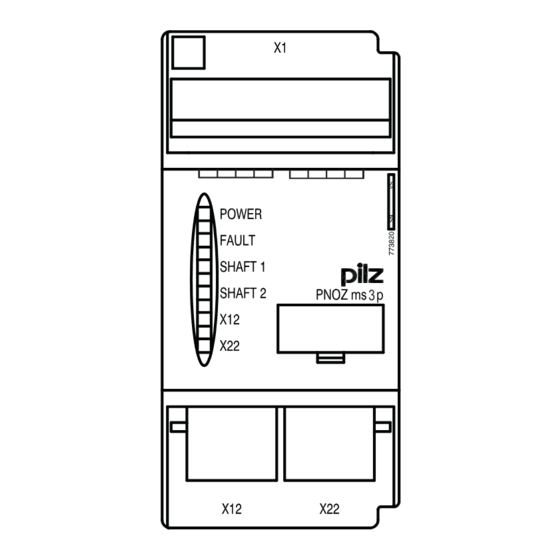
Page 8: Front View
Female connector for connecting an incremental encoder to axis 1 X22: – Female connector for connecting an incremental encoder to axis 2 LEDs: – POWER – FAULT – SHAFT 1 – SHAFT 2 – – Operating Manual PNOZ ms3p HTL 1001724-EN-04... -
Page 9: Safety
Anti-clockwise switch to a safe condition. The safe condition is cleared again as soon as the error is remedied. Hazards that can arise through an automatic restart must be excluded within the user program. Operating Manual PNOZ ms3p HTL 1001724-EN-04... -
Page 10: System Requirements
Are familiar with the basic regulations concerning health and safety / accident preven- tion Have read and understood the information provided in this description under "Safety" And have a good knowledge of the generic and specialist standards applicable to the specific application. Operating Manual PNOZ ms3p HTL 1001724-EN-04... -
Page 11: Warranty And Liability
Do not open the housing or make any unauthorised modifications. Please make sure you shut down the supply voltage when performing maintenance work (e.g. exchanging contactors). Operating Manual PNOZ ms3p HTL 1001724-EN-04... -
Page 12: Function Description
Incremental encoders may be used to record the values. The configuration of the speed monitor is described in detail in the PNOZmulti Configur- ator's online help. Block diagram RJ45 RJ45 Operating Manual PNOZ ms3p HTL 1001724-EN-04... -
Page 13: Incremental Encoders
The adapter records the data between the encoder and drive and makes it available to the PNOZ ms3p HTL via the RJ45 socket. Pilz supplies complete adapters as well as ready-made cable with RJ45 connector, which can be used when making your own adapter. The range of products in this area is con- stantly being expanded. -
Page 14: Installation
Damage due to electrostatic discharge! Electrostatic discharge can damage components. Ensure against discharge before touching the product, e.g. by touching an earthed, conductive sur- face or by wearing an earthed armband. Dimensions 94 (3.70") (1.77") Operating Manual PNOZ ms3p HTL 1001724-EN-04... -
Page 15: Connecting The Base Unit And Expansion Modules
Please refer to the document "PNOZmulti System Expansion" for details of the number of modules that can be connected to the base unit and the module types. Operating Manual PNOZ ms3p HTL 1001724-EN-04... -
Page 16: Commissioning
The configuration of the switch-off delay must be considered in the risk assessment as regards haz- ards, reaction time and safety distance. Pin assignment of RJ45 socket RJ45 socket 8-pin Track Operating Manual PNOZ ms3p HTL 1001724-EN-04... -
Page 17: Connecting The Incremental Encoder
Supply voltage (12 V – 30 V) to incremental encoder only. HTL signals may not be fitted with a terminating resistor. Operating Manual PNOZ ms3p HTL 1001724-EN-04... - Page 18 Adapter Incremental Drive 24 V 24 V DC encoder Speed monitor Fig.: Connection via adapter and drive Adapter Incremental 24 V 24 V DC encoder Speed monitor Fig.: Connection via adapter Operating Manual PNOZ ms3p HTL 1001724-EN-04...
-
Page 19: Operation
The LEDs “POWER”, “DIAG”, “FAULT”, “IFAULT” and “OFAULT” will light up on the base unit. The PNOZmulti safety system is ready for operation when the "POWER" and "RUN" LEDs on the base unit and the "READY" LED on the PNOZ ms3p HTL are lit continuously. LED indicators Legend... -
Page 20: Technical Details
EN 60068-2-1/-2 Temperature range -25 - 70 °C Climatic suitability EN 60068-2-30, EN 60068-2-78 In accordance with the standard Humidity 93 % r. h. at 40 °C Condensation during operation Not permitted EN 61131-2 Operating Manual PNOZ ms3p HTL 1001724-EN-04... - Page 21 0,25 - 0,75 mm², 24 - 20 AWG Spring-loaded terminals: Terminal points per connec- tion Stripping length with spring-loaded terminals 9 mm Dimensions Height 94,0 mm Width 45,0 mm Depth 121,0 mm Weight 211 g Operating Manual PNOZ ms3p HTL 1001724-EN-04...
-
Page 22: Safety Characteristic Data
A safety function's SIL/PL values are not identical to the SIL/PL values of the units that are used and may be different. We recommend that you use the PAScal software tool to calculate the safety function's SIL/PL values. Operating Manual PNOZ ms3p HTL 1001724-EN-04... -
Page 23: Order Reference
1 set of spring-loaded terminals 783 800 Set screw terminals 1 set of screw terminals 793 800 Terminator, jumper Product type Features Order no. PNOZmulti bus terminator Terminator 779 110 KOP-XE Jumper 774 639 Operating Manual PNOZ ms3p HTL 1001724-EN-04... -
Page 24: Application Examples
The bit is evaluated as follows: The connection point "Input Device OK" must be incorporated into the application and eval- uated in such a way that a shutdown occurs if the connection point "Input Device OK"= 0. Operating Manual PNOZ ms3p HTL 1001724-EN-04... - Page 25 If no feasible signals above standstill frequency are measured within this time, a shut- down will occur. In this case, the bit will be evaluated as follows: Please note that the direction of rotation must be evaluated for this example! Operating Manual PNOZ ms3p HTL 1001724-EN-04...
-
Page 26: Example With Position Control
During operation, diagnostic bit 10 must be evaluated in the user program in such a way that a set bit leads to a safety-related error reaction (shutdown). Application example: Enable PNOZ ms3p PNOZmulti Base Unit ms4p Position Control Operating Manual PNOZ ms3p HTL 1001724-EN-04... - Page 27 2 s after leaving standstill. The connection point "Input Device OK" must be incorporated into the application and eval- uated in such a way that a shutdown occurs if the connection point "Input Device OK"= 0. Operating Manual PNOZ ms3p HTL 1001724-EN-04...
Need help?
Do you have a question about the ms3p HTL and is the answer not in the manual?
Questions and answers