Ross ULTRIX-FR12 Installation Manual
Hide thumbs
Also See for ULTRIX-FR12:
- Replacing (4 pages) ,
- Installing and cabling (2 pages) ,
- Manual (2 pages)
Table of Contents
Advertisement
Quick Links
Advertisement
Table of Contents

Subscribe to Our Youtube Channel
Related Manuals for Ross ULTRIX-FR12


Summary of Contents for Ross ULTRIX-FR12
- Page 1 ULTRIX-FR12 Installation Guide...
- Page 2 Ross has become well known for the Ross Video Code of Ethics. It guides our interactions and empowers our employees. I hope you enjoy reading it below. If anything at all with your Ross experience does not live up to your expectations be sure to reach out to us at solutions@rossvideo.com.
- Page 3 Ross Video. While every precaution has been taken in the preparation of this document, Ross Video assumes no responsibility for errors or omissions. Neither is any liability assumed for damages resulting from the use of the information contained herein.
- Page 4 Cet appariel numerique de la classe “A” est conforme a la norme NMB-003 du Canada. Notice — Changes or modifications to this equipment not expressly approved by Ross Video Ltd. could void the user’s authority to operate this equipment. European Union...
- Page 5 At the discretion of Ross, and on a temporary loan basis, plug in circuit boards or other replacement parts may be supplied free of charge while defective items undergo repair. Return packing, shipping, and special handling costs are the responsibility of the customer.
- Page 6 If you need more information on the collection, reuse, and recycling systems, please contact your local or regional waste administration. You can also contact Ross Video for more information on the environmental performances of our products. This appliance may contain a Coin type battery which should not be treated as household waste.
-
Page 7: Table Of Contents
Rear Panel Overview ..........................17 Physical Installation Before You Begin ............................21 Unpacking the Equipment ........................21 Mounting Requirements ........................22 Connecting the ULTRIX-FR12 to a Network ................... 22 Powering the ULTRIX-FR12 Overview ..............................25 Before You Begin ........................... 25 Workflow for Initial Power Up ......................... - Page 8 Connecting the SFP Ports ........................39 Working with Fiber Optic Connectors ....................39 Cabling for IP Streaming .......................... 40 Connecting to an Ultricore BCS ......................41 Connecting to a Ross NK Series Device ....................42 Cabling Designations ULTRIX-HDX-IO Blade ..........................43 ULTRIX-HDBNC-IO Blade ......................... 44 ULTRIX-IP-IO Blade ...........................
-
Page 9: Introduction
• “Software Licenses” provides third-party software license information for your ULTRIX-FR12. If you have questions pertaining to installation of this Ross Video product, please contact us at the numbers listed in “Contacting Technical Support”. Our technical staff is always available for consultation, training, or service. -
Page 10: Referenced Guides
Contacting Technical Support At Ross Video, we take pride in the quality of our products, but if problems occur, help is as close as the nearest telephone. Our 24-hour Hot Line service ensures you have access to technical expertise around the clock. -
Page 11: Getting Started
ETHERNET RCP-NKM Remote Control Panel T-BUS PC running DashBoard NK-NET NK-3G-16 T-BUS to Ethernet Adapter 16x16 3G/HD/SD SDI Router T-BUS INPUTS OUTPUTS VID REF NK-NET Figure 1 Example of a Routing System ULTRIX-FR12 Installation Guide (v4.0) Getting Started • 11... -
Page 12: Signal Distribution
Each physical router (or signal type) may be thought of as a layer or level of the routing system (e.g. a video level, an audio level). ULTRIX-FR12 can assign a level to a matrix or signal type and even individual ports on unrelated matrices if required. -
Page 13: Hardware Overview
Hardware Overview This chapter outlines the features of the ULTRIX-FR12, including the front and rear panels. For More Information on... • other Ultrix routers, refer to the ULTRIX-NS-FR1, ULTRIX-NS-FR2, and ULTRIX-FR5 Installation Guide. Features The ULTRIX-FR12 includes the following features: •... -
Page 14: Front Panel Overview
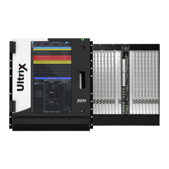
channels in and out Front Panel Overview The ULTRIX-FR12 is designed to operate with the door closed to ensure adequate cooling via the fans. Caution — Before opening the front panel door, ensure that the ULTRIX-FR12 is disconnected from the power source and fully powered off. - Page 15 Figure 2 Example of an ULTRIX-FR12 —Front Panel 1) Front Panel Wave Light 3) ENET Port LEDs 2) Display Panel 4) USB Port 1. Front Panel Wave Light The front panel provides various system status indication via the 'wave light'. The concave section of the black front panel bezel emits light of various colors to indicate system function.
- Page 16 3. ENET Port LEDs Table 4 describes the two ULTRIX-FR12 front panel LEDs that are used to monitor ethernet communication activity of the router. When facing the front panel, the left LED reports the status of the ENET 1 port while the right LED reports the status of the ENET 2 port. Refer to “Rear Panel Overview”...
-
Page 17: Rear Panel Overview
Note that the number of populated slots in your router may differ from what is presented here. 2 3 4 5 6 7 10 11 13 14 15 16 Figure 3 Example of an ULTRIX-FR12 — Rear Panel 1) PSU Connections 4) ULTRIX-HDX-IO Blade 7) ULTRIX-IP-IO Blade 10) Protective Earth Stud... - Page 18 1. PSU Connections There are four power input modules located on the back of the ULTRIX-FR12. Each input module includes four power connectors that correspond to the four connectors on an Ultripower power supply. Caution — The ULTRIX-FR12 requires a minimum of two Ultripower units and has a specific power up process.
- Page 19 Each ULTRIX-SFP-IO blade provides two AUX ports, and sixteen SFP ports. Each port can be populated with Small Form-factor Pluggable (SFP+) modules from the factory or by installing modules in the field. For a list of SFP+ modules available from Ross Video, refer to Table 2. 6. ULTRIX-IPX-IO Blade Each ULTRIX-IPX-IO blade provides four QSFP28 ports with 100GbE bandwidth per port.
- Page 20 20 • Hardware Overview ULTRIX-FR12 Installation Guide (v4.0)
-
Page 21: Physical Installation
Before You Begin Caution — The ULTRIX-FR12 utilizes front-to-back airflow management (looking at the front of the chassis). It is a requirement that the front and back of the mounted ULTRIX-FR12 router are not obscured. These installation guidelines assume the following: •... -
Page 22: Mounting Requirements
Adequate ventilation within a rack frame must also be maintained. • The ULTRIX-FR12 mounts in the rack frame by means of rack screws fastened through the front and back mounting ears. This should normally be sufficient to carry the load, including the weight of accompanying cables. - Page 23 Connect one free end of a standard CAT 5/5e/6 Ethernet cable to a free port of the network hub. b. Connect the other end of the same cable to the ENET 1 port on the rear of the ULTRIX-FR12 router.
- Page 24 24 • Physical Installation ULTRIX-FR12 Installation Guide (v4.0)
-
Page 25: Powering The Ultrix-Fr12
Powering the ULTRIX-FR12 If you have questions pertaining to the installation of your ULTRIX-FR12, contact us at the numbers listed in “Contacting Technical Support”. Notice — We recommend that the equipment be installed by qualified and experienced service personnel, to any relevant standards and approvals. -
Page 26: Ultripower Manager
— The Ultripower units must be grouped prior to connecting the power connections to the ULTRIX-FR12 chassis. The ULTRIX-FR12 requires multiple Ultripower power supply units (with a minimum of two units). It is required that these power cycle together. The primary Ultricore BCS has the Ultripower Manager feature to group up to 4 Ultripower units. - Page 27 If you are setting up a redundant system or a high-powered system, you will need to include 4 Ultripower units to the group. In the example above, the user created two Ultripower groups. 20. Click OFF. ULTRIX-FR12 Installation Guide (v4.0) Powering the ULTRIX-FR12 • 27...
-
Page 28: Cabling The Ultripowers To The Ultrix-Fr12
— The Ultripower group must be set to OFF before connecting to the ULTRIX-FR12. There are 16 PSU sockets organized into 4 groups on the back of each ULTRIX-FR12. Each PSU group connects to one Ultripower Rack Mount Power Supply unit. Each Ultripower is a 1RU 1200W power supply specifically designed for the Ultrix series routers. - Page 29 Connect the ends of four power cables to the third Ultripower rear panel OUT sockets. b. Connect the free ends of the same power cables to the ULTRIX-FR12 rear panel. 2. To connect a fourth Ultripower to the ULTRIX-FR12: a.
- Page 30 13 14 15 16 Rack Mount Power Supply Unit Rack Mount Power Supply Unit RESTART RESTART Rack Mount Power Supply Unit Rack Mount Power Supply Unit Figure 5 ULTRIX-FR12 — Power Connections 30 • Powering the ULTRIX-FR12 ULTRIX-FR12 Installation Guide (v4.0)
-
Page 31: Powering On The Ultrix-Fr12 Via Dashboard
Notice — The ULTRIX-FR12 does not have a physical power switch. The ULTRIX-FR12 is powered on via the controlling Ultricore BCS interface. To toggle the Ultripower Group to ON 1. Locate the Ultricore BCS node in the Tree View of DashBoard. - Page 32 32 • Powering the ULTRIX-FR12 ULTRIX-FR12 Installation Guide (v4.0)
-
Page 33: Cabling Your Router
The conditions that generate an alarm are critical incidents that stop the ULTRIX-FR12 from working. If the ULTRIX-FR12 is not supervised or at a remote site, such an alarm is used to alert system technicians that a failure has occurred, or the alarm can be used to trigger a backup system. -
Page 34: Connecting The Video Reference Source
• supported reference formats for Frame Sync/Clean Switch, refer to “Supported FSCS Video Formats for Conversion”. Reference Cabling for the ULTRIX-FR12 The ULTRIX-FR12 consists of two independent reference connections (REF A, REF B). Each may be configured for loop-through or terminating functionality. The ULTRIX-FR12 requires at least one reference connection. -
Page 35: Cabling For An Ultriscape Head
Figure 6 ULTRIX-FR12 — DIP Switch in the TERM Positions Cabling for an UltriScape Head The number of UltriScape (Multiviewer) Heads for your ULTRIX-FR12 router depends on the number of UltriScape licenses enabled and the total number slots populated with I/O blades. Table 7 lists the connections on the rear panel that are available for UltriScape Heads based on the type of blade installed in the slot. - Page 36 Connect the end of a 75ohm coaxial cable with an HD-BNC connector on one end to an OUT HD-BNC on the ULTRIX-FR12 rear panel. b. Connect the other end of the coaxial cable to the device that displays the UltriScape Head from that OUT HD-BNC on the router.
-
Page 37: Connecting Source Devices
Third Party Matrices, Sources, and Destinations tabs of the database). 1. Requires installing an Ultrispeed license key for each slot. Refer to the ULTRIX-FR12 User Guide for details. 2. Requires installing an Ultrispeed license key for each slot. Refer to the ULTRIX-FR12 User Guide for details. -
Page 38: Outputs
• supported video formats for a Gearbox, refer to “Supported Video Formats”. Outputs When you configure a Gearbox output group, ULTRIX-FR12 takes the signals of the four 3G Level A channels together and provides a single 12G signal to an output. -
Page 39: Inputs
Inputs When you enable a Gearbox input group, ULTRIX-FR12 multiplexes the signals of the four 3G Level A channels together. Table 9 Gearbox Mapping — Default Input Groups on the Ultrix HDX-IO Group Channel 1 Channel 2... -
Page 40: Cabling For Ip Streaming
2. Ensure that the exposed surface of the ceramic ferrule of each connector is clean. Refer to “Working with Fiber Optic Connectors” for cleaning tips. 3. Cable your SFP+ module as required. (Figure 11) 40 • Cabling Your Router ULTRIX-FR12 Installation Guide (v4.0) -
Page 41: Connecting To An Ultricore Bcs
For More Information on... • configuring the senders and receivers for the blade, refer to the ULTRIX-FR12 User Guide. • ULTRIX-IP-IO blade, refer to “Cabling Designations”. • ULTRIX-IPX-IO blade, refer to “Cabling Designations”. Connecting to an Ultricore BCS An Ultricore BCS is required when using an ULTRIX-FR12. This allows for connectivity and router control, and database configuration. -
Page 42: Connecting To A Ross Nk Series Device
To establish communications between a Ross NK device and your ULTRIX-FR12 1. Connect the NK device to the same Ethernet network as your ULTRIX-FR12 router using an NK-NET or an NK-IPS. The NK-NET requires a Ross NK router to supply phantom power for operation. -
Page 43: Cabling Designations
This section outlines the implemented cabling designations for an ULTRIX-HDX-IO blade. Figure 15 SDI Inputs Figure 16 SDI Outputs Figure 17 AUX Ports AUX D is only required for the UltriStream licensed feature. Refer to the Ultrix User Guide for details. ULTRIX-FR12 Installation Guide (v4.0) Cabling Designations • 43... -
Page 44: Ultrix-Hdbnc-Io Blade
HD-BNCs are numbered starting at IN 1. (Figure 18) Destination connections on the ULTRIX-HDBNC-IO blade are located on the bottom of each blade. The HD-BNCs are numbered starting at OUT 1. (Figure 19) 44 • Cabling Designations ULTRIX-FR12 Installation Guide (v4.0) -
Page 45: Ultrix-Ip-Io Blade
This section outlines the default cabling designations for an ULTRIX-IP-IO blade. ENET 4 (PORT 4) ENET 3 (PORT 3) AUX 2 AUX 1 ENET 2 (PORT 2) ENET 1 (PORT 1) Figure 21 IP Ports Figure 22 AUX Ports ULTRIX-FR12 Installation Guide (v4.0) Cabling Designations • 45... -
Page 46: Ultrix-Ipx-Io Blade
100GBASE-SR4, 100GBASE-SWDM4, 100GBASE-PSM4, 100GBASE-CWDM4, 100GBASE-4WDM-10/20/40, and 100GBASE-CLR4. Contact Ross Technical Support for details on support for other transceiver types. Cabling This section outlines the default cabling designations for an ULTRIX-IPX-IO blade. - Page 47 The AUX C and AUX D ports are not implemented in the Ultrix v5.1.5 software. PSU Port The power supply connector requires a 15VDC connection to an external power supply. (Figure 25) Refer to the Ross Configuration Tool on our website for the power requirements of your configuration. USB Port The USB Type B port is used for recovery only.
-
Page 48: Ultrix-Sfp-Io Blade
The ULTRIX-SFP-IO blade provides up to 16 ports that can be populated with supported SFP+ modules. This section outlines the default cabling designations for an ULTRIX-SFP-IO blade. AUX B AUX A Figure 27 SFP Ports Figure 28 AUX Ports 48 • Cabling Designations ULTRIX-FR12 Installation Guide (v4.0) -
Page 49: Technical Specifications
Technical Specifications This chapter provides technical information for ULTRIX-FR12. Note that specifications are subject to change without notice. Physical Dimensions Table 10 Technical Specifications — Physical Dimensions Item Specification Width 18.90” (48cm) Depth 15.91” (40.41cm) Height 21.0” (53.34cm) Weight (approx.) 122lbs (55.34kg) -
Page 50: Supported Fscs Video Formats For Conversion
720p 50Hz 1080p Level A 50Hz 1080p Level B 50Hz 2160p 50Hz 59.94Hz 720p 59.94Hz 1080p Level A 59.94Hz 1080p Level B 59.94Hz 2160p 59.94Hz 60Hz 720p 60Hz 1080p 60Hz 2160p 60Hz 50 • Technical Specifications ULTRIX-FR12 Installation Guide (v4.0) - Page 51 2160p 59.94Hz 60Hz 720p 30Hz 720p 60Hz 1080i 60Hz 1080p 30Hz 1080p Level A 60Hz 1080p Level B 60Hz 1080pSF 30Hz 2160p 30Hz 2160p 60Hz 1080p 23.98Hz 1080p 23.98Hz 24Hz 1080p 24Hz ULTRIX-FR12 Installation Guide (v4.0) Technical Specifications • 51...
- Page 52 The Frame Sync does not support 720p dual stream 60/59.94/50 formats. The Clean Switch does. b. The Frame Sync does not support 1080i dual stream 60/59.94/50 formats. The Clean Switch does. c. The Frame Sync does not support 1080pSF 30/29.97/25 formats. The Clean Switch does. 52 • Technical Specifications ULTRIX-FR12 Installation Guide (v4.0)
-
Page 53: Supported Video Formats
1080 59.94 1080 1080 Level B 1080 Level B 59.94 1080 Level B 6G (UHD) ULTRIX-FR12 Installation Guide (v4.0) Technical Specifications • 53... -
Page 54: Maximum Power Ratings
Refer to the Ultrix Configuration Tool for details on the required number of Ultripower Power Supply units for the ULTRIX-FR12. Table 14 outlines the maximum power ratings for fully loaded ULTRIX-FR12. Table 14 Technical Specifications — Maximum Power Ratings Item... -
Page 55: Outputs
Refer to the Ultrix SFP Modules Guide. Embedded Audio Table 17 Technical Specifications — Audio Inputs Item Specification Audio Channels per SDI I/O Audio Channels per MADI I/O Selectable 56 or 64 ULTRIX-FR12 Installation Guide (v4.0) Technical Specifications • 55... -
Page 56: Environmental
1080p 59.94Hz Ethernet Port Connectors Each ULTRIX-FR12 router comes standard with two Ethernet ports. Each port uses a standard single 8-pin, RJ45 connector to interface to an 802.3x Ethernet network. While ULTRIX-FR12 supports 1000Mbps (1GbE), 100Mbps, or 10Mbps network interface speeds, an 1GbE network connection is required. -
Page 57: Supported Sfp Modules
• Belkin Supported SFP Modules Some of the blades installed in the ULTRIX-FR12 rear panel can be populated with specific classes of small form-factor pluggable (SFP) modules. Refer to the Ultrix SFP Modules Guide for more information on the SFP models and their specifications. - Page 58 58 • Technical Specifications ULTRIX-FR12 Installation Guide (v4.0)
-
Page 59: Software Licenses
Software Licenses This chapter provides third-party software license information for your ULTRIX-FR12 router. This product includes multiple software components which are individually licensed under one or more of the following licenses included in this chapter. Copyright (c) 1991,1993, The Regents of the University of California. All rights reserved. - Page 60 “aggregate” if the compilation and its resulting copyright are not used to limit the access or legal rights of the compilation's users beyond what the individual works permit. Inclusion of a covered work in an aggregate does not cause this License to apply to the other parts of the aggre- gate. 6.Conveying Non-Source Forms. 60 • Software Licenses ULTRIX-FR12 Installation Guide (v4.0)
- Page 61 Additional terms, permissive or non-permissive, may be stated in the form of a separately written license, or stated as exceptions; the above requirements apply either way. 8.Termination. ULTRIX-FR12 Installation Guide (v4.0) Software Licenses • 61...
- Page 62 Each version is given a distinguishing version number. If the Program specifies that a certain numbered version of the GNU General Public License “or any later version” applies to it, you have the option of following the terms and conditions either of that numbered version or of any 62 • Software Licenses ULTRIX-FR12 Installation Guide (v4.0)
- Page 63 Program, unless a war- ranty or assumption of liability accompanies a copy of the Program in return for a fee. ULTRIX-FR12 Installation Guide (v4.0) Software Licenses • 63...
-
Page 64: Lgpl
The Free Software Foundation may publish revised and/or new versions of the GNU Lesser General Public License from time to time. Such new versions will be similar in spirit to the present version, but may differ in detail to address new problems or concerns. 64 • Software Licenses ULTRIX-FR12 Installation Guide (v4.0) -
Page 65: Mit
The data format used by the zlib library is described by RFCs (Request for Comments) 1950 to 1952 in the files ftp://ds.inter- nic.net/rfc/rfc1950.txt (zlib format), rfc1951.txt (deflate format) and rfc1952.txt (gzip format). ULTRIX-FR12 Installation Guide (v4.0) Software Licenses • 65... - Page 66 66 • Software Licenses ULTRIX-FR12 Installation Guide (v4.0)
-
Page 67: Glossary
Glossary The following terms are used throughout this guide: Connection Point — setting to define a communication connection between an ULTRIX-FR12 and a device in the routing system. Crosspoint — a switch within a matrix. For example, the connection of signal IN 1 to OUT 1 requires one crosspoint. - Page 68 68 • Glossary ULTRIX-FR12 Installation Guide (v4.0)
Need help?
Do you have a question about the ULTRIX-FR12 and is the answer not in the manual?
Questions and answers