Table of Contents
Advertisement
Quick Links
Advertisement
Table of Contents
Troubleshooting

Related Manuals for Ross Master Control MC1-PANEL-16


Summary of Contents for Ross Master Control MC1-PANEL-16
- Page 1 MC1-PANEL-16 User Guide...
- Page 2 Ross has become well known for the Ross Video Code of Ethics. It guides our interactions and empowers our employees. I hope you enjoy reading it below. If anything at all with your Ross experience does not live up to your expectations be sure to reach out to us at solutions@rossvideo.com.
- Page 3 Ross Video. While every precaution has been taken in the preparation of this document, Ross Video assumes no responsibility for errors or omissions. Neither is any liability assumed for damages resulting from the use of the information contained herein.
- Page 4 Cet appariel numerique de la classe “A” est conforme a la norme NMB-003 du Canada. Notice — Changes or modifications to this equipment not expressly approved by Ross Video Ltd. could void the user’s authority to operate this equipment. European Union This equipment is in compliance with the essential requirements and other relevant provisions established under regulation (EC) No 765/2008 and Decision No 768/2008/EC referred to as the “New Legislative Framework”.
- Page 5 Company Address Ross Video Limited Ross Video Incorporated 8 John Street P.O. Box 880 Iroquois, Ontario, K0E 1K0 Ogdensburg, New York Canada USA 13669-0880 General Business Office: (+1) 613 • 652 • 4886 Fax: (+1) 613 • 652 • 4425 Technical Support: (+1) 613 •...
-
Page 7: Table Of Contents
Contents Introduction Related Publications ..............................9 Documentation Conventions ............................ 9 Interface Elements ..............................9 User Entered Text ..............................9 Referenced Guides ..............................9 Menu Sequences ..............................10 Important Instructions ............................10 Contacting Technical Support ..........................10 Before You Begin Overview ................................11 Features .................................. - Page 8 Mnemonic Display ..............................29 LCD Display ................................30 Loading the Factory Defaults ..........................30 To reset the card to the factory default settings in DashBoard ................ 30 Assigning an MC1-MK Card to a Channel Button ....................30 Configuring the Channel Personality ........................31 Specifying the Number of Available Crosspoints ....................31 Displaying the On Air Control Interface ......................32 Disabling the Fade to Black Button ........................32 Color Schemes ..............................33...
-
Page 9: Introduction
• “Service Information” provides information on the warranty and repair policy for your panel. • “Glossary” provides a list of terms used throughout this guide. Related Publications It is recommended to consult the following Ross documentation before installing and configuring your MC1-PANEL-16: • DashBoard User Manual, Ross Part Number: 8351DR-004 •... -
Page 10: Menu Sequences
IP Address, Subnet Mask, and Gateway for your device. Contacting Technical Support At Ross Video, we take pride in the quality of our products, but if problems occur, help is as close as the nearest telephone. -
Page 11: Before You Begin
Before You Begin This chapter provides a basic introduction to the MC1-PANEL-16, including an overview of the different areas of the control panel, and the DashBoard interfaces. Overview The MC1-PANEL-16 is a stand-alone control panel that provides all the basic user input for the MC1-MK card (channel) it is controlling. -
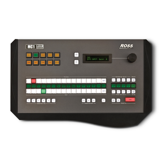
Page 12: Control Panel Overview
Control Panel Overview This section provides a basic introduction to the MC1-PANEL-16, including an overview of the different areas on the control panel. AUTO Eff4 ONAIR GAIN: 0 PROGRAM PROGRAM PROGRAM KEY SELECT PROGRAM KEY SELECT PGM AO PGM AO AUDIO AUDIO SHIFT... -
Page 13: Physical Connections
3. Micro SD Card Slot This slot is used in the case of a software upgrade failure and under the guidance of Ross Technical Support. This slot is not populated with a micro SD card when shipped from the factory. -
Page 14: Interfaces Overview
If the MC1-PANEL-16 fails to upgrade correctly, contact Ross Technical Support for an upgrade file and instructions on using the Micro SD Card slot. 4. PMC Link Connections There are two Panel Module Controller (PMC) Link ports are used to connect to external modules. These ports are reserved for future use. -
Page 15: Active Channel On Air Control Interface
From this interface you can: • set up ethernet communications for the panel • assign channels (MC1-MK cards) to buttons on the panel • create a custom panel color scheme • customize the mnemonic contrast and color • monitor the status of the MC1-PANEL-16 hardware including power supply voltage Active Channel On Air Control Interface When a button on the MC1-PANEL-16 is selected and communicating with an MC1-MK card (channel),... - Page 16 16 • Before You Begin MC1-PANEL-16 User Guide (v4.0)
-
Page 17: Physical Installation
Before you begin, ensure that you are using DashBoard version 6.2.0 or higher and that your MC1-MK cards are running software version 5.0 or higher. The DashBoard Control System software and user manual are available to download from the Ross Video website. Static Discharge... -
Page 18: Installing The Mc1-Mk Cards Overview
Third-Party Controller Automation Protocol PORT 1 Network Switch Master Control LAN / VPN PORT 1 PORT 2 PORT 3 PORT 4 PORT 5 PORT 6 PORT 7 PORT 8 PC running DashBoard Comtrol Devicemaster EAS-911 Emergency Alert System Encoder AUDIO J102 OUTPUT AUDIO INPUT... -
Page 19: Ethernet Cabling
Set up of ethernet connections between the devices, such as a router, and the MC1-MK cards are outlined in the MC1-MK Installation Guide. Ross Video strongly recommends installing your Master Control System on a network that is segregated from your facility LAN. Ethernet Cabling for the MC1-PANEL-16... -
Page 20: Setting The Dip Switches
PS 1 PS 2 MODE PMC LINK ETHERNET To Ethernet Network Figure 3.2 MC1-PANEL-16 — Ethernet Connection Setting the DIP Switches This section briefly summarizes the DIP Switch settings on the MC1-PANEL-16. Refer to Figure 3.2 for the locations. Note that Figure 3.3 shows the DIP Switches in the UP position. Figure 3.3 DIP Switches —... -
Page 21: Sw4 - Bootload Method
SW4 — Bootload Method should be left in the default UP position unless otherwise directed by Ross Technical Support. Power Connections The MC1-PANEL-16 comes standard with one power supply, with a second optional power supply available for redundancy. For redundancy, and in applications where the equipment is used in a critical signal path, we recommend that two power supplies be used in the MC1-PANEL-16. -
Page 22: Control Panel Button Inserts
Insert films can be installed into most buttons on the MC1-PANEL-16. Insert films allow you to label specific source buttons, control buttons, or replace the default button names with those of a different language. Button insert template can be downloaded from Ross Video. To install a button insert Remove the Cap Assembly from the Switch Assembly by grasping it firmly and pulling away from the control panel surface. -
Page 23: Using Dashboard
To launch DashBoard Ensure that you are running DashBoard software version 6.2.0 or higher. The software and DashBoard User Guide are available from the Ross Video website. Launch DashBoard by double-clicking its icon on your desktop. Locate the MC1-PANEL-16 in the Tree View of DashBoard. If the MC1-PANEL-16 node does not appear, consult the DashBoard User Guide. - Page 24 24 • Using DashBoard MC1-PANEL-16 User Guide (v4.0)
-
Page 25: Configuration
Before proceeding, ensure that you are running DashBoard software version 6.2.0 or higher. The DashBoard software and user manual are available to download from the Ross Video website. Before You Begin Ensure that the following tasks are performed for each MC1-MK card that the MC1-PANEL-16 will communicate with: Select the Sources —... -
Page 26: Troubleshooting
To run in DHCP Mode If you wish to run in DHCP mode only, set DOWN To run in Static Mode Configure the new settings as outlined in the section “Custom User Configuration via DashBoard” on page 26. To verify the IP address of the MC1-PANEL-16 Verify that the correct IP address is reported on the MC1-PANEL-16 LCD Display. -
Page 27: Automatic Configuration Using Dhcp
To change between Static and DHCP addressing, select an option in the Method area. If you chose Static in step 4, configure the network settings as required for you facility: • IP Address — This is the IP Address of the MC1-PANEL-16. Contact your IT Department to receive a unique IP address for your MC1-PANEL-16. -
Page 28: Mc1-Panel-16 Personality
Check the link/activity LEDs found on the ethernet RJ-45 connectors. c. Verify that you have properly performed each step of this procedure. d. Contact Ross Video Technical Support if you cannot establish a connection. 11. Once communication is established: a. -
Page 29: Configuring The Edit Permissions
Type a unique identifier in the Panel Name field. Press to apply the new name. Enter Configuring the Edit Permissions You choose to lock the MC1-PANEL-16 permissions so that all configurable parameters are read-only and cannot be changed. To configure the card edit permissions From the Tree View, expand the node for the MC1-PANEL-16 you want to access. -
Page 30: Lcd Display
To modify the mnemonic display for a channel From the Tree View, expand the node for the MC1-PANEL-16 you want to access. Select the Configuration node to display the interface in the right-half of DashBoard. Select the Channel, Mnemonic, LCD tab. Use the Mnemonic Contrast field to specify the difference in brightness between the text and the background of the mnemonic display. -
Page 31: Configuring The Channel Personality
Locate the MC1-MK card you wish to assign to the MC1-PANEL-16 Channel button as follows in the Tree View. Drag and drop the MC1-MK card node to the required button on the MC1-MK Panel Channel, Channel Mnemonic, LCD tab. The button now displays the logo for the assigned MC1-MK card. Type a unique identifier in the Channel Name field. -
Page 32: Displaying The On Air Control Interface
To specify the number of available crosspoints Locate the MC1-MK card in the Tree View. Select the Configuration node to display the Configuration interface for that card. Select the Config tab. Select the Personality tab. Use the Number of Crosspoint Buttons slider to specify: •... -
Page 33: Color Schemes
To disable the FTB button Locate the MC1-MK card in the Tree View. Select the Configuration node to display the Configuration interface for that card. Select the Config tab. Select the Personality tab. To disable the button, select the Disable FTB box. Color Schemes The buttons on the MC1-PANEL-16 can be set to glow with a custom color, you can choose what color denotes an on air button. - Page 34 The Transparency menu is not implemented. Use the Hue options to specify whether the color is red yellow, green, blue, purple etc. Or you can select the hue from the provided vertical color grid in the dialog. Use the Saturation options to specify the depth of the color. 10.
-
Page 35: Operation
To access the Active Channel On Air Control interface Ensure that you are running DashBoard software version 6.2.0 or higher. The software and DashBoard User Guide are available from the Ross Video website. Launch DashBoard by double-clicking its icon on your desktop. -
Page 36: Selecting A Master Control Channel
There are two methods for re-establishing communications: using Auto Discovery, and manually adding the frame using its IP address. This section briefly outlines how to use both methods. To use auto discovery • Perform one of the following: › Use the Auto Discovery feature in DashBoard to quickly refresh communications and the list of devices listed in the Tree View. -
Page 37: Channel Ganging
Channel Ganging Each MC1-MK can operate as either master or remote channel depending on the role assigned to it in the Remote Control tab of its Configuration interface. The master MC1-MK passes all supported commands to each remote MC1-MK with a valid connection to it. When channel ganging is enabled, the Home tab of the MC1-MK reports its channel gang status on the same line as the EAS Status (located at the bottom of the Home tab). - Page 38 › The middle row includes mnemonics that display › The bottom row of buttons, labeled Key 1-4, are used to add, or remove, the specified keyer to the next transition. Selecting the button toggles the keyer on/off and selects/removes the keyer to the Preset Bus respectively.
-
Page 39: Performing Transitions
Performing Transitions You can perform transitions in one of the following manners: hot-punching a crosspoint on the Program bus, selecting a Keyer (1-4) button from the Keyer Area to transition a keyer on or off air, and using the options in the Transition Area to add elements to the transition. -
Page 40: Performing Transitions With Squeezeback Presets
AUTO Eff4 Eff4 ONAIR ONAIR GAIN: 0 GAIN: 0 PROGRAM PROGRAM KEY SELECT PGM AO AUDIO KEY 1 KEY 2 KEY 3 KEY 4 SHIFT OVER AUDIO KEY 1 KEY 2 KEY 3 KEY 4 SHIFT OVER PRESET PRESET KEY SELECT PST AO BKGD SLOW... -
Page 41: Previewing A Squeeze Effect
• You can also trigger a squeeze effect using a GPI trigger. Refer to the MC1-MK Installation Manual for setup details. • You can configure a tally to raise when the reveal source is visible. This tally will be raised regardless of the configured source. -
Page 42: Overview
Overview MC1-PANEL-16 includes four high quality HD/SD-SDI video keyer. In addition to the external Key Video and Key Alpha source, there are also four internal static/animation play-out channels. An excellent device for keying external devices such as character generators, graphic systems and EAS devices into a program feed and/or keying with four internal logo channels. -
Page 43: Setting The Master Audio Level
AUTO Eff4 ONAIR GAIN: 0 PROGRAM PROGRAM KEY SELECT PGM AO PGM AO AUDIO AUDIO SHIFT KEY 1 KEY 2 KEY 3 KEY 4 OVER OVER AUDIO AUDIO KEY 1 KEY 2 KEY 3 KEY 4 SHIFT OVER OVER PRESET KEY SELECT PST AO PST AO PRESET... -
Page 44: Including A Voice Over
mixed. If the source contains more audio channels that you want mixed, ensure to use the Mute setting for those channels. The Voice Over source is selected using the Audio Over Selection tab in the Configuration interface of the MC1-MK card. A Voice Over can also be triggered using GPIs. For More Information on... -
Page 45: Software Upgrades
DashBoard. Ethernet 1 If the MC1-PANEL-16 fails to upgrade correctly, contact Ross Technical Support for an upgrade file and instructions on using the Micro SD Card slot on your panel. To upgrade the software on the MC1-PANEL-16 Contact Ross Technical Support for the latest software version file. - Page 46 46 • Software Upgrades MC1-PANEL-16 User Guide (v4.0)
-
Page 47: Dashboard Menus
Before proceeding, ensure that you are running DashBoard software version 6.2.0 or higher. The DashBoard software and user manual are available to download from the Ross Video website. Status Tabs This section summarizes the read-only information displayed in the Status tabs. The fields in the Status tabs vary in severity from green (valid), yellow (caution), to red (alarm). -
Page 48: Product Tab
Description Panel Name Name of the MC1-PANEL-16 as specified in the Panel Name, Permission tab Product MC1-PANEL-16 Supplier Ross Video Ltd. Board Rev Indicates the board issue Serial Number ###### Indicates the board serial number Software Rev #.# build ###... -
Page 49: Panel Name, Permission Tab
Table 8.3 Ethernet Tab Items Item Parameter Description Current DIP Switch Factory 2 • DOWN DOWN (read-only) • IP address is set to 10.1.2.10 • Subnet Mask is set to 255.255.255.0 Method Static User manually supplies the Ethernet settings. This is the recommended setting. -
Page 50: Channel, Mnemonic, Lcd Tab
Channel, Mnemonic, LCD Tab Table 8.5 summarizes the options for assigning an MC1-MK card to a channel button on the MC1-PANEL-16 row and the DashBoard interface. Table 8.5 Channel, Mnemonic, LCD Tab Items Item Parameter Description Channel # Logo Displays the image for the MC1-MK card assigned to the channel Channel Name Specifies the name of the channel. -
Page 51: Alarm Enables Tab
Table 8.5 Channel, Mnemonic, LCD Tab Items Item Parameter Description Mnemonic Color Green* Specifies the color of all the mnemonics on the MC1-PANEL-16. Yellow Orange None LCD Display Setting LCD Contrast (%) Specifies the figure to ground contrast of the text on the 0-100 chassis display The default is gray. - Page 52 52 • DashBoard Menus MC1-PANEL-16 User Guide (v4.0)
-
Page 53: Technical Specifications
Technical Specifications This chapter includes the input voltages and power consumption for the MC1-PANEL-16. Specifications are subject to change without notice. Environment Table 9.1 Technical Specifications — Environment Item Specifications Operational Temperature Range 0°C - 40°C (32°F - 140°F) Input Voltage Table 9.2 Technical Specifications —... - Page 54 54 • Technical Specifications MC1-PANEL-16 User Guide (v4.0)
-
Page 55: Service Information
Warranty and Repair Policy Ross Video Limited (Ross) warrants its switchers and related options, to be free from defects under normal use and service for a period of ONE YEAR from the date of shipment. Fader handle assemblies are warranted for the life of the product. - Page 56 56 • Service Information MC1-PANEL-16 User Guide (v4.0)
-
Page 57: Glossary
Glossary The following terms are used throughout this guide: Active image — the portion of the video picture area (production aperture) that is being utilized for output content. Active image excludes letterbox bars and pillarbox bars. Auto Select Key — a key in which two video signals are required to insert the key. The Key Alpha is used to cut the hole in the video, and the Key Video is used to fill that hole. - Page 58 58 • Glossary MC1-PANEL-16 User Guide (v4.0)
Need help?
Do you have a question about the Master Control MC1-PANEL-16 and is the answer not in the manual?
Questions and answers