Table of Contents
Advertisement
Quick Links
www.ti.com
EVM User's Guide: TPS274C65CPEVM
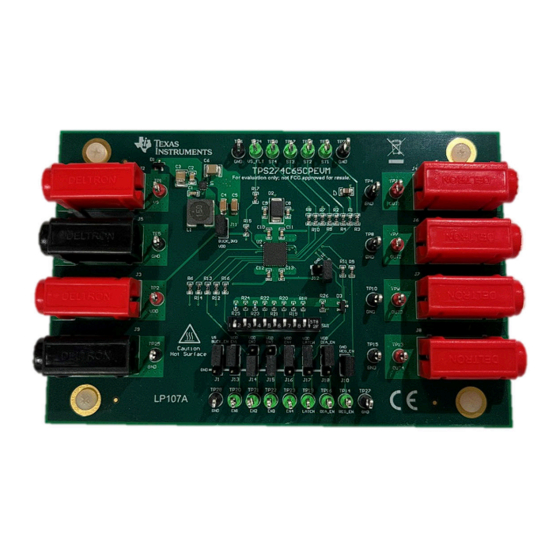
TPS274C65CP Evaluation Module
Description
The Texas Instruments TPS274C65CPEVM is an
evaluation module that is used to demonstrate and
showcase all of the features of the underlying
TPS274C65 industrial high side switch. This
evaluation board provides a seamless way to connect
a set of power supplies to the inputs of the
TPS274C65, connect loads to the output channels,
and switch on and off the device using the control
pins of the chip itself, and easily assert and deassert
logic signals by the use of a set of external
hardware jumpers.. An on-board 3.3-V buck-converter
is included on the EVM to allow for external VDD.
SLVUCS3 – OCTOBER 2023
Submit Document Feedback
Features
•
On-board 3.3-V buck-converter allowing for
external VDD and lower device Iq
•
Operating voltage 12 V-36 V
•
Programmable current limit with external resistor
•
Operating free-air temperature: –40 to 125°C
Applications
•
Industrial PLC systems
–
– IOLink ports
– Sensor supplies
Copyright © 2023 Texas Instruments Incorporated
Digital output modules
TPS274C65CP Evaluation Module
Description
1
Advertisement
Table of Contents

Related Manuals for Texas Instruments TPS274C65CP


Summary of Contents for Texas Instruments TPS274C65CP
- Page 1 Description EVM User's Guide: TPS274C65CPEVM TPS274C65CP Evaluation Module Description Features The Texas Instruments TPS274C65CPEVM is an • On-board 3.3-V buck-converter allowing for evaluation module that is used to demonstrate and external VDD and lower device Iq showcase all of the features of the underlying •...
-
Page 2: Kit Contents
The comprehensive fault reporting include a dedicated VS_FLT pin to indicate the VS undervoltage, and separate fault pin STx to indicate the faults happening in each channel. The TPS274C65CP is available in a small 6 mm × 6 mm QFN package with 0.5 mm pin pitch, which minimizes PCB footprint. - Page 3 Table 2-1 shows the relevant configuration jumpers of the TPS274C65CPEVM as well as the associated values. Please refer to the TPS274C65CP data sheet for detailed information on the functionality of each pin. Note If the ground network is used (J12 unpopulated), then an external VDD needs to be used at a voltage greater than 4 V due to the ground shift and minimum VDD undervoltage lockout threshold.
-
Page 4: Test Points
TP14 REG_EN Signal. TP16 DIA_EN Signal. TP19 Latch Signal. TP24 FAULT Signal. TP20 EN1 Signal. TP21 EN2 Signal. TP22 EN3 Signal. TP23 EN4 Signal. TPS274C65CP Evaluation Module SLVUCS3 – OCTOBER 2023 Submit Document Feedback Copyright © 2023 Texas Instruments Incorporated... - Page 5 Hardware Design Files 3 Hardware Design Files 3.1 Schematics Figure 3-1. TPS274C65CPEVM Schematic SLVUCS3 – OCTOBER 2023 TPS274C65CP Evaluation Module Submit Document Feedback Copyright © 2023 Texas Instruments Incorporated...
-
Page 6: Pcb Layouts
Hardware Design Files www.ti.com 3.2 PCB Layouts Figure 3-2. 3D Representation Figure 3-3. Top Layer TPS274C65CP Evaluation Module SLVUCS3 – OCTOBER 2023 Submit Document Feedback Copyright © 2023 Texas Instruments Incorporated... - Page 7 Hardware Design Files Figure 3-4. Ground Layer Figure 3-5. Power Layer SLVUCS3 – OCTOBER 2023 TPS274C65CP Evaluation Module Submit Document Feedback Copyright © 2023 Texas Instruments Incorporated...
- Page 8 Hardware Design Files www.ti.com Figure 3-6. Bottom Layer TPS274C65CP Evaluation Module SLVUCS3 – OCTOBER 2023 Submit Document Feedback Copyright © 2023 Texas Instruments Incorporated...
-
Page 9: Bill Of Materials (Bom)
Body 6.8x6.8mm ohm, SMD R1, R2, R7, R8, RES, 4.7 k, 5%, 0.1 W, AEC- 4.7k 0603 ERJ-3GEYJ472V Panasonic R15, R26 Q200 Grade 0, 0603 SLVUCS3 – OCTOBER 2023 TPS274C65CP Evaluation Module Submit Document Feedback Copyright © 2023 Texas Instruments Incorporated... - Page 10 LMR36503/06-Q1 Wide Input 60-V Synchronous, DC-DC RPE0009A LMR36506R3RPET Texas Instruments Buck Converter, RPE0009A (VQFN-9) 65-mΩ Quad-Channel Smart High-Side Switch with VQFN40 TPS274C65CPWRHAR Texas Instruments Diagnostics TPS274C65CP Evaluation Module SLVUCS3 – OCTOBER 2023 Submit Document Feedback Copyright © 2023 Texas Instruments Incorporated...
-
Page 11: Additional Information
Additional Information 4 Additional Information 4.1 Trademarks All trademarks are the property of their respective owners. SLVUCS3 – OCTOBER 2023 TPS274C65CP Evaluation Module Submit Document Feedback Copyright © 2023 Texas Instruments Incorporated... - Page 12 STANDARD TERMS FOR EVALUATION MODULES Delivery: TI delivers TI evaluation boards, kits, or modules, including any accompanying demonstration software, components, and/or documentation which may be provided together or separately (collectively, an “EVM” or “EVMs”) to the User (“User”) in accordance with the terms set forth herein.
- Page 13 www.ti.com Regulatory Notices: 3.1 United States 3.1.1 Notice applicable to EVMs not FCC-Approved: FCC NOTICE: This kit is designed to allow product developers to evaluate electronic components, circuitry, or software associated with the kit to determine whether to incorporate such items in a finished product and software developers to write software applications for use with the end product.
- Page 14 www.ti.com Concernant les EVMs avec antennes détachables Conformément à la réglementation d'Industrie Canada, le présent émetteur radio peut fonctionner avec une antenne d'un type et d'un gain maximal (ou inférieur) approuvé pour l'émetteur par Industrie Canada. Dans le but de réduire les risques de brouillage radioélectrique à...
- Page 15 www.ti.com EVM Use Restrictions and Warnings: 4.1 EVMS ARE NOT FOR USE IN FUNCTIONAL SAFETY AND/OR SAFETY CRITICAL EVALUATIONS, INCLUDING BUT NOT LIMITED TO EVALUATIONS OF LIFE SUPPORT APPLICATIONS. 4.2 User must read and apply the user guide and other available documentation provided by TI regarding the EVM prior to handling or using the EVM, including without limitation any warning or restriction notices.
- Page 16 Notwithstanding the foregoing, any judgment may be enforced in any United States or foreign court, and TI may seek injunctive relief in any United States or foreign court. Mailing Address: Texas Instruments, Post Office Box 655303, Dallas, Texas 75265 Copyright © 2023, Texas Instruments Incorporated...
- Page 17 TI products. TI’s provision of these resources does not expand or otherwise alter TI’s applicable warranties or warranty disclaimers for TI products. TI objects to and rejects any additional or different terms you may have proposed. IMPORTANT NOTICE Mailing Address: Texas Instruments, Post Office Box 655303, Dallas, Texas 75265 Copyright © 2023, Texas Instruments Incorporated...
Need help?
Do you have a question about the TPS274C65CP and is the answer not in the manual?
Questions and answers