Table of Contents
Advertisement
Advertisement
Table of Contents

Related Manuals for Atlas Copco G 2


Summary of Contents for Atlas Copco G 2
- Page 1 INSTRUCTION BOOK OIL-INJECTED ROTARY SCREW COMPRESSORS G 2, G 3, G 4, G 5...
- Page 3 Atlas Copco Oil-injected rotary screw compressors G 2, G 3, G 4, G 5 From following serial No. onwards: WUX 200 511 Instruction book Original instructions COPYRIGHT NOTICE Any unauthorized use or copying of the contents or any part thereof is prohibited.
-
Page 4: Table Of Contents
Instruction book Table of contents General description......................4 ...........................4 NTRODUCTION .........................8 PERATING PRINCIPLE ..........................11 ONTROL PANEL ........................12 LECTRICAL DIAGRAMS ......................13 ROTECTION OF THE COMPRESSOR ............................15 IR DRYER Installation........................16 ........................16 NSTALLATION PROPOSAL ........................18 IMENSION DRAWINGS ........................20 LECTRICAL CONNECTIONS ..........................20 ICTOGRAPHS Operating instructions.................... - Page 5 Instruction book ......................34 ISPOSAL OF USED MATERIAL Adjustments and servicing procedures..............35 ............................35 IR FILTER ............................36 OOLERS ..........................36 AFETY VALVE ........................37 ELTS MAINTENANCE Problem solving......................39 Technical data.......................42 ......................42 EADINGS ON CONTROL PANEL ........................43 LECTRIC CABLE SIZE ..................
-
Page 6: General Description
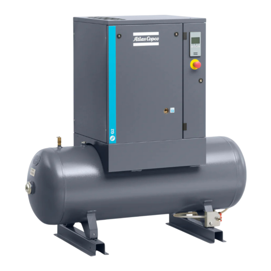
Instruction book General description Introduction Introduction G 2, G 3, G 4 and G 5 are air-cooled, single stage, oil-injected screw compressors, driven by an electric motor. The compressors are belt driven. The compressors are enclosed in sound insulating bodywork. - Page 7 Instruction book G 2 Pack, tank mounted Reference Description Control panel Air outlet Air receiver Condensate drain on air receiver 2920 7170 31...
- Page 8 Instruction book G 2 Full-Feature, tank mounted (front view) Reference Description Control panel Air receiver Dryer Manual condensate drain valve Oil separator tank Oil cooler Oil filter 2920 7170 31...
- Page 9 Instruction book G 2 Full-Feature, tank mounted (rear view) Reference Description Air outlet connection Air receiver Dryer Compressor element Oil separator Oil filter Air filter 2920 7170 31...
-
Page 10: Operating Principle
Instruction book Operating principle Pack units Flow diagram, tank mounted Pack units Air flow Air drawn in through air filter (AF) and open inlet valve (IV) is compressed in compressor element (E). Compressed air and oil flow into oil separator/tank (OT) where most of the oil is removed by centrifugal action. - Page 11 Instruction book A fan on the drive motor shaft provides air flow to cool the oil and the other components of the compressor. On tank mounted compressors, the air receiver is used as air cooler. The condensate is drained by means of a manual drain valve. Full-Feature Flow diagram, tank mounted Full-Feature units Air flow...
- Page 12 Instruction book Regulating system The main components of the regulating system are: • Pressure switch (PSR11) • Blow-off valve (Y1) The contacts of pressure switch (PSR11) open and close at preset pressures. During loaded operation, the contacts are closed: the motor is running. When the working pressure reaches the upper limit, the contacts of the pressure switch open: the motor stops.
-
Page 13: Control Panel
Instruction book Control panel Control panel Reference Designation Function Main switch To power the unit. Also used to stop the compressor in the event of an emergency and to reset the thermal overload of the electric motor by switching it to 0 and back to I. Also overload protection (only for IEC). -
Page 14: Electrical Diagrams
Instruction book Electrical diagrams Service diagram - IEC - 3 ph DOL 2920 7170 31... -
Page 15: Protection Of The Compressor
Instruction book Service diagram - IEC - 3 ph Y-D Text on image Main switch and fuses to be installed by customer. Protection of the compressor Safety valve on the compressor 2920 7170 31... - Page 16 Instruction book Safety valve on the air receiver (tank-mounted units) Reference Designation Function Motor overload relay To shut down the compressor in case the motor current See also section is too high. Electrical diagrams Temperature shut-down To shut down the compressor if the temperature at the See also section switch outlet of the compressor element is too high.
-
Page 17: Air Dryer
Instruction book Air dryer Air dryer (Full-Feature compressors) Wet compressed air (B) enters the dryer and flows through a heat exchanger (2) where refrigerant evaporates, withdrawing heat from the air. The cold air then flows through a condensate trap (1) which separates condensate from the air. The condensate is automatically drained and this is regulated by a timer. -
Page 18: Installation
Instruction book Installation Installation proposal Outdoor/altitude operation If the compressor is installed outdoors or if the ambient temperature can be below 0˚C (32˚F), precautions must be taken. In this case, and also if operating at high altitude, consult Atlas Copco. Moving/lifting Transport by a pallet truck To prevent a tank-mounted model from falling over during transport by a pallet truck:... - Page 19 Instruction book Installation proposal Installation proposal, tank mounted units Ref. Description/recommendation Isolating switch, compressor Isolating switch, dryer Front panel, compressor Dryer Minimum 1.5 m Space for maintenance, minimum 2 m Single-phase dryer supply Three-phase screw compressor supply The power cable should be protected so that it complies with local codes Step Action Install the compressor on a solid, level floor suitable for taking the weight.
-
Page 20: Dimension Drawings
Instruction book Step Action The pressure drop over the air delivery pipe can be calculated as follows: 1.85 Δp = (L x 450 x Q ) / (d x P), with d = Inner diameter of the pipe in mm Δp = Pressure drop in bar (recommended maximum: 0.1 bar (1.5 psi)) L = Length of the pipe in m P = Absolute pressure at the compressor outlet in bar... - Page 21 Instruction book Ref. Designation Condensate drain pipe, valve included Cooling air outlet Electrical cable entry Cooling air inlet Compressed air outlet Tank mounted Full—Feature units Ref. Designation Condensate drain pipe, valve included Cooling air outlet Electrical cable entry Cooling air inlet Compressed air outlet 2920 7170 31...
-
Page 22: Electrical Connections
Instruction book Electrical connections Always disconnect the power supply before working on the electrical circuit! General instructions Step Action Ensure that the supply voltage matches the voltage on the data plate. Install an isolating switch near the compressor. For Full-Feature compressors: fit an isolating switch near the dryer. Fit fuses in the incoming wiring. - Page 23 Instruction book Ref. Description Warning: moving parts Warning: rotating fan Drain the condensate daily and inspect the vessel yearly. Note down the inspection dates. Read the instruction manual Ref. Description Working pressure Hour meter Reset of temperature protection High temperature outlet of the compressor element Read instruction manual before carrying out maintenance or repair work Lightly oil gasket of oil filter, screw filter on and tighten by hand 2920 7170 31...
-
Page 24: Operating Instructions
Instruction book Operating instructions Initial start-up Safety The operator must apply all relevant Safety precautions. General preparation Air outlet valve Step Action Consult the installation instructions (see section Installation proposal). Check that the electrical connections correspond to the local codes. The installation must be earthed and protected against short circuits by fuses in all phases. - Page 25 Instruction book Lubrication Oil level sight glass (SG) Step Action If more than 3 months have passed between assembly and installation, be sure to lubricate the compressor before starting up: • Remove the front panel. • Unscrew the fixing bolts of the top panel and remove the panel. •...
-
Page 26: Starting
Instruction book Start-up Label on the top Step Action Check that all bodywork panels are fitted. Check that sheet (5) (explaining the procedure for checking the motor rotation direction) is affixed to the cooling air outlet of the compressor (grating on the compressor top). Consult section Dimension drawings. - Page 27 Instruction book Starting the air dyer Dryer on/off switch Switch on the voltage to the dryer and start it by moving switch (3) to position I. • Switch on the dryer before starting the compressor. • The dryer must remain switched on when the compressor is operating to ensure that the air piping remains condensate-free.
-
Page 28: Stopping
Instruction book Step Action Check the oil level sight glass (SG). The oil level should be in the middle. If it is below the minimum level, top up to the middle. Do not overfill. Switch on the voltage. Open air outlet valve (2). Move start/stop switch (1) to position I. -
Page 29: Taking Out Of Operation
Instruction book Step Action On Full-Feature units: move the dryer switch (2) to position 0. To stop the compressor, move start/stop switch (1) to position 0. Close the air outlet valve and switch off the voltage to the compressor. Open condensate drain valve (Dm) for a few seconds to drain any condensate and then close the valve. -
Page 30: Maintenance
When servicing, replace all removed gaskets, O-rings and washers. Intervals Carry out maintenance at the interval which comes first. The local Atlas Copco Customer Centre may overrule the maintenance schedule, especially the service intervals, depending on the environmental and working conditions of the compressor. -
Page 31: Drive Motor
Compressor data). Exposure of the compressor to external pollutants or operation at high humidity combined with low duty cycles may require a shorter oil exchange interval. Contact Atlas Copco if in doubt. Important • Always consult Atlas Copco if a service timer setting has to be changed. -
Page 32: Oil Specifications
Note: The presence of dust and/or high humidity may require a shorter exchange interval. Consult Atlas Copco. Atlas Copco's Roto-Inject Fluid Ndurance is a premium mineral oil based 4000 hours lubricant, specially developed for use in single stage oil-injected screw compressors running in mild conditions. -
Page 33: Oil, Filter And Oil Separator Change
If the compressor is exposed to external pollutants, is being used at high temperatures (oil temperature above 90˚C / 194˚F) or is being used under severe conditions, it is advisable to change the oil more frequently. Consult Atlas Copco. 2920 7170 31... - Page 34 Instruction book Step Action Run the compressor until warm. Stop the compressor, close the air outlet valve and switch off the voltage. Remove the front and top panels. Depressurize the compressor by unscrewing filler plug (8) one turn to permit any pressure in the system to escape.
-
Page 35: Pdx/Ddx Filter Change (Option)
Refit the filter bowl. Tighten oil filler plug (3). Close condensate drain valve (4) (tank mounted units). Storage after installation If the compressor is stored without running from time to time, consult Atlas Copco as protective measures may be necessary. 2920 7170 31... -
Page 36: Service Kits
Atlas Copco parts while keeping the maintenance budget low. Also a full range of extensively tested lubricants, suitable for your specific needs is available to keep the compressor in excellent condition. -
Page 37: Adjustments And Servicing Procedures
Instruction book Adjustments and servicing procedures Air filter Changing the air filter Air filter (1) Procedure: Step Action Stop the compressor, close the air outlet valve and switch off the voltage. Remove the front panel and the top panel of the compressor housing. Unscrew the filter cover (1) and remove the filter element. -
Page 38: Coolers
Instruction book Coolers Oil cooler Step Action Keep oil cooler (Co) clean to maintain the cooling efficiency. Stop the compressor, close the air outlet valve and switch off the voltage. Remove any dirt from the cooler with a fibre brush. Never use a wire brush or metal objects. Then clean using an air jet. -
Page 39: Belts Maintenance
Instruction book Oil filler plug Testing The valve can be tested on a separate compressed air line. Before removing the valve, stop the compressor (see section Stopping). On a Full-Feature unit also stop the dryer. Close the air outlet valve, switch off the voltage, open drain valves (4) (if applicable) and unscrew filler plug (3) one turn to permit any pressure in the system to escape. - Page 40 Instruction book Read the warning in section Preventive maintenance. Belt tensioning procedure Step Action Stop the compressor, close the air outlet valve and switch off the voltage. Full-Feature versions: also stop the dryer. Remove the front panel of the compressor housing. Remove the side, back and top panels of the compressor housing.
-
Page 41: Problem Solving
Instruction book Problem solving Main switch Oil filler plug Dryer on/off switch 2920 7170 31... - Page 42 Remedy No compressed air passes Pipes are frozen inside Hot-gas by-pass valve through the dryer malfunctioning; consult Atlas Copco Condensate in the piping Insufficient condensate drain Check the operation of timer (T) The dryer is working outside Check room temperature - air its rating temperature at dryer.
- Page 43 Instruction book Condition Fault Remedy The compressor head is very The dryer is working outside Check room temperature - air hot (above 55˚C / 131˚F) - its rating temperature at dryer. Clean the motor overload condenser and check operation of Insufficient refrigerant in dryer Have system checked for leaks or refilled The motor is humming but...
-
Page 44: Technical Data
Instruction book Technical data Readings on control panel Pressure gauge Hourmeter Dewpoint indicator Ref. Name Air outlet pressure Reading: Modulates between preset unloading/stopping pressure and loading pressure Dew point temperature Hour meter Reading: Total running time 2920 7170 31... -
Page 45: Electric Cable Size
Cable size (Hz) 400 - 3 1 mm 1 mm 1.5 mm 1.5 mm Settings for overload relay and fuses G 2 and G 3 Frequency Voltage (V) Overload Circuit breaker, G Overload Circuit breaker, G Circuit breaker, (Hz) relay (IG),... -
Page 46: Reference Conditions And Limitations
Instruction book Reference conditions and limitations Reference conditions Air inlet pressure (absolute) Air inlet temperature ˚C Relative humidity Working pressure bar(e) Compressor data Limitations Maximum working pressure bar(e) Compressor data Minimum working pressure bar(e) Minimum ambient temperature ˚C Compressor data 50 Hz 10 bar (under reference conditions) Compressor type Frequency... - Page 47 Instruction book Compressor type Sound pressure level (according dB(A) to ISO 2151 (2004)) 2920 7170 31...
-
Page 48: Instructions For Use
Instruction book Instructions for use Oil separator vessel The vessel can contain pressurized air. This can be potentially dangerous if the equipment is misused. This vessel must only be used as a compressed air/oil separator tank and must be operated within the limits specified on the data plate. No alterations must be made to this vessel by welding, drilling or other mechanical methods without the written permission of the manufacturer. -
Page 49: Guidelines For Inspection
Instruction book Guidelines for inspection Guidelines On the Declaration of Conformity / Declaration by the Manufacturer, the harmonised and/or other standards that have been used for the design are shown and/or referred to. The Declaration of Conformity / Declaration by the Manufacturer is part of the documentation that is supplied with this compressor. -
Page 50: Pressure Equipment Directives
Instruction book Pressure equipment directives Components subject to 97/23/EC Pressure Equipment Directive Components subject to 97/23/EC Pressure Equipment Directive greater than or equal to category Safety valves. See the spare parts book for part numbers. Overall rating The compressors conform to PED smaller than category I. 2920 7170 31... - Page 52 COMMITED TO SUSTAINABLE PRODUCTIVITY We stand by our responsibilities towards our customers, towards the environment and the people around us. We make performance stand the test of time. This is what we call — Sustainable Productivity. www.atlascopco.com...
Need help?
Do you have a question about the G 2 and is the answer not in the manual?
Questions and answers