Table of Contents
Advertisement
Quick Links
Advertisement
Table of Contents

Subscribe to Our Youtube Channel
Related Manuals for Atlas Copco G 18


Summary of Contents for Atlas Copco G 18
- Page 1 INSTRUCTION BOOK OIL-INJECTED ROTARY SCREW COMPRESSORS G 18, G 22, G 15L...
- Page 3 Atlas Copco Oil-injected rotary screw compressors G 18, G 22, G 15L Instruction book Original instructions COPYRIGHT NOTICE Any unauthorized use or copying of the contents or any part thereof is prohibited. This applies in particular to trademarks, model denominations, part numbers and drawings.
-
Page 4: Table Of Contents
Instruction book Table of contents Safety precautions......................5 ........................... 5 AFETY ICONS ......................5 ENERAL SAFETY PRECAUTIONS ................... 6 AFETY PRECAUTIONS DURING INSTALLATION ....................7 AFETY PRECAUTIONS DURING OPERATION ................8 AFETY PRECAUTIONS DURING MAINTENANCE OR REPAIR .......................10 ISMANTLING AND DISPOSAL General description...................... 11 ..........................11 NTRODUCTION ............................ - Page 5 Instruction book .....................36 CROLLING THROUGH ALL SCREENS 3.10 ......................37 ALLING UP RUNNING HOURS 3.11 ....................... 38 ALLING UP MOTOR STARTS 3.12 .......................38 ALLING UP MODULE HOURS 3.13 ......................39 ALLING UP LOADING HOURS 3.14 ..................... 39 ALLING UP LOAD SOLENOID VALVE 3.15 ..................
- Page 6 Instruction book ..........................60 IL SPECIFICATIONS ....................62 FILTER AND SEPARATOR CHANGE PDX/DDX )....................64 FILTER CHANGE OPTION ......................65 TORAGE AFTER INSTALLATION ..........................65 ERVICE KITS Adjustments and servicing procedures..............66 ............................66 IR FILTER ............................67 OOLERS ..........................67 AFETY VALVE ....................
-
Page 7: Safety Precautions
Instruction book Safety precautions Safety icons Explanation Danger to life Warning Important note General safety precautions 1. The operator must employ safe working practices and observe all related work safety requirements and regulations. 2. If any of the following statements does not comply with the applicable legislation, the stricter of the two shall apply. -
Page 8: Safety Precautions During Installation
Instruction book 9. If compressed air is used in the food industry and more specifically for direct food contact, it is recommended, for optimal safety, to use certified Class 0 compressors in combination with appropriate filtration depending on the application. Please contact your customer center for advice on specific filtration. -
Page 9: Safety Precautions During Operation
Instruction book 12. The electrical connections must correspond to the applicable codes. The machines must be earthed and protected against short circuits by fuses in all phases. A lockable power isolating switch must be installed near the compressor. 13. On machines with automatic start/stop system or if the automatic restart function after voltage failure is activated, a sign stating "This machine may start without warning"... -
Page 10: Safety Precautions During Maintenance Or Repair
Instruction book 6. Keep all bodywork doors shut during operation. The doors may be opened for short periods only, e.g. to carry out routine checks. Wear ear protectors when opening a door. On machines without bodywork, wear ear protection in the vicinity of the machine. 7. - Page 11 Instruction book 3. Use only genuine spare parts for maintenance or repair. The manufacturer will disclaim all damage or injuries caused by the use of non-genuine spare parts. 4. All maintenance work shall only be undertaken when the machine has cooled down. 5.
-
Page 12: Dismantling And Disposal
Instruction book Also consult following safety precautions: Safety precautions during installation Safety precautions during operation. These precautions apply to machinery processing or consuming air or inert gas. Processing of any other gas requires additional safety precautions typical to the application which are not included herein. Some precautions are general and cover several machine types and equipment;... -
Page 13: General Description
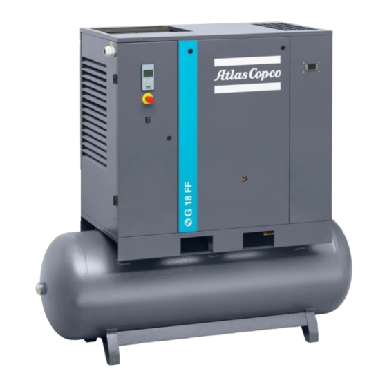
The compressor is installed directly on the floor. Tank-mounted model G 15L, G 18 and G 22 tank-mounted units are supplied with an air receiver of 500 l (132 US gal / 110 Imp gal / 17.5 cu.ft). Front view, G 18 Full-Feature tank-mounted... - Page 14 Designation Air outlet Air receiver Manual condensate drain Dryer Dewpoint indicator (only on Full-Feature units) Dryer main switch (only on Full-Feature units) Front open view, G 18 Full-Feature tank-mounted Reference Designation Oil cooler Oil filter Oil separator Oil separator tank...
- Page 15 Instruction book Rear open view, G 18 Full-Feature tank-mounted Reference Designation Air cooler Compressor element Air filter 2920 7119 21...
-
Page 16: Air Flow
Air flow Pack Air flow, G 15L, G 18 and G 22 Tank-mounted Pack Air drawn through filter (AF) and open inlet valve (IV) into compressor element (E) is compressed. Compressed air and oil flow into oil separator/tank (OT). The air is discharged via minimum pressure valve (Vp) and air cooler (Ca) towards the air outlet (AO). - Page 17 Instruction book Full-Feature Air flow, G 15L, G 18 and G 22 Tank-mounted Full-Feature Air drawn through filter (AF) and open inlet valve (IV) into compressor element (E) is compressed. Compressed air and oil flow into oil separator/tank (OT). The air is discharged via minimum pressure valve (Vp), air cooler (Ca) and air dryer (DR) towards the air outlet (AO).
-
Page 18: Oil System
Instruction book Oil system Oil system, G 15L, G 18 and G 22 Pack Oil system, G 15L, G 18 and G 22 Full-Feature Air pressure in the oil separator tank (OT) forces the oil from the tank to compressor element (E) via oil cooler (Co) and oil filter (OF). -
Page 19: Cooling System
Compressor data. Cooling system Cooling system, G 15L, G 18 and G 22 Pack The cooling system of the Pack version comprises oil cooler (Co) and fan (FN). The fan, mounted directly onto the motor shaft, generates the cooling air in order to cool the oil and the internal parts of the compressor. -
Page 20: Regulating System
Instruction book Cooling system, G 15L, G 18 and G 22 Full-Feature The cooling system of the Full-Feature version comprises oil cooler (Co), air cooler (Ca) and fan (FN). The dryer (DR) of Full-Feature versions has a separate cooling fan and an automatic condensate drain (see also section dryer). -
Page 21: Control Panel
The compressor will run unloaded (0% output). The G 15L, G 18 and G 22 are equipped with an intelligent controller that will stop the compressor after a variable period of unloaded operation using the following control algorithm: •... -
Page 22: Electrical System
Instruction book Control panel Control panel G 15L, G18 and G 22 Reference Designation Electric cabinet Elektronikon™ Base controller Emergency stop button Dryer Main Switch (Only on Full-Feature units) Electrical system Electrical components The electrical system comprises the following components: Electric cubicle IEC 2920 7119 21... - Page 23 Instruction book Electric cubicle cULus / cCSAus Reference Designation Primary fuse, transformer of the control circuit Phase sequence relay fuse F3-4-5-6 Fuses Primary fuse, transformer of the dryer Secondary fuse, transformer of the dryer Motor overload relay Auxiliary circuit relay Delta contactor Line contactor Dryer relay (only on Full-Feature)
-
Page 24: Protection Of The Compressor
Service diagram G 15L – G 18 – G 22 IEC 2205 0324 00 Service diagram G 15L – G 18 – G 22 cULus/ cCSAus The complete electrical diagram can be found in the electric cubicle. The complete electrical diagram can be found on the USB supplied with the machine. -
Page 25: Air Dryer
Instruction book Air dryer Air Dryer Wet compressed air enters the dryer and is further cooled by the outgoing, dried air (2). Moisture in the incoming air condenses. The air then flows through heat exchanger (1) where refrigerant evaporates, withdrawing heat from the air. The cold air then flows through condensate trap (4) which separates condensate from the air. -
Page 26: Controller
Instruction book Controller Controller Control panel Introduction In general, the controller has the following functions: • Controlling the compressor; • Protecting the compressor; • Monitoring service intervals; • Automatic restart after voltage failure (made inactive); Automatic control of the compressor The controller maintains the net pressure between programmable limits by automatically loading and unloading the compressor. -
Page 27: Control Panel
Instruction book shutdown warning temperature, this will be indicated on the controller display before the shutdown temperature is reached. Shutdown If the compressor element outlet temperature exceeds the programmed shutdown level or the overload relay of the main motor trips, the compressor will be stopped. This will be indicated on the display of the controller. -
Page 28: Icons Used On The Display
Instruction book Reference Designation Function LED, Voltage on Indicates that the voltage is switched on. Start/stop button Keep pressed for 3 seconds to start compressor. Press to stop compressor if running. Use this button to go to previous screen or to end the current action. -
Page 29: Main Screen
Instruction book Function Icon Description Service Service required Units Pressure unit (Mega Pascal) Pressure unit (pounds per square inch) Pressure unit (bar) Temperature unit (degree Centigrade) Temperature unit (degree Fahrenheit) Motor A time/delay parameter is displayed. NOTE: • x1000: ON if the displayed value is in thousands of •... -
Page 30: Main Function
Instruction book Main screen with pressure (stopped compressor) From the Main screen it is possible with up and down buttons (4-8) to change the view from pressure to temperature of the element outlet. Main screen with temperature (stopped compressor) Main function To switch on the compressor, press the start/stop button (3) for 3 seconds. - Page 31 Instruction book Screen with unloading compressor After the unload time has elapsed, the compressor is stopped and the controller goes back to main screen: Main screen with pressure (stopped compressor) To enter the main menu (starting from the Main screen), press the enter button (7) for 3 seconds. The main menu is shown: First screen of main menu It is possible to scroll in the menu with the up or down buttons (4-8).
-
Page 32: Shutdown Warning
Instruction book Emergency stop When the emergency push button is restored, reset the alarm by pressing the enter button (7) for 5 seconds. The following screen will appear: Alarm reset Shutdown warning Description A shutdown warning will appear in the event of: •... -
Page 33: Shutdown
Instruction book It remains possible to check the actual status of other parameters by pressing the enter button (7) for 3 seconds. Press button (3) to stop the compressor and wait until the compressor has stopped. The warning message will disappear as soon as the warning condition disappears. Shutdown Description The compressor will stop:... - Page 34 Instruction book Main screen with shutdown indication, element outlet temperature • The related pictograph will appear flashing. • Scroll Up or Down buttons (4-8) until the current element outlet temperature appears. Shutdown screen, element outlet temperature The screen shows that the temperature at the outlet of the compressor element is 117 ˚C. •...
- Page 35 Instruction book Example of error sensor Motor overload In the event of motor overload: • The compressor will stop. • Alarm LED (5) will flash. • The following screen will appear: Main screen with shutdown indication, motor overload • Contact your supplier for fault troubleshooting •...
-
Page 36: Service Warning
Instruction book Main screen with shutdown indication, phase sequence incorrect • Switch off the voltage, open the disconnector switch and reverse two phases of the supply cable. • Switch on the voltage and restart the compressor. The shutdown message will disappear automatically when the shutdown condition has disappeared. - Page 37 Instruction book Example of running hours screen The example screen shows that the service timer is at 2002 hours. Stop the compressor, switch off the voltage and carry out the required service actions. After servicing, reset the service timer. See section Calling up/resetting the service timer.
-
Page 38: Scrolling Through All Screens
Instruction book Scrolling through all screens Control panel General overview of the menu structure From the Main screen press the enter button (7) for 3 seconds to enter the Menu. You will find the following items: dAtA Data counters parameters. ProG Submenu of Regulation pressure, Timer, Display setting and Control setting. -
Page 39: Calling Up Running Hours
Instruction book Overview of the screens Menu item Submenu Digital input screen Designation <dAtA> <d.1> Running hours. (Data) <d.2> Motor starts. <d.3> Module hours. <d.4> Loading hours. <d.5> Load solenoid valve. <d.6> Service timer. <ProG> <rEG.P> <Pr.SL> Calling up or modifying pressure band (Programming) (Regulation selection. -
Page 40: Calling Up Motor Starts
Instruction book • Select <dAtA> and press Enter button (7) to enter the Data menu. • Scroll Up or Down buttons (4-8) until <d.1> and the motor stopped symbol is shown. • Press Enter button (7): the running hours are shown. The screen shows the unit used <x1000 hrs>... -
Page 41: Calling Up Loading Hours
Instruction book In the example shown, the screen shows the unit used <hrs> and the value <5000>: the controller module has been in service during 5000 hours. 3.13 Calling up loading hours Starting from the Main screen: • Press Enter button (7) for 3 seconds to enter the Main menu. •... -
Page 42: Calling Up/Resetting The Service Timer
Instruction book This screen shows the number of loading actions (x1 or - if <x1000> lights up - x1000). In the above example, the number of unload to load actions is 10100. 3.15 Calling up/resetting the service timer Starting from the Main screen: •... -
Page 43: Calling Up/Modifying Pressure Band Settings
Instruction book • Scroll Up or Down buttons (4-8) until <PrSL> is shown and then press Enter button (7). • Pressure band 1 (<SEL.1>) is shown. Scroll Up or Down buttons (4–8) to pressure band 2 (<SEL.2>). • Press Enter button (7) on the desired pressure band. 3.17 Calling up/modifying pressure band settings Starting from the Main screen: •... -
Page 44: Calling Up/Modifying Backlight Time
Instruction book Starting from the Main screen: • Press Enter button (7) for 3 seconds to enter the Main menu. • Select <ProG> and press Enter button (7) to enter the Programming menu. • Scroll Up or Down buttons (4-8) to <diSp> for display settings. •... -
Page 45: Keyboard Lock
Instruction book 3.22 Keyboard lock Keep both Up and Down buttons pressed for more than 3 seconds to lock or unlock the keyboard. • The display will show the label <Loc> blinking for 3 seconds if the keyboard has been locked. -
Page 46: Installation
Instruction book Installation Installation proposal Outdoor/altitude operation If the compressor is installed outdoors or if the ambient temperature can be below 0˚C (32˚F), precautions must be taken. In this case, and also if operating at high altitude, consult Atlas Copco. Moving/lifting Transport by a pallet truck For transport with a fork truck, use the openings in the frame. - Page 47 Instruction book Installation proposal Installation proposal, G 15L, G 18 and G 22 Ref. Action Install the compressor on a solid, level floor suitable for taking its weight. The recommended minimum distance between the top of the unit and the ceiling is 900 mm (35.1 in).
-
Page 48: Dimension Drawings
The dimension drawing can be found in the technical documentation supplied with the unit. Dimension drawing Model 9828 0837 16 G 15L, G 18, G 22 Pack, floor-mounted 9828 0837 17 G 15L, G 18, G 22 Pack, tank-mounted 9828 0837 52... -
Page 49: Electrical Connections
Instruction book Text on drawings Translation or explanation Dryer outlet cooling air Dryer outlet cooling air Electrical connections Always disconnect the power supply before working on the electrical circuit! General instructions Step Action Install an isolating (disconnector) switch near the compressor. Check the fuses and the setting of overload relay. - Page 50 Instruction book G 15L – G 22 200/230/460V 60Hz Modifications to the compressor cubicle: Step Action Adjust the motor overload (F21) setting. Control transformer (T1) – Move the primary connection from 230V to the desired voltage. Replace the control fuses (F1) 10.3 x 38mm with the ones provided (see further). Use 2A fuses for 460V or 5A for 200V On Full-Feature units, replace the power fuses (F7) with the CC type provided.
- Page 51 Instruction book Motor overload (F21) settings 15 kW 18 kW 22 kW 20 hp 25 hp 30 hp 200 V 41.2 49.6 58.6 230 V (Standard factory setting) 36.6 44.2 51.7 460 V 18.3 22.1 25.9 Control transformer (T1): Move the wire to the terminal marked with the desired voltage (200 V, 230 V or 460 V). Transformer T1 Fuses F1 –...
-
Page 52: Pictographs
Instruction book Move the wire to the terminal marked with the desired voltage (200 V, 230 V or 460 V). Transformer T2 Pictographs Ref. Description Working pressure Hour meter Dew point temperature Start Stop Warning: voltage Lightly oil gasket of oil filter, screw filter on and tighten by hand Warning: switch off voltage and depressurise compressor before carrying out maintenance work 2920 7119 21... -
Page 53: Operating Instructions
Instruction book Operating instructions Initial start-up Safety The operator must apply all relevant Safety precautions. General preparation Air outlet valve on air receiver Condensate drain 2920 7119 21... - Page 54 Instruction book Condensate drain valve on air receiver Step Action Consult the installation instructions (see Installation). Check that the electrical connections correspond to the local codes. The installation must be earthed and protected against short circuits by fuses in all phases. An isolating switch must be installed near the compressor.
-
Page 55: Starting
Instruction book Start-up Step Action Switch on the voltage. Press the start button for at least 3 seconds. If the motor rotation direction is correct, the compressor starts. If the rotation direction of the motor is incorrect, the compressor doesn’t start and the controller display will show an alarm. - Page 56 Instruction book Starting the compressor Position of oil sight glass and filler plug Control panel Step Action Before starting, check the oil level in accordance with step 5 of this table. Switch on the voltage. Open air outlet valve (2). Push the start button (6) and the motor starts running.
-
Page 57: Stopping
Instruction book Step Action In automatic operation, the regulator is automatically controlling the compressor, i.e. loading, unloading, stopping of the motors and restarting. Regularly check the working pressure and the dew point (Full-Feature units). Regularly check that condensate is drained (Da) during operation. Stopping Air outlet valve Condensate drain valve on air receiver... -
Page 58: Taking Out Of Operation
Instruction book Step Action Push the start/stop button (6) on the controller. The compressor will unload. When the unload time has elapsed, the compressor is stopped and the controller goes back to the main screen. To stop the compressor immediately in the event of an emergency, press button (S3). See section Control panel. - Page 59 Instruction book Oil filler plug This procedure should be carried out at the end of the compressor’s service life. Step Action Stop the compressor and close the air outlet valve (2). Switch off the voltage and disconnect the compressor from the mains. Depressurize the compressor by opening plug (3) one turn.
-
Page 60: Maintenance
When servicing, replace all removed gaskets, O-rings and washers. Intervals Carry out maintenance at the interval which comes first. The local Atlas Copco Customer Center may overrule the maintenance schedule, especially the service intervals, depending on the environmental and working conditions of the compressor. -
Page 61: Drive Motor
Compressor data). Exposure of the compressor to external pollutants or operation at high humidity combined with low duty cycles may require a shorter oil exchange interval. Contact Atlas Copco if in doubt. Important • Always consult Atlas Copco if a service timer setting has to be changed. -
Page 62: Oil Specifications
Note: The presence of dust and/or high humidity may require a shorter exchange interval. Consult Atlas Copco. Atlas Copco's Roto-Inject Fluid Ndurance is a premium mineral oil based 4000 hours lubricant, specially developed for use in single stage oil-injected screw compressors running in mild conditions. - Page 63 Note: The presence of dust and/or high humidity may require a shorter exchange interval. Consult Atlas Copco. Atlas Copco's Roto Synthetic Fluid XTEND DUTY is a high quality synthetic 8000 hours lubricant for oil injected screw compressors which keeps the compressor in excellent condition. Because of its excellent oxidation stability, Roto Synthetic Fluid XTEND DUTY can be used for compressors operating at ambient temperatures between 0 ˚C (32 ˚F) and 46 ˚C (115 ˚F).
-
Page 64: Oil, Filter And Separator Change
Consult Atlas Copco. Special oil, delivered as an option. Atlas Copco's Roto-Foodgrade Fluid is a unique high quality synthetic lubricant, specially created for oil injected screw compressors that provide air for the food industry. This lubricant keeps the compressor in excellent condition. Roto-Foodgrade Fluid can be used for compressors operating at ambient temperatures between 0 ˚C (32 ˚F) and 40 ˚C (104 ˚F). - Page 65 Instruction book Step Action Run the compressor until warm. Stop the compressor, close the air outlet valve and switch off the voltage. See Stopping. Depressurize the air receiver by opening drain valve (8). Depressurize the compressor by unscrewing filler plug (2) one turn to permit any pressure in the system to escape.
-
Page 66: Pdx/Ddx Filter Change (Option)
Instruction book Step Action Check the oil level through the sight-glass (4). If the oil level is lower than the minimum level, add oil until the maximum level is reached. Never mix oils of different brands or types. A label, indicating the type of oil filled ex- factory, is attached on the air receiver/oil tank. -
Page 67: Storage After Installation
Refit the filter bowl. Tighten oil filler plug (3). Close condensate drain valve (4). Storage after installation If the compressor is stored without running from time to time, consult Atlas Copco as protective measures may be necessary. Service kits Service kits For overhauling and for preventive maintenance, a wide range of service kits is available. -
Page 68: Adjustments And Servicing Procedures
Instruction book Adjustments and servicing procedures Air filter Changing the air filter Air filter Procedure: Step Action Stop the compressor, close the air outlet valve and switch off the voltage. Open the isolating (disconnector) switch (IG). Remove the front panel and the top panel of the compressor housing. Unscrew the filter cover (AF) and remove the filter element. -
Page 69: Coolers
Instruction book Coolers Step Action Keep the oil cooler (Co) clean to maintain the cooling efficiency. Also keep the cooler (Ca) clean to maintain the cooling efficiency. Stop the compressor, close the air outlet valve and switch off the voltage. Remove any dirt from the oil cooler (Co) with a fibre brush. -
Page 70: Belt Set Exchange And Tensioning
Instruction book Oil filler plug Testing The valve can be tested on a separate compressed air line. Before removing the safety valve, stop the compressor (see section Stopping), close the air outlet valve, switch off the voltage, open the isolating (disconnector) switch (IG), open drain valves (4) (tank-mounted units) and the manual drain valve (5) (if fitted - on floor-mounted units) and unscrew filler plug (3) one turn to permit any pressure in the system to escape. - Page 71 Instruction book Checking the belt tension Step Action Stop the compressor, close the air outlet valve and switch off the voltage. Open the isolating (disconnector) switch (IG). Remove the front door and the internal panel. The force and deflection varies with the power of the unit, and with the total running hours of the belt.
- Page 72 Instruction book Step Action The force and deflection varies with the power of the unit, and with the total running hours of the belt. The values to be measured are indicated with a label (1) on the frame: Retighten bolts (2). Refit the bodywork panels.
-
Page 73: Dryer Maintenance Instructions
Action The belts (3) must be replaced as a set, even if only one of the belts is worn. Only use genuine Atlas Copco belts. Stop the compressor, close the air outlet valve and switch off the voltage. Open the isolating (disconnector) switch (IG). - Page 74 Instruction book General For all references see section Introduction. The following remarks should be kept in mind: • Keep the dryer clean. • Brush or blow off the finned surface of condenser monthly. • Switch off the voltage and close the air outlet valve. •...
-
Page 75: Problem Solving
Instruction book Problem solving Control panel Air outlet valve Oil filler plug 2920 7119 21... - Page 76 Instruction book Condensate drain valve on air receiver Attention Use only authorized parts. Any damage or malfunction caused by the use of unauthorized parts is not covered by Warranty or Product Liability. Apply all relevant Safety precautions during maintenance or repair.
- Page 77 Avoid recirculation of cooling air. If installed, check capacity of compressor room fan Oil level too low Check and correct as necessary Cooler clogged Clean cooler Compressor element (E) out of Consult Atlas Copco order 2920 7119 21...
-
Page 78: Technical Data
Instruction book Technical data Electric cable size Attention The voltage on the compressor terminals must not deviate more than 10% from the nominal voltage. It is however highly recommended to keep the voltage drop over the supply cables at nominal current below 5% of the nominal voltage. If cables are grouped together with other power cables, it may be necessary to use cables of a larger size than those calculated for the standard operating conditions. - Page 79 • If the local conditions are more severe then the described standard conditions, the cables for worst case conditions should be used. Recommended cable size Pack version – PVC 70 °C / XLPE-EPR 90 °C G 15L G 18 G 22 Frequency Voltage Cable size...
-
Page 80: Settings For Overload Relay And Fuses
Instruction book G 15L G 18 G 22 Frequency Voltage Cable size Cable size Cable size (Hz) 50 mm / 25 mm 50 mm / 35 mm 70 mm / 35 mm 16 mm / 10 mm 25 mm / 16 mm... - Page 81 Instruction book Frequency Voltage (V) G 15L G 18 G 22 (Hz) CSA/UL Overload FU Main Overload FU Main Overload FU Main relay FM1 fuses relay FM1 fuses relay FM1 fuses (A) (class J (A) (class J (A) (class J...
-
Page 82: Reference Conditions And Limitations
Nominal working pressure psig Set-point, thermostatic valve ˚C Set-point, thermostatic valve ˚F 15.6 15.6 15.6 15.6 15.6 15.6 15.6 G 18 Compressor type Frequency Maximum (unloading) pressure UL units 10.8 12.6 7.50 10 Maximum (unloading) pressure UL units psig Nominal working pressure 10.3 12.1 7.0... - Page 83 Instruction book Compressor type Nominal working pressure psig Set-point, thermostatic valve ˚C Set-point, thermostatic valve ˚F 15.6 15.6 15.6 15.6 15.6 15.6 15.6 G 22 Compressor type Frequency Maximum (unloading) pressure UL units 10.8 12.6 7.50 10 Maximum (unloading) pressure UL units psig Nominal working pressure 10.3 12.1 7.0...
-
Page 84: Instructions For Use
Instruction book Instructions for use Oil separator vessel The vessel can contain pressurized air. This can be potentially dangerous if the equipment is misused. This vessel must only be used as a compressed air/oil separator tank and must be operated within the limits specified on the data plate. No alterations must be made to this vessel by welding, drilling or other mechanical methods without the written permission of the manufacturer. -
Page 85: Guidelines For Inspection
Instruction book Guidelines for inspection Guidelines On the Declaration of Conformity / Declaration by the Manufacturer, the harmonised and/or other standards that have been used for the design are shown and/or referred to. The Declaration of Conformity / Declaration by the Manufacturer is part of the documentation that is supplied with this compressor. - Page 88 COMMITTED TO SUSTAINABLE PRODUCTIVITY We stand by our responsibilities towards our customers, towards the environment and the people around us. We make performance stand the test of time. This is what we call — Sustainable Productivity. www.atlascopco.com...
Need help?
Do you have a question about the G 18 and is the answer not in the manual?
Questions and answers
какое колво воздуха необходимо для воздушного охлаждения G15LP ростов на дону