Table of Contents
Advertisement
Quick Links
Advertisement
Table of Contents
Troubleshooting

Subscribe to Our Youtube Channel
Related Manuals for AEMC instruments 6536


Summary of Contents for AEMC instruments 6536
- Page 1 User Manual ENGLISH Megohmmeter Model 6536 MEGOHMMETERS WITH AEMC INSTRUMENTS ®...
- Page 2 Copyright Chauvin Arnoux , Inc. d.b.a. AEMC Instruments. All rights reserved. © ® ® No part of this documentation may be reproduced in any form or by any means (including electronic storage and retrieval or translation into any other language) without prior agreement and written consent from Chauvin Arnoux , Inc., as governed by United States and International copyright laws.
- Page 3 For recalibration, please use our calibration services. Refer to our repair and calibration section at www.aemc.com/calibration. Serial #: Catalog #: 2155.56 Model #: 6536 Please fill in the appropriate date as indicated: Date Received: Date Calibration Due: Chauvin Arnoux , Inc. ®...
-
Page 4: Table Of Contents
TABLE OF CONTENTS 1. INTRODUCTION ..............6 1.1 PRECAUTIONS FOR USE ............8 1.2 RECEIVING YOUR SHIPMENT ..........9 1.3 ORDERING INFORMATION: ............ 9 Shipping Contents: ..............9 1.3.1 Accessories ..............10 1.3.2 Replacement Parts ............10 2. PRODUCT FEATURES ............. 11 2.1 DESCRIPTION ................. - Page 5 3.2.4 Resistance Measurement ..........28 3.2.5 Floor Resistance Testing ..........29 3.2.5.1 Setup ................. 30 3.2.5.2 Test Procedure............30 3.2.5.3 Measurement Results ..........31 4. SPECIFICATIONS ............. 32 4.1 GENERAL REFERENCE CONDITIONS ........ 32 4.2 ELECTRICAL SPECIFICATIONS ........... 32 4.2.1 Voltage Measurement ............32 4.2.2 Insulation Measurement ...........
-
Page 6: Introduction
1. INTRODUCTION Thank you for purchasing an AEMC Instruments Megohmmeter Model 6536. ® For the best results from your instrument and for your safety, you must read the enclosed operating instructions carefully and comply with the precautions for use. Only qualified and trained operators should use this product.. - Page 7 CAT III: Corresponds to measurements performed in the building installation at the distribution level. Example: hardwired equipment in fixed installation and circuit breakers. CAT II: Corresponds to measurements performed on circuits directly connected to the electrical distribution system. Example: measurements on household appliances and portable tools. Megohmmeter Model 6536...
-
Page 8: Precautions For Use
■ Before removing the battery compartment cover, ensure all measurement leads and accessories are disconnected. Replace all batteries at once. Use alkaline batteries. ■ Use personal protection equipment where appropriate. ■ All troubleshooting and metrological checks must be done by competent, accredited personnel. Megohmmeter Model 6536... -
Page 9: Receiving Your Shipment
Save the damaged packing container to substantiate your claim. 1.3 ORDERING INFORMATION: Megohmmeter Model 6536 ..............Cat. #2155.56 Megohmmeter Model 6536 ESD Floor Kit ........Cat. #2155.57 Shipping Contents: (1) Soft Carrying Pouch - Cat. #2119.02 Megohmmeter Model 6536 7.75 x 9.25 x 2.75 in... -
Page 10: Accessories
Weights - Set of 2, 5 lbs each with conductive rubber bottom pad (RoHS) ................Cat. #2155.76 Adapter - 4 mm non-insulated for safety leads (Replacement for ESD Floor Kit)............Cat. #1017.45 Order Accessories and Replacement Parts Directly Online Check our Storefront at www.aemc.com/store for availability Megohmmeter Model 6536... -
Page 11: Product Features
■ Resistance measurement ■ Programmable alarms The Model 6536 is also available as a floor resistance testing kit (see § 3.2.5) for testing both point-to-ground and point-to-point electrostatic discharge (ESD). In addition to the instrument, the kit contains (2) 5 lb (2.3 kg) floor weights (also referred to as NFPA probes) that are in compliance with EOS/ESD 11.11... -
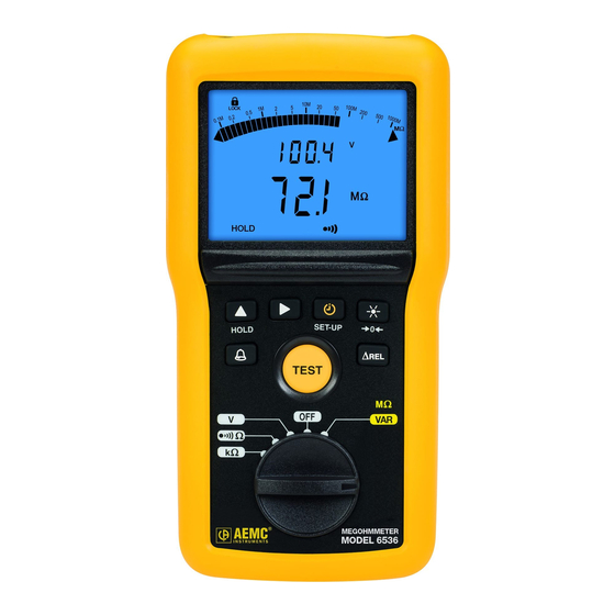
Page 12: Front Of Instrument
1. Input terminals 2. Blue backlit LCD 3. Six function buttons (see § 2.5 ) 4. TEST button to start insulation measurements (see § 3.2.2.1) 5. Five-position rotary switch to choose the function or to turn the instrument Megohmmeter Model 6536... -
Page 13: Back Of Instrument
2.3 BACK OF INSTRUMENT Figure 2 1. Captive quarter-turn screw 2. Battery compartment cover 3. Mounting magnets, molded into instrument case 4. Non-skid pads 5. Stand Megohmmeter Model 6536... -
Page 14: Terminals
Modify the display and program the durations of insulation ■ measurements (§ 3.2.2.2). ■ Choose the continuity test current (§ 3.2.3). ■ Program the alarm thresholds (§ 3.1.2). Displays the difference between the present measurement and a ∆Rel stored reference measurement (§ 3.1.3). Megohmmeter Model 6536... -
Page 15: Lcd Display
4. Icons/indicators When the measured value is below the minimum, the instrument displays When measuring voltage, if the reading falls outside the range defined by the positive and negative limits, the instrument displays OL or – OL. Megohmmeter Model 6536... -
Page 16: Operation
2. Press to change the setting to On. press 3. Press to validate the change. on symbol appears on the display when you exit Set-Up. Note that this setting reverts to OFF when you turn OFF the instrument. Megohmmeter Model 6536... -
Page 17: Alarms
The symbol appears on the LCD, along with the threshold value. TEST < ALARM To turn OFF the alarm buzzer while it is sounding, press the HOLD button. To deactivate an active alarm function, press the button. Megohmmeter Model 6536... -
Page 18: Setting An Alarm Threshold
5. When finished setting the threshold, press the ► button to validate the setting. 3.1.2.3 Viewing Alarms When the measurement is below a low alarm threshold or above a high alarm threshold, the instrument emits a continuous audible signal and the LCD indicates the threshold crossed: < ALARM Megohmmeter Model 6536... -
Page 19: Rel Function
) and will be stored and subtracted from subsequent measurement values (R ). The ∆REL symbol meas appears on the LCD while this function is activated. If the measured value is less than the stored value, the display becomes negative. Megohmmeter Model 6536... -
Page 20: Hold Function
To unfreeze the display, press the HOLD button again. 3.1.5 Backlighting Pressing the button turns ON backlighting for the LCD. To switch it OFF, press the button again. Otherwise, backlighting goes OFF automatically at the end of one minute. Megohmmeter Model 6536... -
Page 21: Standby Mode
(such as an electrical outlet) before measuring unknown voltages. 1. Set the switch to V or MΩ VAR. Ω Ω Ω 2. Using the leads, connect the system to be tested to the instrument’s terminals. Megohmmeter Model 6536... -
Page 22: Insulation Measurement
You can change this by pressing the ▲ key. Then use the ► and ▲ keys to navigate to and change the remaining digits. Allowable test voltages are 10 V through 100 V. When finished, press ► to validate the change. Megohmmeter Model 6536... - Page 23 7. At the end of the measurement, release the TEST button. The instrument stops generating the test voltage and discharges the device being tested. symbol is displayed until the voltage on the system under test has fallen below 70 V. Megohmmeter Model 6536...
-
Page 24: Test Button Operation
button to enter edit mode. When the first digit blinks, you can change it using the button. Press to go to the next digit and to change it. Then press to validate. press Exits timed test mode. Megohmmeter Model 6536... -
Page 25: Remote Control Probe (Optional)
The optional remote control probe is used to trigger the measurement using the TEST button on the probe. To use this accessory, refer to its separate operating instructions. When the probe is connected, the symbol is displayed on the instrument’s LCD. Megohmmeter Model 6536... -
Page 26: Continuity Measurement
The instrument reports that the compensation must be redone by displaying a blinking symbol. To remove the compensation of the leads, leave the leads open and press the button for >2 seconds. The LCD displays the resistance of the leads and symbol goes off. Megohmmeter Model 6536... -
Page 27: Continuity Measuring
To obtain a continuity value per standard IEC 61557: 1. Take a measurement at 200 mA and note its value, R1. 2. Reverse the leads and note the value R2. 3. Calculate the mean: Megohmmeter Model 6536... -
Page 28: Resistance Measurement
Resistance measurements are made with a low current. kΩ 1. Set the rotary switch to Ω Ω Ω 2. Connect the system to be tested to the instrument. The device to be tested must be powered down. 3. The instrument displays the results. Megohmmeter Model 6536... -
Page 29: Floor Resistance Testing
Electrostatic voltage must be less than +/-100 V. The Model 6536 can be purchased as part of a kit specifically designed for testing floor resistance in areas where electrostatic discharge is a concern, such as computer rooms, electronic assembly rooms, and hospitals. -
Page 30: Setup
3. Unless otherwise specified, make five measurements on each floor section with the weights at different locations for each measurement, and record the value to two significant figures (see Figure 5 below). Table Top Electrodes 36 " > 700V 600V CAT IV Figure 5 Megohmmeter Model 6536... -
Page 31: Measurement Results
5. When finished, turn off the Model 6536 and return it to the case. If the resistance changes with time during a measurement, the value observed after about 5 seconds should be considered the measured value. -
Page 32: Specifications
Input impedance 400 kΩ Frequency ranges DC and 15.3 at 800 Hz 4.2.2 Insulation Measurement Specific reference condition: Capacitance in parallel on resistance = null. Test Voltage (V (10 to 100) V /5) kΩ to (V /5) GΩ Megohmmeter Model 6536... - Page 33 25 V, the discharge time is < 2 s/µF. Test Current Maximum test current: 2 mA (0.01 to .99) (40.0 to 399.9) (0.400 to 2.000) Measurement Range µA µA Resolution 10 nA 100 nA 1 µA Accuracy ± (10 % R + 3 ct) Megohmmeter Model 6536...
-
Page 34: Continuity Measurement
200 mA range: 200 mA (0 mA + 20 mA) 20 mA range: 20 mA ± 5 mA Measurement Range (0 to 250) mA Resolution 1 mA Accuracy ± (2 % + 2 ct) Compensation of the Leads: (0 to 9.99) Ω Megohmmeter Model 6536... -
Page 35: Resistance Measurement
(15.3 to 800) Hz 2 % R + 1 ct Supply voltage (6.6 to 9.6) V V, F 0.1 % R + 2 ct Common mode (0 to 600) V 50 dB 40d B rejection in AC 50/60 Hz Megohmmeter Model 6536... -
Page 36: Insulation Measurement
= 50 V (0 to 1) µF 6 % R + 2 ct 10 % R + 2 ct ≤ 5 GΩ Common mode (0 to 600) Vac 50 dB 40 dB rejection in AC 50/60 Hz Megohmmeter Model 6536... -
Page 37: Resistance And Continuity Measurement
A = intrinsic uncertainty = influence of the reference position ± 90 ° = influence of the supply voltage within the limits indicated by the manufacturer = influence of the temperature between (0 and 35) °C (32 and 95) °F Megohmmeter Model 6536... -
Page 38: Power Supply
4.7 SAFETY STANDARDS Safety according to: EN 61010 Insulation Class: 2 Pollution Degree: 2 Overvoltage Category: 600 V CAT IV Immunity according to: EN 61326 Emission according to: EN 61326 Specifications are subject to change without notice. Megohmmeter Model 6536... -
Page 39: Maintenance & Troubleshooting
At start-up, the instrument displays the remaining battery life: G VHz If the battery voltage is too low to ensure correct operation of the instrument, a “low battery” message appears on the LCD and the symbol blinks: Megohmmeter Model 6536... - Page 40 1. Place the new batteries in the compartment, ensuring that each battery’s polarity is correct. 2. Put the battery compartment cover in place and screw in the quarter-turn screw. Megohmmeter Model 6536...
-
Page 41: Troubleshooting
If during a continuity or resistance measurement the instrument detects an external voltage in excess of 15 V (AC or DC), it interrupts the measurement and displays the screen show to the left. You must eliminate the voltage to resume the measurement. Megohmmeter Model 6536... -
Page 42: Resetting The Instrument
If you are experiencing any technical problems or require any assistance with the proper operation or application of your instrument, please call, e-mail or fax our technical support team: Chauvin Arnoux , Inc. d.b.a. AEMC Instruments ® ® Phone: (800) 343-1391 (Ext. 351) Fax: (603) 742-2346 E-mail: techsupport@aemc.com www.aemc.com Megohmmeter Model 6536... -
Page 43: Limited Warranty
(800) 945-2362 (Ext. 360) (603) 749-6434 (Ext. 360) Fax: (603) 742-2346 E-mail: repair@aemc.com Caution: To protect yourself against in-transit loss, we recommend that you insure your returned material. NOTE: You must obtain a CSA# before returning any instrument. Megohmmeter Model 6536... - Page 44 07/23 99-MAN 100431 v12 AEMC Instruments ® 15 Faraday Drive • Dover, NH 03820 USA Phone: (603) 749-6434 • (800) 343-1391 • Fax: (603) 742-2346 www.aemc.com © 2013 Chauvin Arnoux , Inc. d.b.a. AEMC Instruments. All Rights Reserved. ® ®...
Need help?
Do you have a question about the 6536 and is the answer not in the manual?
Questions and answers