
Related Manuals for AEMC instruments 6526


Summary of Contents for AEMC instruments 6526
- Page 1 User Manual ENGLISH Megohmmeter Models 6526 & 6534 MEGOHMMETERS WITH AEMC INSTRUMENTS ®...
- Page 2 Copyright Chauvin Arnoux , Inc. d.b.a. AEMC Instruments. All rights reserved. © ® ® No part of this documentation may be reproduced in any form or by any means (including electronic storage and retrieval or translation into any other language) without prior agreement and written consent from Chauvin Arnoux , Inc., as governed by United States and International copyright laws.
- Page 3 Refer to our repair and calibration section at www.aemc.com. Serial #: Catalog #: 2155.53 / 2155.55 Model #: 6526 / 6534 Please fill in the appropriate date as indicated: Date Received: Date Calibration Due: Chauvin Arnoux , Inc.
-
Page 4: Table Of Contents
2.2.2 Insulation Measurement ............23 2.2.2.1 TEST Button Operation ............25 2.2.2.2 Timed Tests................25 2.2.2.3 Remote Control Probe (Optional) ..........27 2.2.3 Continuity Measurement ............27 2.2.3.1 Lead Compensation ...............28 2.2.3.2 Continuity Measuring .............28 2.2.4 Resistance Measurement ............30 2.2.5 Capacitance Measurement (Model 6526) ......30... - Page 5 3.2.2 Frequency Measurement............34 3.2.3 Insulation Measurement ............35 3.2.4 Continuity Measurement ............37 3.2.5 Resistance Measurement ............37 3.2.6 Capacitance Measurement (Model 6526) ......37 3.2.7 Timer ..................38 3.2.8 Storage Memory ..............38 3.2.9 Bluetooth ................38 3.3 OPERATING ENVIRONMENT ...........38 3.3.1 Voltage Measurement ............
- Page 6 5.2.1.1 Voltage Present Before an Insulation Measurement ....48 5.2.1.2 Range Exceeded During an Insulation Measurement ...48 5.2.1.3 Voltage Present During a Continuity, Resistance, or Capacitance Measurement (Model 6526) ..........48 5.2.1.4 Memory Full ................49 5.2.2 Resetting the Instrument ............49 5.3 REPAIR AND CALIBRATION ..........49 5.4 TECHNICAL ASSISTANCE ..........50...
-
Page 7: Introduction
Example: hardwired equipment in fixed installation and circuit breakers. CAT II corresponds to measurements performed on circuits directly connected to the electrical distribution system. Example: measurements on household appliances and portable tools. Megohmmeter Models 6526 & 6534 - User Manual... -
Page 8: Precautions For Use
Replace all batteries at once. Use alkaline batteries. Use personal protection equipment where appropriate. ■ All troubleshooting and metrological checks must be done by competent, ■ accredited personnel. Megohmmeter Models 6526 & 6534 - User Manuall... -
Page 9: Receiving Your Shipment
Save the damaged packing container to substantiate your claim. Megohmmeter Models 6526 & 6534 - User Manual... -
Page 10: Ordering Information
Clip - Safety Alligator - Red (1000 V CAT IV, 15 A, UL V2) ..Cat. #5100.00 Order Accessories and Replacement Parts Directly Online Check our Storefront at www.aemc.com/store for availability Dataview Software Updates are Available at www.aemc.com ® Megohmmeter Models 6526 & 6534 - User Manuall... -
Page 11: Description
1.4 DESCRIPTION The Megohmmeters Models 6526 and 6534 are portable measuring instruments with digital displays. They are powered by batteries. These instruments can check the safety of electrical installations. For example, they can be used to test new installations before they are powered up, check an existing installation in a power-off condition, or troubleshoot an installation. -
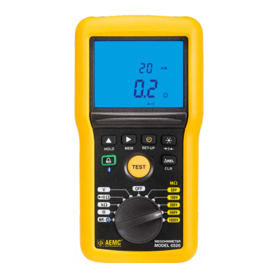
Page 12: Model 6526 (Front)
2. Blue backlit LCD 3. Six function buttons (see § 1.7) 4. TEST button to start insulation measurements (see § 2.2.2.1) 5. Eleven-position rotary switch to choose the function or to turn the instrument OFF Megohmmeter Models 6526 & 6534 - User Manuall... -
Page 13: Model 6534 (Front)
2. Blue backlit LCD 3. Six function buttons (see § 1.7) 4. TEST button to start insulation measurements (see § 2.2.2.1) 5. Ten-position rotary switch to choose the function or to turn the instrument Megohmmeter Models 6526 & 6534 - User Manual... -
Page 14: Back Of Instrument
1.5 BACK OF INSTRUMENT Figure 3 1. Captive quarter-turn screw 2. Battery compartment cover 3. Mounting magnets, moulded into instrument case 4. Non-skid pads 5. Stand Megohmmeter Models 6526 & 6534 - User Manuall... -
Page 15: Terminals
Program the alarm thresholds (§ 2.1.3). ■ Displays the difference between the present measurement and a stored ∆Rel reference measurement (§ 2.1.4). Records measurements (§ 2.3). Erase recorded measurements (§ 2.3.3). Enable Bluetooth wireless communication (§ 2.1.2). Megohmmeter Models 6526 & 6534 - User Manual... -
Page 16: Lcd Display
When the measured value is below the minimum, the instrument displays - - - - . When measuring voltage, if the reading falls outside the range defined by the positive and negative limits, the instrument displays OL or – OL. Megohmmeter Models 6526 & 6534 - User Manuall... -
Page 17: Operation
3. Press to validate the change. symbol appears on the display when you exit Set-Up. Note that this setting reverts to OFF when you turn OFF the instrument. press on Displays the instrument model number. Megohmmeter Models 6526 & 6534 - User Manual... -
Page 18: Bluetooth
< ALARM To turn OFF the alarm buzzer while it is sounding, press the HOLD button. To deactivate an active alarm function, press the button. Megohmmeter Models 6526 & 6534 - User Manuall... -
Page 19: Setting An Alarm Threshold
When the measurement is below a low alarm threshold or above a high alarm threshold, the instrument emits a continuous audible signal and the LCD indicates the threshold crossed: > < ALARM ALARM Megohmmeter Models 6526 & 6534 - User Manual... -
Page 20: Rel Function
If the measured value is less than the stored value, the display becomes negative. You can display the difference as a percentage of the reference ) by pressing the button until the % sign appears: Megohmmeter Models 6526 & 6534 - User Manuall... -
Page 21: Hold Function
Automatic switching to standby is disabled via the SET-UP button (see § 2.1.1). 2.2 TAKING MEASUREMENTS 2.2.1 Voltage Measurement NOTE: To ensure proper and accurate operation of the instrument, we recommend measuring a known voltage (such as an electrical outlet) before measuring unknown voltages. Megohmmeter Models 6526 & 6534 - User Manual... - Page 22 2. Using the leads, connect the system to be tested to the instrument's terminals. The instrument displays the voltage on the terminals. It detects whether the voltage is AC or DC; and (for Model 6526) if it is AC, displays its frequency. Megohmmeter Models 6526 & 6534 - User Manuall...
-
Page 23: Insulation Measurement
1. Set the rotary switch to one of the MΩ positions. The test voltage depends on the voltage of the installation to be tested. Ω Ω 100V Ω 250V 500V 1000V MR - Megohmmeter Models 6526 & 6534 - User Manual... - Page 24 6. At the end of the measurement, release the TEST button. The instrument stops generating the test voltage and discharges the device being tested. symbol is displayed until the voltage on the system under test has fallen below 70 V. Megohmmeter Models 6526 & 6534 - User Manuall...
-
Page 25: Test Button Operation
Then press to validate. 3rd press This enables the PI function. This is used PI T1T2 to calculate the polarization index (the ratio of the measurement at 10 minutes to the measurement at 1 minute). Megohmmeter Models 6526 & 6534 - User Manual... - Page 26 Use the following table as a guide for interpreting the results of a DAR or PI test: Condition of insulation DAR < 1.25 PI < 2 Poor or even dangerous 1.25 ≤ DAR < 1.6 2 ≤ PI < 4 Good 1.6 ≤ DAR 4 ≤ PI Excellent Megohmmeter Models 6526 & 6534 - User Manuall...
-
Page 27: Remote Control Probe (Optional)
If an external voltage >15 V is detected in the system under test during the continuity measurement, the instrument is protected without a fuse. The continuity measurement is stopped and the instrument reports an error until the voltage disappears. Megohmmeter Models 6526 & 6534 - User Manual... -
Page 28: Lead Compensation
> 2 seconds. The LCD displays the resistance of the leads and symbol goes off. 2.2.3.2 Continuity Measuring 1. Set the rotary switch to Ω. Ω Ω 100V Ω 250V 500V MR - 1000V Megohmmeter Models 6526 & 6534 - User Manuall... - Page 29 To obtain a continuity value per standard IEC 61557: 1. Take a measurement at 200 mA and note its value R1. 2. Reverse the leads and note the value R2. 3. Calculate the mean Megohmmeter Models 6526 & 6534 - User Manual...
-
Page 30: Resistance Measurement
3. The instrument displays the results. 2.2.5 Capacitance Measurement (Model 6526) 1. Set the rotary switch to Ω Ω 100V Ω 250V 500V MR - 1000V Megohmmeter Models 6526 & 6534 - User Manuall... -
Page 31: Recording Data
T1 and T2 (for PI and DAR), and other data. The recording also includes a bar graph indicating how much available memory remains in the instrument. Megohmmeter Models 6526 & 6534 - User Manual... -
Page 32: Viewing Stored Recordings
5. Once you select the recording number, you can see all information associated with the measurement. Press the MEM button for >2 seconds, then use the button to scroll the information. 6. When finished viewing recordings, press MEM for >2 seconds. Megohmmeter Models 6526 & 6534 - User Manuall... -
Page 33: Deleting Recordings
4. To cancel, press the CLR button for >2 seconds. Otherwise, press the MEM button for >2 seconds to confirm the deletion. 5. The instrument displays a message indicating the memory is empty. Megohmmeter Models 6526 & 6534 - User Manual... -
Page 34: Technical Specifications
3.2.2 Frequency Measurement Measurement Range 15.3 to 399.9 Hz 400 to 800 Hz Resolution 0.1 Hz 1 Hz Accuracy ± (1 % R + 2 ct) ± (1.5 % R + 1 ct) Megohmmeter Models 6526 & 6534 - User Manuall... -
Page 35: Insulation Measurement
= 100 V: ± (3 % R + 2 ct + 1 %/GΩ) = 250 V: ± (3% R + 2 ct + 0.4 %/GΩ) = 500 V: ± (3 % R + 2 ct + 0.2%/GΩ) Megohmmeter Models 6526 & 6534 - User Manual... - Page 36 Typical Test Voltage vs Load Curve The voltage as a function of the measured resistance is illustrated below: The range of operation per IEC 61557 is from 100 kΩ to 2 GΩ (see § 3.4). Megohmmeter Models 6526 & 6534 - User Manuall...
-
Page 37: Continuity Measurement
3.2.6 Capacitance Measurement (Model 6526) Capacitance Measurement Range 0.1 to 399.9 nF 400 to 3999 nF 4.00 to 10.0 µF Resolution 0.1 nF 1 nF 10 nF Accuracy ± (3 % + 2 ct) Megohmmeter Models 6526 & 6534 - User Manual... -
Page 38: Timer
0.5 % R/10 °C + 1 ct : 1000 V 1 % R/10 °C + 1 ct 1% R/10 °C Measurement current 2 % R/10 °C + 2 ct + 1 ct Megohmmeter Models 6526 & 6534 - User Manuall... - Page 39 0 to 1 µF 6 % R + 2 ct 10 % R + 2 ct 1000V range, ≤100 GΩ Common mode 0 to 600 Vac 50 dB 40 dB rejection in AC 50/60 Hz Megohmmeter Models 6526 & 6534 - User Manual...
-
Page 40: Resistance And Continuity Measurement
AC voltage superposed 0.5 Vac µF 5 % R + 2 ct on the test voltage (V Common mode rejection 0 to 600 Vac µF 50 dB 40 dB in AC 50/60 Hz Megohmmeter Models 6526 & 6534 - User Manuall... -
Page 41: Intrinsic Uncertainty And Operating Uncertainty
Range of operation: (-4 to 131) °F (-20 to +55) °C and (20 to 80) % RH Range of storage (without batteries): (-22 to 176) °F (-30 to +80) °C and (10 to 90) % RH without condensation Altitude: <2000 m (6562 ft) Degree of pollution: 2 Megohmmeter Models 6526 & 6534 - User Manual... -
Page 42: Mechanical Specifications
Safety according to: EN 61010 Insulation Class: 2 Pollution Degree: 2 Overvoltage Category: 600 V CAT IV Immunity according to: EN 61326 Emission according to: EN 61326 Specifications are subject to change without notice. Megohmmeter Models 6526 & 6534 - User Manuall... -
Page 43: Dataview ® Software
7. Open the DataView folder on your desktop. This displays a list of icons for the Control Panel(s) installed with DataView ® 8. Open the DataView Megohmmeter Control Panel by clicking the ® icon. For more information, consult the DataView Megohmmeter Control Panel Help. ® Megohmmeter Models 6526 & 6534 - User Manual... -
Page 44: Megohmmeter Control Panel
1. Set the rotary switch to MR Ω Ω 100V Ω 250V 500V 1000V MR - 2. Press the button for >2 seconds. The icon appears on the LCD, indicating Bluetooth is enabled on the instrument. Megohmmeter Models 6526 & 6534 - User Manuall... -
Page 45: Pairing The Instrument To The Computer
3. After the instrument is successfully connected, consult the Control Panel Help system for instructions about viewing real-time data, downloading and viewing recorded sessions, creating DataView reports from the ® downloaded data, and configuring the instrument through the Control Panel. Megohmmeter Models 6526 & 6534 - User Manual... -
Page 46: Maintenance And Troubleshooting
At start-up, the instrument displays the remaining battery life: G VHz If the battery voltage is too low to ensure correct operation of the instrument, a “low battery” message appears on the LCD and the symbol blinks: Megohmmeter Models 6526 & 6534 - User Manuall... - Page 47 5. Place the new batteries in the compartment, ensuring that each battery’s polarity is correct. 6. Put the battery compartment cover in place and screw the quarter-turn screw back in place. Megohmmeter Models 6526 & 6534 - User Manual...
-
Page 48: Troubleshooting
100 V range. With the Model 6526, if this condition occurs during a DAR or PI measurement, the instrument interrupts the measurement and displays the screen shown to the left. -
Page 49: Memory Full
(603) 742-2346 E-mail: repair@aemc.com (Or contact your authorized distributor.) Contact us for the costs for repair, standard calibration, and calibration traceable to N.I.S.T. NOTE: You must obtain a CSA# before returning any instrument Megohmmeter Models 6526 & 6534 - User Manual... -
Page 50: Technical Assistance
AEMC Instruments will repair or replace the faulty material ® at our discretion. REGISTER ONLINE AT: www.aemc.com/warranty.html Megohmmeter Models 6526 & 6534 - User Manuall... -
Page 51: Warranty Repairs
Phone: (800) 945-2362 (Ext. 360) / (603) 749-6434 (Ext. 360) Fax: (603) 742-2346 E-mail: repair@aemc.com Caution: To protect yourself against in-transit loss, we recommend that you insure your returned material. NOTE: You must obtain a CSA# before returning any instrument Megohmmeter Models 6526 & 6534 - User Manual... - Page 52 05/23 99-MAN 100430 v10 AEMC Instruments ® 15 Faraday Drive • Dover, NH 03820 USA Phone: (603) 749-6434 • (800) 343-1391 • Fax: (603) 742-2346 www.aemc.com © 04/2016 Chauvin Arnoux , Inc. d.b.a. AEMC Instruments. All Rights Reserved. ® ®...
Need help?
Do you have a question about the 6526 and is the answer not in the manual?
Questions and answers