Table of Contents
Advertisement
Quick Links
USE AND MAINTENANCE MANUAL
TRANSLATION OF THE ORIGINAL INSTRUCTIONS – ENGLISH
NAKED
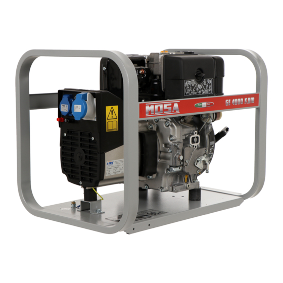
GE 4000 KDM
GE 5000 HBM - BBM
• Gruppo Elettrogeno
• Stromerzeuger
• Generating Set
• Grupo Gerador
• Groupe Electrogene
• Генераторная Установка
• Grupos Electrógenos
• Stroomaggregaten
M A D E
I N
• Skupina generátoru
I T A L Y
3
language
Codice
Code
Code
Codigo
CJ7B00109003
Kodezahl
Código
Код
Code
Kód
Edizione
Edition
Édition
Edición
05.2012
Ausgabe
Edição
Издание
Editie
Edice
Advertisement
Table of Contents

Subscribe to Our Youtube Channel
Related Manuals for Mosa GE 4000 KDM


Summary of Contents for Mosa GE 4000 KDM
- Page 1 USE AND MAINTENANCE MANUAL TRANSLATION OF THE ORIGINAL INSTRUCTIONS – ENGLISH Codice NAKED Code Code Codigo CJ7B00109003 GE 4000 KDM Kodezahl Código GE 5000 HBM - BBM Код Code Kód Edizione Edition Édition • Gruppo Elettrogeno • Stromerzeuger • Skupina generátoru Edición...
-
Page 2: Table Of Contents
M2.5 SAFETY RULES ........................PAG. 8 1. GENERAL INFORMATION OF THE MACHINE DESCRIPTION OF THE MACHINE (GE 4000 KDM) ..............PAG. 10 DESCRIPTION OF THE MACHINE (GE 5000 HBM - BBM) ............PAG. 11 M0.1 RECORDING DATA ........................PAG. 12 2. -
Page 3: Introduction
INTRODUCTION Dear Customer, The Manufacturer shall not be liable for ANY USE OF THE PRO- We wish to thank you for having bought a high quality set. DUCT OTHER THAN THAT PRECISELY SPECIFIED IN THIS Our sections for Technical Service and Spare Parts will work at MANUAL and is thus not liable for any risks which may occur as best to help you if it were necessary. -
Page 4: Ce Mark
CE MARKING GENERATING SETS Any of our product is labelled with CE marking attesting its conformity to appliable directives and also the fulfillment of safety requirements of the product itself; the list of these directives is part of the declaration of conformity included in any machine standard equipment. -
Page 5: Symbols And Safety Precautions
SYMBOLS AND SAFETY PRECAUTIONS GENERATING SETS - LIGHTING TOWERS SYMBOLS IN THIS MANUAL DANGER - The symbols used in this manual are designed to call your GENERAL ADVICE - If the advice is not respec- attention to important aspects of the operation of the machine ted damage can happen to persons or things. -
Page 6: Warnings
WARNINGS GENERATING SETS - LIGHTING TOWERS FIRST AID. In case the operator shold be sprayed by accident, from corrosive liquids a/o hot toxic gas or whate- ver event which may cause serious injuries or death, predispose the first aid in accordance with the ruling labour accident standards or of local instructions. -
Page 7: Safety Rules
SAFETY RULES GENERATING SETS - LIGHTING TOWERS GENERAL SAFETY INSTRUCTIONS • Do not replace the tires with types different from the original + NOTE: the information contained in this manual are ones. subject to change without notice. • Check that the brakes and the optical signaling of the trailer are working properly. - Page 8 SAFETY RULES GENERATING SETS - LIGHTING TOWERS 2.5.1 SAFETY PRECAUTIONS DURING MAINTENANCE ADDITIONAL PRECAUTIONS FOR LIGHTING TOWERS • Make use of qualified personnel to carry out maintenance and troubleshooting. ATTENTION • It is mandatory to stop the engine before performing any maintenance on the machine.
-
Page 9: Description Of The Machine (Ge 4000 Kdm)
DESCRIPTION OF THE MACHINE GE 4000 KDM The generating set is a unit which transforms the mechanical energy, generated by combustion engine, into electric energy, through an alternator. The model GE 4000 is a compact diesel generating set, is easily transported using a trolley. -
Page 10: Description Of The Machine (Ge 5000 Hbm - Bbm)
DESCRIPTION OF THE MACHINE GE 5000 HBM - BBM The generating set is a unit which transforms the mechanical energy, generated by combustion engine, into electric energy, through an alternator. The model GE 5000 is a compact diesel generating set, is easily transported using a trolley. The design incorporates a steel structure with engine and alternator mounted on anti-vibration dampers to increase service life and reduce noise, whilst a steel frame provides protection for the complete machine. -
Page 11: Recording Data
RECORDING DATA The manual is for the range of machines indicated on the front cover. With the scope to facilitate the search of the spare parts and maintain information of the bought machine, is necessary to record some data. Please write the requested data inside the squares to side: Model of machine Serial number of the machine Serial number of the engine... -
Page 12: Machine Unpacking
MACHINE UNPACKING NOTE Be sure that the lifting devices are: correctly mounted, adequate for the weight of the machine with it’s packaging, and conforms to local rules and regulations. When receiving the goods make sure that the product has not suffered damage during the transport, that there has not been rough handling or taking away of parts contained inside the packing or in the set. -
Page 13: Transport And Displacements Covered Units
TRANSPORT AND DISPLACEMENTS COVERED UNITS ATTENTION Transportation must always take place with the engine off, electrical cables and starting battery disconnected and fuel tank empty. Be sure that the lifting devices are: correctly mounted, adequate for the weight of the machine with it’s packaging, and conform to local rules and regulations. - Page 14 INSTALLAZIONE - INSTALLATION - INSTALLATION INSTALACIÓN - LUFTZIRKULATION - INSTALAÇÃO УСТАНОВКА - INSTALLATIE GE 4000 KDM GE 5000 HBM - BBM...
-
Page 15: Installation
INSTALLATION INSTRUCTIONS ENVIRONMENTAL CONDITIONS GENERAL INSTALLATION CRITERIA Installation of a genset has to be planned by qualified and trained technicians, it has to be carried out by a competent ATTENTION organization with qualified personnel and proper equipment. ATTENTION Open gensets (SKID) have to be located in an area protec- ted from rain, snow, high humidity and direct exposure to the sun. - Page 16 In order to avoid potentially dangerous situations, area surrounding genset should be isolated so that unauthorized people will not be able to get close to the unit. Even if MOSA Engine and alternator when in operation produce heat: gensets are manufactured according to electromagnetic •...
- Page 17 INSTALLATION INSTRUCTIONS 2.6.2 Sample of outdoor installation with shelter Floor should be levelled and suitable to sustain genset weight. Thresholds on doors and openings should have a barrier in or- der to avoid liquids leaking. In case it is not possible to provide a door with a barrier, the genset should have a collection base appropriate for the quantity of liquid it contains, in any case dimensions of collection base must be in accordance to the...
- Page 18 INSTALLATION INSTRUCTIONS 2.6.3 For open gensets installed indoors, we recommend: Electro ventilator capacity can be calculated as follows: • The dimensions of the air outlets be such that they have at least the same area of the radiator; Transmitted heat [Kcal/h] •...
-
Page 19: Set-Up For Operation Diesel Engine
SET-UP FOR OPERATION (DIESEL ENGINE) AIR COOLED SYSTEMS BATTERY WITHOUT MAINTENANCE FUEL (WHERE IT IS ASSEMBLED) The supplied battery is generally ready for use. For further details on the type of diesel fuel to use, see the motor Connect the cable + (positive) to the pole + of the battery, by operating manual supplied. -
Page 20: Earthing Kit
EARTHING KIT EARTHING KIT WITHOUT GROUND FAULT INTERRUPTER EARTHING KIT WITH ISOMETER The protection against electric shock from contact indirect is Machines equipped with insulation resistance monitor allow intentionally not to connect the ground terminal PE (12) to an ensured by the “electrical separation” with equipotential bonding earthing system. -
Page 21: M21.2 Starting And Stopping Kholer Diesel Engine
STARTING AND STOPPING (DIESEL ENGINE KOHLER) 21.2 STOPPING Check daily To stop the engine in normal conditions attend the following process: - interrupt the power source, switching off all tools connected. - let the engine run for a few minutes; - Pull the stop lever (28) until the engine stops. -
Page 22: M25 Set-Up For Operation Gasoline Engine
SET-UP FOR OPERATION (ENGINE GASOLINA) AIR COOLED BATTERY WITHOUT MAINTENANCE Check that the dry air filter is correctly installed and that there (WHEN ASSEBLED) are no leaks around the filter which could lead to infiltrations of non-filtered air to the inside of the motor. The supplied battery is generally ready for use. -
Page 23: M26.1 Starting And Stopping Honda Gasoline Engine
STARTING - STOPPING (HONDA GX 200 / 270 / 390 GASOLINE ENGINE) 26.1 check daily ATTENTION: Allow the start-up knob to re-enter slowly, avoiding having it knock against the motor and thereby damaging the start-up system. 5. Once the engine is started, with the starter off, let it turn for NOTE a few minutes before drawing the load. -
Page 24: M26.3 Starting And Stopping B. & S. Gasoline Engine
STARTING - STOPPING (BRIGGS & STRATTON GASOLINE ENGINE) 26.3 STOPPING check daily To stop the engine in an emergency, simply turn the engine switch to the OFF position. Under normal conditions, use the following procedure: 1) stop to draw single-phase current from the auxiliary sockets 2) Wait for a few minutes to allow the machine to cool off, NOTE take however into consideration the prescriptions given in... -
Page 25: M31 Controls (Ge 4000 Kdm)
COMANDI - CONTROLS - COMMANDES - MANDOS - BEDIENELEMENTE - COMANDOS СИСТЕМЫ УПРАВЛЕНИЯ - BEDIENING GE 4000 KDM Pos. Descrizione Description Description Referenzliste Presa di messa a terra Earth terminal Prise de mise à terre Erdanschluss Presa di corrente in c.a. -
Page 26: M31.1 Controls (Ge 5000 Hbm)
COMANDI - CONTROLS - COMMANDES - MANDOS - BEDIENELEMENTE - COMANDOS СИСТЕМЫ УПРАВЛЕНИЯ - BEDIENING 31.1 GE 5000 HBM 23-24 Pos. Descrizione Description Description Referenzliste Presa di messa a terra Earth terminal Prise de mise à terre Erdanschluss Presa di corrente in c.a. A.C. -
Page 27: M31.2 Controls (Ge 5000 Bbm)
COMANDI - CONTROLS - COMMANDES - MANDOS - BEDIENELEMENTE - COMANDOS СИСТЕМЫ УПРАВЛЕНИЯ - BEDIENING 31.2 GE 5000 BBM 23-24 Pos. Descrizione Description Description Referenzliste Presa di messa a terra Earth terminal Prise de mise à terre Erdanschluss Presa di corrente in c.a. A.C. -
Page 28: M37
USING THE GENERATOR OPERATING CONDITIONS WARNING POWER The electrical power expressed in kVA on an electricity- It is absolutely forbidden to connect the unit to the public generating group is the available output power to the reference mains and/or another electrical power source . environmental conditions and nominal values for: voltage, frequency, power factors (cos ϕ). - Page 29 USING THE GENERATOR 37.1 The frequency, and therefore the number of motor revolutions, SINGLE-PHASE LOADS is maintained constant by the motor’s speed regulation system. Power to monophase utilities by means of three-phase Generally, this regulator is of a mechanical type and presents generators requires some operating limitations.
- Page 30 USING THE GENERATOR 37.2 DIFFERENTIAL SWITCH USAGE WITH EAS AUTOMATIC START-UP PANEL The differential switch or differential relay guarantee protection The electricity-generating group in combination with the EAS against indirect contacts due to malfunction currents towards the automatic start-up panel forms a unit for distributing electrical ground.
- Page 31 USING THE GENERATOR 12V C.B. 37.3 GENERATION IN C.C. (Continuous Current) ATTENTION Maximum power in c.c.: The batteries produce explosive gas; sparks, flames, cigaret- P = 120W - V= 12V AC tes, are to be kept far from them. Make sure that when they I = 10A are being recharged there is adequate ventilation around the battery.
-
Page 32: M40.2
TROUBLESHOOTING 40.2 WARNING ● Have qualified personnel do maintenance and troubleshooting work. ● Stop the engine before doing any work inside the machine. If for any reason the machine must be operated while working inside, pay attention mo- ving parts, hot parts (exhaust manifold and muffler, etc.) electrical parts which may be unprotected when the machine is open. ●... - Page 33 TROUBLESHOOTING 40.2.1 GENERATOR Absence of output voltage 1) Protection tripped due to overload 1) Check the load connected and decrease 2) Differential protection device tripped 2) Check the insulation of the whole system: wiring, connections, connected load and check that there are no insulation fault that cause leakage currents to earth 3) Protection devices defective 3) Replace...
-
Page 34: Maintenance
MAINTENANCE WARNING ● Have qualified personnel do maintenance and troubleshooting work. ● Stop the engine before doing any work inside the machine. If for any reason the machine must be operated while working inside, pay at- tention moving parts, hot parts (exhaust manifold and muffler, etc.) electrical parts which may be unprotected when the machine is open. -
Page 35: Storage And Cast Off
STORAGE AND CUST OFF STORAGE CUST OFF + Have qualified personnel disassemble the machine and In case the machine should not be used for more than 30 days, dispose of the parts, including the oil, fuel, etc., in a correct make sure that the room in which it is stored presents a suitable manner when it is to be taken out of service. -
Page 36: Technical Data (Ge 4000 Kdm)
TECHNICAL DATE GE 4000 KDM GENERATOR GE 4000 KDM *Stand-by single-phase power 4 kVA (3.6 kW)/ 230 V / 17.4 A *PRP single-phase power 3.7 kVA (3.3 kW)/ 230 V / 16.1 A Frequency 50 Hz Cos ϕ Output powers according to ISO 8528-1... -
Page 37: Technical Data (Ge 5000 Hbm - Bbm)
TECHNICAL DATE GE 5000 HBM - BBM 1.5.1 GENERATORE GE 5000 HBM GE 5000 BBM *Stand-by single-phase power 4.9 kVA (4.4 kW)/ 230 V / 21.3 A 5 kVA (4.4 kW)/ 230 V / 21.7 A *PRP single-phase power 4 kVA (3.6 kW)/ 230 V / 17.4 A Frequency 50 Hz Cos ϕ... - Page 38 DIMENSIONI - DIMENSIONS - DIMENSIONS - DIMENSIONES ABMESSUNGEN - DIMENSÕES - РАЗМЕРЫ - AFMETINGEN 2.7.1 GE 4000 KDM | GE 5000 HBM - BBM...
-
Page 39: Electrical System Legende
ELECTRICAL SYSTEM LEGENDE : Alternator E3 : Open circuit voltage switch I6 : Start Local/Remote selector N9 : UP/DOWN button mast : Wire connection unit F3 : Stop push-button L6 : Choke button O9 : Hydraulic unit solenoid valve C : Capacitor G3 : Ignition coil M6 : Switch CC/CV P9 : Hydraulic unit engine... -
Page 40: M61
SCHEMA ELETTRICO - ELECTRIC DIAGRAM - SCHEMAS ELECTRIQUES - ESQUEMA ELÉCTRICO - STROM- LAUFPLAN - ESQUEMA ELÉCTRICO - ЛЕГЕНДА ЭЛЕКТРИЧЕСКАЯ СХЕМА - ELECTRISCH GEDEELTE GE 3500 KBM | GE 5000 BBM | GE 7000 BBM | GE 8000 BBT... - Page 41 SCHEMA ELETTRICO - ELECTRIC DIAGRAM - SCHEMAS ELECTRIQUES - ESQUEMA ELÉCTRICO - STROM- LAUFPLAN - ESQUEMA ELÉCTRICO - ЛЕГЕНДА ЭЛЕКТРИЧЕСКАЯ СХЕМА - ELECTRISCH GEDEELTE 61.1 GE 3500 HBM | GE 5000 HBM | GE 7000 HBM | GE 8000 HBT...
- Page 42 SCHEMA ELETTRICO - ELECTRIC DIAGRAM - SCHEMAS ELECTRIQUES - ESQUEMA ELÉCTRICO - STROM- LAUFPLAN - ESQUEMA ELÉCTRICO - ЛЕГЕНДА ЭЛЕКТРИЧЕСКАЯ СХЕМА - ELECTRISCH GEDEELTE 61.2 GE 3500 HBM - KBM | GE 4000 KDM | GE 5000 HBM - BBM...
Need help?
Do you have a question about the GE 4000 KDM and is the answer not in the manual?
Questions and answers