Table of Contents
Advertisement
Quick Links
USE AND MAINTENANCE MANUAL
TRANSLATION OF THE ORIGINAL INSTRUCTIONS – ENGLISH
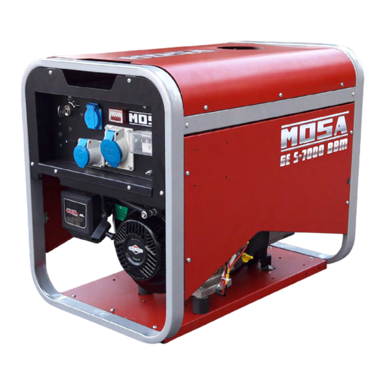
S-RANGE
GE S-7000 HBM - BBM (STAGE V)
GE S-8000 HBM - BBM (STAGE V)
• Gruppo Elettrogeno
• Stromerzeuger
• Generating Set
• Grupo Gerador
• Groupe Electrogene
• Генераторная Установка
• Grupos Electrógenos
• Stroomaggregaten
M A D E
I N
• Skupina generátoru
I T A L Y
3
language
Codice
Code
Code
Codigo
CK7P00109003
Kodezahl
Código
Код
Code
Kód
Edizione
Edition
Édition
Edición
07.2019
Ausgabe
Edição
Издание
Editie
Edice
Advertisement
Table of Contents


Need help?
Do you have a question about the GE S-7000 HBM and is the answer not in the manual?
Questions and answers