Table of Contents
Advertisement
Quick Links
Advertisement
Table of Contents

Related Manuals for Sonel CMP-1010


Summary of Contents for Sonel CMP-1010
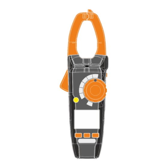
- Page 1 USER MANUAL DIGITAL CLAMP METER CMP-1010 Version 1.01 11.09.2023...
- Page 2 CMP-1010 True RMS multimeter is intended for measuring direct and alternating voltage, direct and alternating current, resistance, capacitance, frequency, duty cycle (filling) and temperature and for testing diodes and circuit continuity. The most important features of CMP-1010 include: possibility of carrying out measurements in the output cir- cuits of inverters and frequency converters, ...
-
Page 3: Table Of Contents
6.1.2 Display backlight ............57 RANGE button ..............58 Button MODE/INRUSH ............. 58 6.3.1 Changing the measurement mode ......58 6.3.2 INRUSH function ............58 PEAK/VFD button ............. 59 6.4.1 PEAK MAX/PEAK MIN function ......... 59 CMP-1010 – USER MANUAL... - Page 4 7 Replacing the batteries ..........61 8 Maintenance and care ..........62 9 Storage ............... 63 10 Dismantling and disposal ......... 63 11 Specifications ............64 11.1 Technical data ..............64 11.2 Operating data ..............67 12 Service ................ 68 CMP-1010 – USER MANUAL...
-
Page 5: Introduction
Indication of possible problems is preceded by symbol WARNING CMP-1010 meter is designed to measure the AC/DC cur- rent and voltage, frequency, resistance, capacitance, as well as to test the circuit continuity and diodes. Any ap-... -
Page 6: Safety
a device with damaged insulation of test leads, a meter stored for an excessive period of time in disadvan- tageous conditions (e.g. excessive humidity). repairs may be carried out only by an authorised service point. CMP-1010 – USER MANUAL... -
Page 7: Safety Symbols
Protection class II – double insulation Terminals with this marking cannot be connected to a circuit where the voltage to ground exceeds the maximum safe voltage of the device. CMP-1010 – USER MANUAL... -
Page 8: Preparing The Meter For Operation
discharge capacitors in the tested power sources, disconnect the power supply when measuring the resistance and diode tests, turn off the meter and disconnect test leads before removing the back cover to replace the batteries. CMP-1010 – USER MANUAL... - Page 9 This is a normal phenomenon, which results from the input sensitivi- ty with high input resistance. When connected to a circuit, the read-out will stabilize and the meter will provide the cor- rect value. CMP-1010 – USER MANUAL...
-
Page 10: Functional Description
4 Functional description 4.1 Measuring terminals and functions CMP-1010 – USER MANUAL... - Page 11 Hz% – measurement of alternating voltage, measurement of frequency and duty cycle OFF – the meter is switched off LoZ Hz% – low impedance measurement of alternating voltage, measurement of frequency and duty cycle CMP-1010 – USER MANUAL...
- Page 12 Measurement of current and voltage behind the inverter, fre- quency converter, in the VFD system (press and hold) COM measuring terminal Measuring input, common for all measuring functions excluding current. Measurement terminal VΩHz% CAPTemp Measuring input for measurements other than current measurement. CMP-1010 – USER MANUAL...
-
Page 13: Display
Measurement of capacitance Ω Measurement of resistance Measurement of frequency Duty cycle measurement °C / °F Temperature measurement in Celsius / Fahrenheit degrees Low-impedance measurement Constant signal Alternating signal Low battery – Negative read-out value Exceeded measurement range CMP-1010 – USER MANUAL... -
Page 14: Leads
WARNING Connecting wrong leads may cause electric shock or measurement errors. The probes are equipped with additional removable tip guards. The probes must be stored in a designated area. CMP-1010 – USER MANUAL... -
Page 15: Measurements
read the measurement result on the display. If DC current is measured and the meter is not attached to the tested circuit, but it still indicates a non-zero value, then you must reset it by pressing and holding button. CMP-1010 – USER MANUAL... -
Page 16: Non-Contact Voltage Detector
The type and thickness of the insulation, distance from the power source, shielded cables and other factors may affect the operation of the tester. If you are unsure about the test result, check the presence of voltage in a differ- ent way. CMP-1010 – USER MANUAL... -
Page 17: Voltage Measurement
connect black test lead to COM terminal, and red test lead to VΩHz% CAPTemp terminal, contact the tips of test probes to the points of measurement, read the measurement result on the display. CMP-1010 – USER MANUAL... -
Page 18: Frequency Measurement
connect black test lead to COM terminal, and red test lead to VΩHz% CAPTemp terminal, contact the tips of test probes to the points of measurement, read the measurement result on the display. CMP-1010 – USER MANUAL... -
Page 19: Loz Measurement (Elimination Of Interference And Induced Voltages)
contact the tips of test probes to the points of measurement; the best solution is to disconnect one side of the tested element, to prevent the remaining part of the circuit interfere with the read-out of the resistance value, read the measurement result on the display. CMP-1010 – USER MANUAL... -
Page 20: Circuit Continuity Test
read the test result on the display – the forward voltage is dis- played. For a typical silicon rectifier diode, it is approx. 0.7 V, and for a germanium diode it is approx. 0.3 V CMP-1010 – USER MANUAL... -
Page 21: Measurement Of Capacitance
press MODE/INRUSH button to display nF on the screen, connect black test lead to COM terminal, and red test lead to VΩHz% CAPTemp terminal, contact the probe tips to the tested capacitor, read the measurement result on the display. CMP-1010 – USER MANUAL... -
Page 22: Temperature Measurement
read the measurement result on the display, after completing the measurements, disconnect the probe from the meter. CAUTION! Risk of burns. The temperature probe heats up, adapting to the temperature of tested object. CMP-1010 – USER MANUAL... -
Page 23: Special Features
This function is not available for diode test, continuity test and duty cycle. 6.1.2 Display backlight Pressing and holding REL button for 2 seconds will turn ON/OFF the display backlight function. CMP-1010 – USER MANUAL... -
Page 24: Range Button
This function is available only when measuring AC current. While INRUSH is active, autoranging is disabled, therfore it is advised to start the function after connecting test leads to the measurement point. Running INRUSH before that may cause overrange symbols to appear. CMP-1010 – USER MANUAL... -
Page 25: Peak/Vfd Button
set the rotary switch to the voltage or current measurement posi- tion, press and hold the PEAK/VFD button until the "VFD" symbol ap- pears. To disable the mode, press and hold the PEAK/VFD button. CMP-1010 – USER MANUAL... -
Page 26: Button Hold
wait until the meter reaches the measurement readiness, release MODE/INRUSH button. When the automatic shutdown is deactivated, the display does not show Each pass of the rotary switch through "OFF" position with non-pressed MODE/INRUSH button, will activate again the Auto-Off function. CMP-1010 – USER MANUAL... -
Page 27: Replacing The Batteries
To avoid electric shock, do not use the meter if the bat- tery compartment cover is not in place or is not properly fastened. CMP-1010 is powered by by three LR03 AAA 1.5 V batteries. It is recommended to use alkaline batteries. To replace the batteries: ... -
Page 28: Maintenance And Care
6. IF THE METER IS TO BE STORED FOR LONGER THAN 60 DAYS, remove the batteries and keep them separately. The electronic system of the meter does not require maintenance. CMP-1010 – USER MANUAL... -
Page 29: Storage
Before the equipment is sent to a collection point, do not dis- mantle any elements. Observe local regulations concerning disposal of packages, waste batteries and accumulators. CMP-1010 – USER MANUAL... -
Page 30: Specifications
400.0 V 0.1 V 1000 V All AC voltage ranges are specified from 10% to 100% of range Input impedance: 9 MΩ Frequency range: 50 Hz…1000 Hz Overload protection: 1000 V DC/AC RMS CMP-1010 – USER MANUAL... - Page 31 (1.5% m.v. + 2 digits) 60.00 kΩ 0.01 kΩ 600.0 kΩ 0.1 kΩ (2.5% m.v. + 3 digits) 6.000 MΩ 0.001 MΩ (3.5% m.v. + 5 digits) 60.00 MΩ 0.01 MΩ Overload protection: 300 V DC/AC RMS CMP-1010 – USER MANUAL...
- Page 32 0.1 or 1C ± (3% m.v. + 5C) -4.0…+1832F 0.1 or 1F ± (3% m.v. + 9F) The accuracy of the temperature probe is not taken into account Overload protection: 300 V DC/AC RMS CMP-1010 – USER MANUAL...
-
Page 33: Operating Data
................EN 61326-1, EN 61326-2, EN 301 489-1, EN 301 489-17 ..................IEC 61010-1, EN 61010-02-032, EN 61010-02-033 ............RoHS 2011/65/EU, (EU) 2015/863, EN 62479:2010, EN 50663:2017 quality standard ..........................ISO 9001 CMP-1010 – USER MANUAL... -
Page 34: Service
The provider of guarantee and post-guarantee services is: SONEL S.A. Wokulskiego 11 58-100 Świdnica Poland tel. +48 74 884 10 53 (Customer Service) e-mail: customerservice@sonel.com web page: www.sonel.com CAUTION! Service repairs must be performed only by the manufacturer. CMP-1010 – USER MANUAL...
Need help?
Do you have a question about the CMP-1010 and is the answer not in the manual?
Questions and answers