Table of Contents
Advertisement
Quick Links
Advertisement
Table of Contents

Related Manuals for Sonel CMP-400


Summary of Contents for Sonel CMP-400
- Page 1 OPERATING MANUAL AC CLAMP METER CMP-400 Version 1.6...
- Page 2 The CMP-400 digital clamp meter has been designed for the purpose of clamp measurements of alternative current. Furthermore, the meter may be used to measure direct and al- ternative voltages, resistance, frequency, temperature and to test diodes. Main features of the CMP-400 device are the following: •...
-
Page 3: Table Of Contents
INTRODUCTION ........... 5 SAFETY ..............6 ........... 8 NTERNATIONAL AFETY YMBOLS PREPARATION OF THE METER FOR OPERATION ..............8 FUNCTIONAL DESCRIPTION......9 EASUREMENT SOCKETS AND ELEMENTS OF SELECTION OF THE ..............9 MEASUREMENT FUNCTION 4.1.1 Sockets ................10 4.1.2 Elements of selection of the measurement function ... 10 ................ - Page 4 DISMANTLING AND UTILIZATION ....22 ATTACHMENTS ..........22 12.1 T ..............22 ECHNICAL DATA 12.2 S ............25 TANDARD EQUIPMENT 12.3 M ..............26 ANUFACTURER...
-
Page 5: Introduction
WARNING: The purpose of the CMP-400 meter is to realise measure- ments of the current, directs and alternative voltages, re- sistance, frequency, temperature and diode testing. Using... -
Page 6: Safety
WARNING: The CMP-400 meter may be operated solely by qualified and properly authorised personnel for work at electric installa- tions. Using the meter by unauthorised personnel may lead to its damage and constitutes a source of a serious risk for the user. - Page 7 ⇒ If it is damaged and completely or partially out of order ⇒ If the insulation of the test leads has been damaged ⇒ If it has been stored for an excessive period of time in inad- equate conditions (e.g. if it is humid) •...
-
Page 8: International Safety Symbols
International Safety Symbols This symbol, adjacent to another symbol or terminal, indi- cates the user must refer to the manual for further infor- mation. This symbol, adjacent to a terminal, indicates that, under normal use, hazardous voltages may be present Double insulation 3 Preparation of the meter for operation Having purchased the meter examine completeness of the con-... -
Page 9: Functional Description
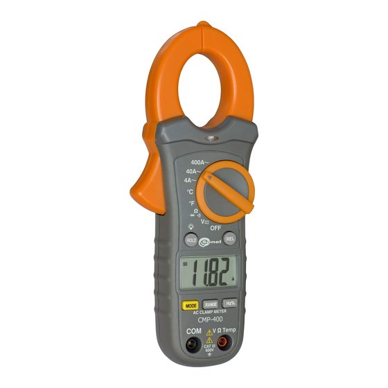
4 Functional description Measurement sockets and elements of selection of the measurement function Ω Illustration 1. CMP-400... -
Page 10: Sockets
4.1.1 Sockets measurement socket V/Ω/TEMP Measurement socket for the purpose of measurements of di- rect and alternative voltages resistance, frequency and tem- perature. measurement socket COM Measurement socket common for all the measurement func- tions except of current measurements (connection to the mass of the device). - Page 11 Hz/% button • Frequency/duty cycle selection battery cover LCD display Illustration 2. LCD display of the CMP-400 meter – minus sign AC, DC – AC (alternating current) and DC (direct currrent) AUTO – AutoRange mode – diode test mode – continuity check mode HOLD –...
-
Page 12: Test Leads
+ _ _ – low battery indication BAT – low battery indication (change battery) Test leads The manufacturer guarantees correct measurement indications provided original test leads are used. WARNING: Connection of inadequate test leads constitutes a risk of electric shock with a dangerous voltage or may be a cause of measurement errors. -
Page 13: Ac And Dc Voltage Measurements
WARNING: Do not commence measurements if the test leads are con- nected to the meter. In order to realise a measurement of alternative current, it is necessary to realise the following actions: • Set the Function switch to the 400A~ or 40A~ or 4A~ range, if the range of the measured is not known, select the highest range first, •... -
Page 14: Resistance Measurements
• having done the measurement disconnect the test leads from the meter. Resistance measurements WARNING: Measurements must not be realised in live circuits. Capaci- tors must be discharged. WARNING: Do not realise measurements if the battery compartment is open. In order to realise a measurement of the resistance it is neces- sary to realise the following actions: •... -
Page 15: Continuity Measurements
Continuity Measurements WARNING: Measurements must not be realised in live circuits. Capaci- tors must be discharged. WARNING: Do not realise measurements if the battery compartment is open. In order to realise continuity test it is necessary to realise the following actions: •... -
Page 16: Frequency Or % Duty Cycle Measurements
WARNING: Do not realise measurements if the battery compartment is open. In order to realise continuity test it is necessary to realise the following actions: • place the rotational selector in the position Ω • connect the red test lead to sockets V/Ω/TEMP and the black one to sockets COM, •... -
Page 17: Temperature Measurements
Temperature measurements WARNING: Do not realise measurements if the battery compartment is open. WARNING: To avoid electric shock, disconnect both test probes from any source of voltage before making a temperature meas- urement. WARNING: To avoid electric shock, be sure the thermocouple has been removed before changing to another measurement function. -
Page 18: Non-Contact Ac Voltage Measurements
Non-Contact AC Voltage Measurements WARNING: Risk of Electrocution. Before use, always test the voltage de- tector on a known live circuit to verify proper operation. In order to realise the test it is necessary to realise the following actions: • touch the current clamp to the live conductor or insert into the live side of the electrical outlet, •... -
Page 19: Relative Mode
• press the RANGE button - the “Auto Range” display indicator will turn off, • press the RANGE button to step through the available ranges until you select the range you want, • press and hold the RANGE button for 2 seconds to exit the ManualRanging mode and return to AutoRanging. -
Page 20: Before You Send The Meter To Be Serviced
7 Before you send the meter to be ser- viced Before sending the instrument to be repaired call the workshop, since it is possible the meter is not damaged, and the problem has occurred for some other reason. Elimination of damage to the meter must be realised solely in workshops authorised by the manufacturer. -
Page 21: Replacement Of The Batteries
8 Replacement of the batteries The CMP-400 meter is supplied by means of one 9V battery. It is recommended to use alkaline battery. Attention: When making measurements with a battery's mnemonic on, one must take into account additional indefinite measure- ment uncertainty or unstable working of the meter. -
Page 22: Storage
10 Storage In the case of storage of the device, the following recommenda- tions must be observed: • Disconnect all the test leads from the meter, • Make sure the meter and its accessories are dry, • In the case the meter is to be stored for a prolonged period of time, the battery must be removed from the device. - Page 23 DC voltage measurement Range Resolution Basic uncertainty ± (0,8% m.v. + 2 digits) 400,0mV 0,1mV 4,000V 0,001V ± (1,5% m.v. + 2 digits) 40,00V 0,01V 400,0V 0,1V ± (2% m.v. + 2 digits) 600V AC voltage measurement Range Resolution Basic uncertainty ±...
- Page 24 Duty Cycle Range & Res- Basic Accuracy olution 10.0…94.9% unspecificated Pulse width: 100µs…100ms, Frequency: 30Hz…15kHz; Sensitivity: 30…5kHz:10Vrms min. 5kHz…15kHz:40Vrms min. Temperature measurement Range Basic uncertainty * -20.0…760,0°C ± (3% m.v. + 5°C) -4.0…1400,0°F ± (3% m.v. + 9°F) * probe (K type) accuracy not included Other technical data a) Measurement category in acc.
- Page 25 ................EN 61010-2-032 u) Quality standard ............ISO 9001 12.2 Standard equipment The standard set provided by the manufacturer includes the fol- lowing components: • The CMP-400 meter, • Test leads (2 pieces), • 9V battery, • K-Type temperature probe, •...
- Page 26 SONEL S. A. ul. Wokulskiego 11 58-100 Świdnica Tel: +48 74 858 38 60 Fax: +48 74 858 38 09 E-mail: export@sonel.pl Web page: www.sonel.pl Note: Service repairs must be realised solely by the manufactur- Made in China for SONEL S.A.
Need help?
Do you have a question about the CMP-400 and is the answer not in the manual?
Questions and answers