Table of Contents
Advertisement
Quick Links
DMC2
Dynalite Modular Controller (2 Output Modules)
Installation Instructions
Warning..................................................... 2
Features..................................................... 2
Important Safeguards................................... 2
Internal View............................................... 3
Mounting.................................................... 4
Module mounting......................................... 5
Dynalite manufactured by WMGD Pty Ltd (ABN 33 097 246 921) Unit 6, 691 Gardeners Road Mascot NSW 2020 Australia Tel: +61 2 8338 9899 Fax: +61 2 8338 9333
E-Mail: support.controls@philips.com
DMC2 Installation Instructions Rev B Specifications subject to change without notice
Final Checks.............................................. 6
Dimensions................................................. 7
Specifications.............................................. 8
Web: http://philips.com/dynalite
JOSEPH JOUKHADAR
sels@automated.net.au
+61 2 9247 0731
Suite 4, Level 5
37 Pitt Street
Sydney NSW 2000
Advertisement
Table of Contents

Related Manuals for Philips Dynalite DMC2


Summary of Contents for Philips Dynalite DMC2
-
Page 1: Table Of Contents
DMC2 Installation Instructions Rev B Specifications subject to change without notice Dynalite manufactured by WMGD Pty Ltd (ABN 33 097 246 921) Unit 6, 691 Gardeners Road Mascot NSW 2020 Australia Tel: +61 2 8338 9899 Fax: +61 2 8338 9333 E-Mail: support.controls@philips.com Web: http://philips.com/dynalite... -
Page 2: Warning
Special Programming – Once assembled, powered and terminated correctly, this device will operate in basic The DMC2 is only compatible with Philips mode. A new Philips Dynalite user interface on the same Dynalite modules. network will turn all output lighting channels on from button 1 and off from button 4 allowing testing of network •... -
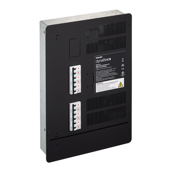
Page 3: Internal View
Control Communication bus connection module 2 install location High voltage barrier Comms module Communication bus connection install location Data cable entry points For spare parts, please call your nearest Philips Dynalite Customer Service Centre. DMC2 Installation Instructions Rev 03... -
Page 4: Mounting
Mounting For surface mounting, four mounting points have been provided. Refer to the location of the mounting points in the dimension drawings on page 7 of this document. For recess mounting, four holes suitable for M6 (1/4”) fasteners have been provided on side walls as shown below. Minimum spacing between studs is 380mm (15”), minimum mounting depth 103mm (4.1”) Ensure no dust or other debris enters the device during... -
Page 5: Module Mounting
Module mounting Before starting: Remove the knockouts you intend to run the supply cables through – lighting group supply and network supply first – then mount the DMC2 (surface or recessed, as required). Once the unit is secured to the intended mounting wall follow the steps below for the different module mounting. Supply Cables: The supply input terminals are located on the DSM Module toward the top of the enclosure and consist of Neutral and Phase terminals, all of which will accept up to 16mm... -
Page 6: Final Checks
1. After removing both front covers and the required knockouts for the power supply, networking cable and lighting group channels, mount the unit in its desired location. Once secured, the DMC2 unit is ready for the internal modules to be mounted. -
Page 7: Dimensions
Dimensions 285mm 11.2in 380mm 15.0in 103mm 4.1in DMC2 Installation Instructions Rev 03... -
Page 8: Specifications
DMC2 Installation Instructions Rev 03 Specifications subject to change without notice Dynalite manufactured by WMGD Pty Ltd (ABN 33 097 246 921) Unit 6, 691 Gardeners Road Mascot NSW 2020 Australia Tel: +61 2 8338 9899 Fax: +61 2 8338 9333 E-Mail: support.controls@philips.com Web: http://philips.com/dynalite...
Need help?
Do you have a question about the Dynalite DMC2 and is the answer not in the manual?
Questions and answers