Advertisement
Quick Links
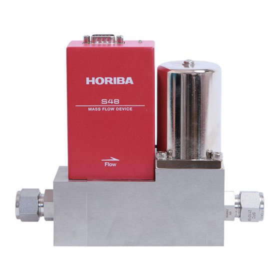
INSTRUCTION MANUAL
MASS FLOW CONTROLLER / METER
S48(M)-CR series
CODE: CI300006C
1.SPECIFICATIONS
*1: SCCM、SLM is a symbol of gas flow rate(ml/min、l/min:0℃、1013hpa(1atm))
*2: Accuracy,linearity, repetition reproducibility and response are the guarantees to proofreading gas ( N2) and a specified
flow rate range.
*3: Response time is the time it takes for a flow output signal to arrive and stabilize within the setpoint ±2% F.S. range
during a rising response.
*4: (D) means differential pressure、(G) means gauge pressure.
*5: The operation differential pressure may differ depending on the specifications.
2.NAME
Dsub9pin connector
LED ramp
(Power supply,Flow input signal,Flow output signal)
(A lamp comes on in green (substrate normalcy)
at the time of power activation.)
*Only 24VDC power supply
Zero point adjustment trimmer
Inlet Fitting
Please ask separately about a special joint
3. ELECTRICAL CONNECTION
Use connector: D-subminiature9 compact pin-connector (#4-40 UNC inch screw thread type)
* Please keep in mind that screw threads differ by M3 engagement screw type.
3-1-1) ±15VSPEC
Pin No.
1
Valve override open/close signal *1 *2
2
Analog flow rate output signal: 0 to 5VDC *3
3
Power supply input (+15VDC, 140mA)
4
Power common
5
Power supply input (-15VDC, 140mA)
6
Analog flow rate setting signal: 0 to 5VDC *4
7
Signal common
8
Signal common
9
N.C.
*1.For Mass Flow Meter is N.C.
*2.+15VDC input : OPEN, -15VDC input : CLOSE.
It becomes control mode when not inputted ±15V.
*3. Input impedance is more than 1MΩ.
Inside the S48, the power supply COM is connected to the signal COM.
The various signals of the S48 are controlled using the signal COM as the reference.
In order to prevent the common voltage variation by valve driving current,the power supply of Pin No.4 and Signal
common of Pin No.7 need to be connected toward GND side of an electric supply source
If the connection is incorrect, there is possibility that MFC does not work properly.
It is connected inside MFC signal common of Pin No.7 and Pin No.8
N.C.: Non connection.
3-1-2) Connection with an electric system
Please wire electric system connection according to the connector connection table.
±15VDC power spec: Direct-current electricity
±
+15V
5% 150mA
- 15V±5% 150mA
3-2-1) +24VSPEC
Pin No.
1
Valve override open/close signal *1, *2
2
Flow rate output signal : 0 to 5VDC *3
3
Power supply input +24VDC (+20V~28V)
4
Power common
5
N.C.
6
Flow rate setting signal : 0.1 to 5VDC *4
7
Signal common
8
Signal common
9
N.C.
*1.For Mass Flow Meter is N.C.
*2.15~24V input valve forcible opening.
0~-15V input valve forcible closing.
*3. Maximum load Resistance less than 250Ω (4~20mA) .
*4. Input impedance is 1MΩ(0~5V/1~5V/0~10V).
Inside the S48, the power supply COM is not connected to the signal COM.
The various signals of the S48 are controlled using the signal COM as the reference.
In order to prevent the common voltage variation by valve driving current,the power supply of Pin No.4 and Signal
common of Pin No.7 need to be connected toward GND side of an electric supply source
If the connection is incorrect, there is possibility that MFC does not work properly.
It is connected inside MFC signal common of Pin No.7 and Pin No.8.
N.C.: Non connection.
3-2-2)Connection with an electric system
Please wire electric system connection according to the connector connection table.
+24VDC power spec: Direct-current electricity
+24V±5% 200mA
4. CAUTION AND REMINDERS
1) Be sure that all piping is properly tightened with no leaks and completely purged.
Insufficient purging may cause troubles such as particulate contamination, clogging, throughput decreasing, etc.
2) Warm-up
Outlet Fitting
After plugging in the power, keep it without airflow for more than 5 minutes(recommendation 30 minutes).
Even when it has no warm-up, trouble is not in operation, but flow accuracy worsens.
3) Zero point adjustment
When you use a zero compensation function, please do not put pressure on the inside of a main part.
The right zero point compensation is not performed.
Signal Name
Signal Name
Moreover, in consideration of the stability of a sensor, after at least 1 minute or more passes after a gas stop, I
recommend using a zero compensation function.
The function to adjust a zero point automatically is attached to this product.
When 0VDC is inputted into a flow rate set signal for more than about 4 minutes, a zero point is automatically
adjusted to zero.
4) Please use a gas filter, in order to remove the particle and impurities which flow into this equipment from the upper
stream of piping.
5) Storage temperature is 0~80℃. Please avoid preservation in the temperature span exceeding this temperature.
Moreover, please do not let me dew. There is possibility of breakage.
6) Since there is fear of an electric shock, please do not open a case.
7) An analog flow signal may be transitionally outputted in the range of power supply voltage.
When you use an analog flow signal, be careful of the input electric strength of equipment.
8) If ON/OFF is repeated for a power supply for a short time, it may have bad influences, such as malfunction.
Please use 3 seconds or more during the OFF of a power supply. Moreover, since extraction and insertion of the state
where only some of power supplies and signals were impressed, or connector may cause failure, please avoid it.
9) Please do not put power or excessive pressure with a main part and a cable impossible for.
10) At our company, a flow value is converted into 25℃, 1013 hPa (1atm) or 0℃, and 1013 hPa (1atm), and is
proofread. "CCM", "LM", "SCCM", and "SLM" are the signs by which the flow (ml/min, l/min) of the gas in the
following state is denoted, respectively.
CCM,LM : 25℃,1013hPa(1atm)
SCCM,SLM : 0℃,1013hPa(1atm)
11) contact us if using the product with gases other than those labeled on the backside of the product and the
calibration gas (N2).
12) handling the product should be careful. Holding the case part of the product may cause falling and damage to the
product, therefore be sure to hold the block part of the product when carrying.
13) The control valve installed in the product is not designed to provide complete shut-off. It is recommended to
install separate shut-off valves if required.
14) Please keep in mind that the gas more than F.S. flows when a control valve is made full open or failure occurs by a
certain cause.
This instruction manual is subject to alteration without a notice.
5. PRODUCT WARRANTY
1)Period
The product is warranted for one (2) year (parts and labor) from date of shipment
Repair will be provided free of charge during this period if the products is returned to HORIBA STEC or authorized
service representative with a description of the problem.
HORIBA STEC is not responsible for damage due to customer neglect or improper operation of this product.
2)Scope
Warranty coverage is restricted to this product only.HORIBA STEC is not responsible for damage to other
components due to improper operation of this product
3) Warranty
Replacement parts are warranted for ninety (90) days or the remainder of the warranty period(whichever is longer).
4)HORIBA STEC is not responsible for damage due to:
a)Natural disasters
b)Miss-operation or abuse of this product
c)Operation or storage in an unsuitable environment Operation outside of the rated specifications
e)Unauthorized alterations or retrofits to this product.
Repair expense with / without charge is to be determined as examination and / or disassembly of the returned
Examples for out of scope of responsibility by HORIBA STEC:
*In case of use of high reaction gas ,dogging due to incomplete purge or leakage,etc,in gas line.
*Contamination or clogging by dust or mist,etc.
Repair expense with/without charge is to be determined as examination and/or disassembly of the returned products
5)For questions of service please contact.
Japan:
HORIBA STEC,CO.,LTD
11-5,Hokodate-cho,Kamitoba,Minami-ku,Kyoto,601-8116 Japan
http://www.horiba-stec.jp/
Manufacturer:
HORIBA Precision Instruments (Beijing) Co.,Ltd.
Building 1, No.3 Xixing Road, Houshayu Town, Shunyi District, Beijing 101318 China
TEL: +86 10 84929402/9404/9453
FAX: +86 10 84927216
E-MAIL: sales@horibaprecision.com
http://www.horibaprecision.com
Advertisement

Related Manuals for horiba S48 CR Series


Summary of Contents for horiba S48 CR Series
- Page 1 The product is warranted for one (2) year (parts and labor) from date of shipment - 15V±5% 150mA Repair will be provided free of charge during this period if the products is returned to HORIBA STEC or authorized *1: SCCM、SLM is a symbol of gas flow rate(ml/min、l/min:0℃、1013hpa(1atm))...
- Page 2 If the state where the input was carried out for 0VDC to the flow rate set signal continues for more than about 4 minutes, This document is attached in compliance with revisions in the CE Marking Directive or UKCA Marking Regulations. All HORIBA Precision Instruments a zero point will be adjusted automatically.
Need help?
Do you have a question about the S48 CR Series and is the answer not in the manual?
Questions and answers