
Related Manuals for horiba DS-51


Summary of Contents for horiba DS-51
- Page 1 For more information, please contact us: ExpotechUSA 10700 Rockley Road Houston, Texas 77099 281-496-0900 [voice] 281-496-0400 [fax] E-mail: sales@expotechusa.com Website: www.ExpotechUSA.com...
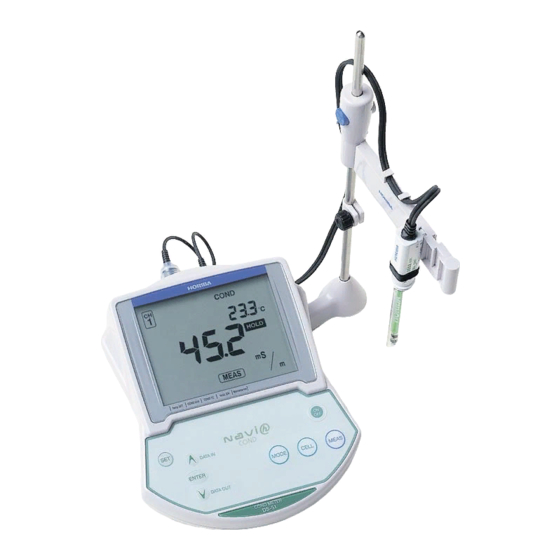
- Page 3 ■ Preface Thank you for purchasing the DS-51 conductivity meter. This meter has a large-sized LCD display, which enables to use the varied functions by simple operations, and especially will be convenient to use in laboratory. Carefully read this manual before using the meter.
- Page 4 Precautions for use ■ CE Marking This product is in conformity with the following directives and standards: Directives:The EMC Directives 89/336/EEC The Electrical Product Safety Directive 73/23/EEC Standards: EN61326: 1997+A1:1998 (EMISSION: Class B, IMMUNITY Category: Minimum Requirement) EN61010-1: 2001 Installation Environment This product is designed for the following environment.
-
Page 5: Safety Precautions
Precautions for use ■ Type and Definition of Signal Words For the safety use, the meter is equipped with the Warning Labels to alert every operator and user to the possible risk and danger. Before using understanding each message. The meaning of signal words are as follows: This indicates an potentially hazardous situation which, (WARNING) if not avoided, will result in death or serious injury. - Page 6 Precautions for use ● Indication WARNING This indicates an potentially hazardous situation which, if not avoided, will result in death or serious injury. CAUTION This indicates a potentially hazardous situation which, if not avoided, may result in minor or moderate injury. It may also be used to alert unsafe practices.
- Page 7 Precautions for use ■ Cautionary Items ● Precautions Do not give physical shock to the meter like dropping or hitting. ● Avoid water or solution from being contact with the meter body. ● Water or solution, if contacts with the meter, may cause the meter breakage.
-
Page 8: Table Of Contents
Maintenance mode ................ 31 Chapter 4 RS-232C communications ..Cautions before use ............39 Command list ..............40 On-line operation commands ........42 Data request commands and responses..... 46 Communication example using the Hyper Terminal .. 54 DS-51... - Page 9 Operation flowcharts............. 81 Pin layout of special cables.......... 82 7.5.1 RS-232C communications cable ........... 82 7.5.2 Cable for CITIZEN printer .............. 82 7.5.3 Cable for SEIKO printer ..............82 Spare and optional parts ..........83 7.6.1 Optional parts ................84 HORIBA...
-
Page 10: Chapter 1 Overview Of Cond Meter
Overview of COND Meter This chapter explains the part names, how to connect the electrodes, how to replace the batteries, and precautions when using the meter. Package contents The following items are shipped with each HORIBA COND meter. Name Q’ty Meter... -
Page 11: Functions
Chapter 1 Overview of COND Meter 1.2 Functions Functions The COND meter features the following functions. ● Measurement items Items Required electrode/standard solution Conductivity Conductivity electrode Conductivity standard solution Salinity Resistivity Temperature − ● Functions An overview of the functions found on the COND meter is shown below. Page Function Explanation... - Page 12 OFF if no keys are touched 30 minutes. Remaining data Displays the remaining memory. page memory Data memory Deletes data in memory. page clear Initializing Initializes all settings to the default values. page settings Printing test Conducts a printing test. page DS-51...
-
Page 13: Explanation Of Part Names
Chapter 1 Overview of COND Meter 1.3 Explanation of part names Explanation of part names The COND meter has the following parts: 1.3.1 Meter body Serial communication connector CH1 measurement electrode Grounding AC connector CH1 temperature electrode 1.3.2 Display 入力 CH Input channel Error No., エラーNo. - Page 14 Displayed during manual temperature compensation. Not displayed during automatic temperature compensation. HOLD Displayed while the data is held (HOLD status). Blinks during measurement or calibration. Meter mode Displayed when in Measurement mode. Displayed when in Calibration mode. DS-51...
-
Page 15: Operation Keys
Chapter 1 Overview of COND Meter 1.4 Operation keys Operation keys This section describes the functions of the keys. Name Description MEAS key Returns to the Measurement mode. Starts measurement. MODE key Selects measurement item. SET key Selects setting item. CELL key Enters the Cell Constant Setting mode. -
Page 16: Assembling The Electrode Stand
Chapter 1 Overview of COND Meter 1.5 Assembling the electrode stand Assembling the electrode stand Mount the electrode stand on the rear of the meter as shown in the figure below. DS-51... -
Page 17: Connecting The Electrodes
Chapter 1 Overview of COND Meter 1.6 Connecting the electrodes Connecting the electrodes Connect the electrodes to the COND meter using the following procedure: ・ Do not allow any water to come into contact with the connector. ・ Do not touch the connector with uncleaned hands. ・... - Page 18 1.6 Connecting the electrodes ● Temperature connector Insert the temperature connector into the jack on the main unit of the COND meter. When the temperature electrode is not connected (or is connected improperly), the automatic temperature compensation (ATC) will be 25°C . DS-51...
-
Page 19: Inserting/Replacing The Dry-Cell Batteries
Chapter 1 Overview of COND Meter 1.7 Inserting/replacing the dry-cell batteries Inserting/replacing the dry-cell batteries The dry-cell batteries are not placed in the COND meter before shipping. To insert the batteries, follow the procedure below. Note that if “ERR 2” appears on the display while using the COND meter, it indicates that the charge of the dry-cell batteries is running low. -
Page 20: Connecting The Ac Adapter
Indoor use only Supply voltage fluctua- tions allowed up to ± 10% Connect the connector of the AC adapter to AC adapter connecting port on the side of the meter. AC adapter connecting AC adapter connecting port connecting port port DS-51... - Page 21 Chapter 1 Overview of COND Meter 1.8 Connecting the AC adapter...
-
Page 22: Chapter 2 Taking Measurements
Settings required before measurement The built-in clock allows you to record the date of calibration and data memory storage. When using the meter for the first time, be sure to set this clock. 3.2 Displaying and setting the clock page 25 DS-51... -
Page 23: Measurement Modes
Chapter 2 Taking Measurements 2.3 Measurement modes Measurement modes The meters have an Instantaneous Value Measurement mode and an Auto Hold Measurement mode for all components of the solution being measured. ● Instantaneous Value Measurement mode Instantaneous Value Measurement mode continuously displays the measurements, as they take place. -
Page 24: Selecting The Measurement Modes
Pressing the MODE key once more returns the display to the first measurement mode. Power ON COND Measurement mode (instantaneous value) Salinity Measurement mode (instantaneous value) Resistivity Measurement mode (instantaneous value) Clock display DS-51... -
Page 25: Conductivity Measurement
Chapter 2 Taking Measurements 2.5 Conductivity measurement Conductivity measurement The following shows the operational flow for conductivity measurement ● Measuring conductivity: basic operational flow 1. Electrode preparation Power ON 2. Conductivity Measurement mode (instantaneous value) “ ● Setting the clock” page 25 3.3.3 Conductivity unit setting page 29 3.3.4 Temperature coefficient setting page 29 3. -
Page 26: Electrode Preparation
Refer to the electrode instruction manual and make sure you have the correct electrode. ● Entering the Conductivity Measurement mode Remove the electrode protective cap from the electrode. Immerse the electrode in pure (de-ionized) water. Turn the power ON. The Conductivity Instantaneous Value Measurement screen will appear. DS-51... - Page 27 Chapter 2 Taking Measurements 2.5 Conductivity measurement ● CELL SET mode (Setting cell constant) Set the cell constant the first time an electrode is connected to the main unit of the meter. To enter the CELL SET mode, press the CAL key while in the Measurement mode.
- Page 28 To redo the calibration, press the CELL key once more. Press the MEAS key to enter the Measurement mode. If any calibration error occurs, take it as a indication that the electrode has gone bad. Replace the old electrode with a new one. DS-51...
- Page 29 Chapter 2 Taking Measurements 2.5 Conductivity measurement ● Measuring conductivity Immerse the electrode in the sample. Conductivity is greatly affected by temperature. To measure with increased accuracy, use a temperature bath to keep the solutions at a constant temperature. Press the MEAS key while the Instantaneous Value Measurement screen is displayed.
- Page 30 Enter the Salinity Measurement mode by pressing the MODE key in the Conductivity Measurement mode. Salinity measurement ● Resistivity measurement Resistivity can be measured using the conductivity electrode. Enter the Resistivity Measurement mode by pressing the MODE key in the Conductivity Measurement mode. Resistivity measurement DS-51...
- Page 31 Chapter 2 Taking Measurements 2.5 Conductivity measurement...
-
Page 32: Chapter 3 Functions
ERR 10 is displayed and no more data can be stored. Data cannot be stored unless the value has stabilized or in the CAL mode. When the data is stored, an ID number for that specific measurement can be registered (see page 30). DS-51... - Page 33 Chapter 3 Functions 3.1 Data memory function ● Calling up memory data Press the ▼ key in the Measurement mode to load measurement data. When there is no memory data, ▼ key does not function. Measurement item Displayed: Manual data memory Sample temperature Data memory...
-
Page 34: Displaying And Setting The Clock
After setting the clock, press the ENTER key to update the setting. Pressing the CELL key at this time returns you to the Clock Display screen without changing the current setting. Press the MODE key to return to the Measurement mode. DS-51... -
Page 35: Setting Modes
Chapter 3 Functions 3.3 Setting modes Setting modes Selecting the Setting mode expands the uses of the meter. 3.3.1 Entering the Setting mode Press the SET key in the Measurement mode. The Setting Mode Selection cursor appears at the bottom of the screen to indicate that the Setting mode is active. - Page 36 Chapter 3 Functions 3.3 Setting modes Display Name Description Page No. Sample ID Stores the memory with putting page 30 ID to the measured sample. Maintenance Sets various maintenance-related page 31 settings. DS-51...
-
Page 37: Temperature Compensation Setting
Chapter 3 Functions 3.3 Setting modes 3.3.2 Temperature compensation setting Press the SET key in the Measurement mode to enter the Temperature Compensation Setting mode. Pressing the ENTER key toggles between MTC and ATC settings. Automatic temperature compensation (when using a temperature sensor of the electrode) ATC is displayed. -
Page 38: Conductivity Unit Setting
Press the SET key in the Measurement mode and select COND TC Setting mode. Pressing the ENTER key toggles the temperature conversion ON and OFF. Specify a numerical value for the temperature coefficient using the ▲ and ▼ keys. Setting range: 0.00 to 10.00% per ℃ DS-51... -
Page 39: Sample Id# Setting
Chapter 3 Functions 3.3 Setting modes 3.3.5 Sample ID# setting Setting the sample ID# records its sample ID number as well as the measured data at time the data is stored. Press the SET key in the Measurement mode to enter the Valid ID# Setting mode. -
Page 40: Maintenance Mode
Data Clears all data in the data memory. page memory clear Initialization Initializes all settings to default page of setting values. Printer con- Carries out a printing test. page nection and printing test DS-51... - Page 41 Chapter 3 Functions 3.3 Setting modes ● LCD check [item No. 00] Displays all segments of the LCD. Press the MODE key in the Maintenance mode to show item No. Press the ENTER key. Compare the LCD screen with this diagram to confirm that all segments of the LCD are displayed.
- Page 42 The voltage shown in this mode will be a little lower than the actual voltage. Use the MODE key to proceed to temperature zero adjustment (item No. 02). HINT! Entering the Maintenance mode Measure- Item No. Maintenance mode ment mode selection DS-51...
- Page 43 Chapter 3 Functions 3.3 Setting modes ● Temperature zero adjustment [item No. 02] This mode uses a known temperature to calibrate the temperature compensation value. Immerse the electrode in a liquid with a known temperature, and set the temperature using the ▲ and ▼ keys. Setting range: 0.0 to 100.0 °C Item No.
- Page 44 ▲ and ▼ keys. Setting range: 1 to 30 minutes Item No.03 Press the MODE key to proceed to [Item No. 05] Remaining data memory. HINT! Entering the Maintenance mode Measure- Item No. Maintenance mode ment mode selection DS-51...
- Page 45 Chapter 3 Functions 3.3 Setting modes ● Remaining data memory [Item No. 05] Displays the number of data items that can still be stored. Number of remaining data memory items Item No. 05 Press the MODE key to proceed to Data memory clear (item No. 06).
- Page 46 Use the MODE key to proceed to Printer connection and printing test (item No. 08). The setting values to be initialized are shown on page 80. HINT! Entering the Maintenance mode Measure- Item No. Maintenance mode ment mode selection DS-51...
- Page 47 Chapter 3 Functions 3.3 Setting modes ● Printer connection and printing test [item No. 08] A printing test is conducted if a printer is connected. Press the ENTER key to start the printing test. When conditions are normal, “End” is displayed. When conditions are not normal, “Err”...
-
Page 48: Chapter 4 Rs-232C Communications
・ If RS-232C communications is not used, cover the RS-232C port with a rubber cap. ・ This system does not carry out control using DCD, CTS or DSR. Note this point when creating a program. DS-51... -
Page 49: Command List
Chapter 4 RS-232C communications 4.2 Command list Command list Use <CR><LF> as the terminator for serial communication commands. All the commands (except the ON-LINE/OFF-LINE command) are valid only in the ON-LINE mode. (An error message is returned in the OFF- LINE mode.) The meter returns a response to any operation made in the following format:... - Page 50 ● Request data commands Command Request for ... Page No. Command Header code Clock data page 47 Measurement page 48 Number of stored page 50 data items Memory data page 51 Model inquiry page 51 Software version page 53 inquiry DS-51...
-
Page 51: On-Line Operation Commands
Chapter 4 RS-232C communications 4.3 On-line operation commands On-line operation commands This section explains the commands that control the operation of the meter. ● ON-LINE/OFF-LINE command format 0 or 1 (0: off-line, 1: on-line) Command code (on-line or off-line operation) Header Switching between on-line and off-line. - Page 52 Instantaneous Value Measurement status. ● Halt potential hunting command format Channel number (1) Command code (Measurement halt) Header ・ This command is valid when on-line only during measurement on AUTO HOLD. ・ Issuing this command halts measurement on AUTO HOLD. DS-51...
- Page 53 Chapter 4 RS-232C communications 4.3 On-line operation commands ● Start conductivity cell constant calibration command format Prefix for the unit of the calibration value to be set 0: -; 1: m; 2: μ The set unit determines which unit is used, either S/m or S/cm.
- Page 54 ● Data clear command format Command code (Data clear) Header This command clears the data retained in the memory. ● Data IN designation command format Command code (Data IN designation) Header ● Power Off command format Command code (Power Off) Header DS-51...
-
Page 55: Data Request Commands And Responses
Chapter 4 RS-232C communications 4.4 Data request commands and responses Data request commands and responses This section explains the commands that request meter data. ● Format of responses from meter When no operation can be received ER, n [CR][LF] n = 0: Communications error 1: Command code does not exist 2: Unacceptable timing entered 3: Data exceeds range... - Page 56 Command code Header Meter response format Seconds, 2-digit, 0 - 59 Minutes, 2-digit, 0 - 59 Hours, 2-digit, 0 - 23 Day, 2-digit, 01 - 31 Month, 2-digit, 01 - 12 Year, 4-digit (A.D.; lead zero is suppressed) Header DS-51...
- Page 57 Chapter 4 RS-232C communications 4.4 Data request commands and responses ● Measurement request command and response Request command format Command code Header Meter response format Measurement value, 6-digit (lead zero is suppressed) Seconds, 2-digit, 0 - 59 Minutes, 2-digit, 0 - 59 Hours, 2-digit, 0 - 23 Day, 2-digit, 01 - 31 Month, 2-digit, 01 - 12...
- Page 58 Temperature (5-digit including decimal point), -10.0 to 100.0 Right-aligned with blank digits filled with spaces. Temperature setting, 1-digit, 0:ATC; 1: MTC Unit, 1-digit (Conductivity) 0: S/cm; 1: S/m Supplementary unit, 1-digit 0: none; 1:μ; 2: m; 3: k; 4: M DS-51...
- Page 59 Chapter 4 RS-232C communications 4.4 Data request commands and responses ● Request command for number of stored data items and its response Request command format Command data Header Meter response format Number of data items Header...
- Page 60 [SP] Measurement status, 1-digit 0: Instantaneous value; 1: Auto Hold; 2: Potential hunt in progress Measurement/calibration type, 1-digit, 0: Measurement Measurement/calibration type, 1-digit, 0: Measurement Channel number, 1-digit, 1: 1CH Measurement mode, 1-digit 3: Conductivity; 5: Salinity; 6: Resistivity DS-51...
- Page 61 Chapter 4 RS-232C communications 4.4 Data request commands and responses Error code Error No. display, 2-digit (One error No. which takes precedence over others is output.) When the measurement/calibration type is 0: The latest data is output regardness of occurrence of measurement errors.
- Page 62 ● Request command for model and its response Request command format Command code Header Meter response format Lot No. (7-digit) Model Model 7: DS-51 2: D52 3: D53 4: D54 5: D55 Header ● Request command for software version and its response Request command format...
-
Page 63: Communication Example Using The Hyper Terminal
Chapter 4 RS-232C communications 4.5 Communication example using the Hyper Terminal Communication example using the Hyper Terminal For reference, communication using the HyperTerminal that comes with Windows is described here. Open the HyperTerminal. [Start] > [Programs] > [Accessories] > [Communications] > [HyperTerminal] The HyperTerminal program (Hypertrm.exe) is activated. - Page 64 If a command is input, the corresponding response data is sent back. Command input should be completed within 10 seconds. Be sure to first set the meter to the On-line mode using the On- line/Off-line command. ® Windows is a registered trademark of Microsoft Corporation. DS-51...
- Page 65 Chapter 4 RS-232C communications 4.5 Communication example using the Hyper Terminal...
-
Page 66: Chapter 5 Printer
"7.5 Pin layout of special cables" page 82. When a printer is not connected, remove the printer cable from the meter and put the rubber cap securely over serial communication connector. Be sure to use a cable that matches the printer. DS-51... -
Page 67: Printer Setting
Chapter 5 Printer 5.2 Printer setting Printer setting Set up the printer using these settings: ・ Printer output baud rate: 2400 bps ・ Bit length: 8 bits ・ Parity: none Setting for a plain paper printer (CBM-910) Set DIP switch No. 6 to ON and No. 7 to OFF, and prepare the printer paper and ink ribbon. -
Page 68: Printer Output Timing
・ When pressing the ENTER key while in the Data Memory Call mode. ・ When calibration or check is performed in the Calibration mode. ・ When the ENTER key is pressed in the calibration history display. ・ When test printing is selected while in the Maintenance mode. DS-51... -
Page 69: Printing Format
Chapter 5 Printer 5.4 Printing format Printing format The following are sample printouts. 5.4.1 When the ENTER key is pressed in the Measurement mode ● COND Measurement mode ① When the data is the data confirmed with ③ Auto Hold, “HOLD” is shown. Nothing is ①... -
Page 70: When The Manual Data Memory Is Performed In The Measurement Mode
ENTER key is pressed in the Measurement mode" page 60. ● Example in the COND Measurement mode Data memory number ● Example in the Salinity Measurement mode Data memory number ● Example in the Resistivity Measurement mode Data memory number DS-51... -
Page 71: When The Enter Key Is Pressed In The Data Memory Call Screen
Chapter 5 Printer 5.4 Printing format 5.4.3 When the ENTER key is pressed in the Data Memory Call screen The format is the same at that described in "5.4.2 When the manual data memory is performed in the Measurement mode" page 61. 5.4.4 When calibration or check is performed in the Calibration mode COND cell constant calibration When calibration is per-... -
Page 72: Maintenance And Troubleshooting
Wash the inside of the electrode protective cap with pure (ion exchange) water, then, after shaking out the water, fill the cap with enough pure (de-ionized) water to soak the sponge. Place the electrode protective cap on the electrode. DS-51... -
Page 73: Troubleshooting
Chapter 6 Maintenance and Troubleshooting 6.2 Troubleshooting Troubleshooting The meter is equipped with a simply error-message function to notify the operator that an operation error or problem with the equipment has occurred. Errors or other problems that occur while in the Measurement mode are announced by an error No. - Page 74 ON. The internal IC is Seek repairs at your nearest retail outlet or defective. HORIBA service station. ● ERR No. 02 Battery voltage low Explanation The battery has insufficient voltage. Cause How to solve problem The battery voltage Replace the dry-cell battery.
- Page 75 Chapter 6 Maintenance and Troubleshooting 6.2 Troubleshooting ● ERR 03 Electrode stability error Explanation The electric potential did not stabilize within three minutes. Cause How to solve problem This is caused by the Press the MEAS key again while “HOLD” is sample solution (when either blinking or steadily lit in the display, to the sample solution is...
- Page 76 The cell constant is out of the range of 0.7 to 1.3. Delete data stored in the memory after confirming their contents. Cause How to solve problem COND electrode is at Replace the electrode. the end of its useful life. Improper standard Prepare new standard solution. solution DS-51...
-
Page 77: More Troubleshooting
Chapter 6 Maintenance and Troubleshooting 6.2 Troubleshooting 6.2.2 More troubleshooting This section explains how to respond to various symptoms of trouble that are not indicated by an error number. ● Nothing shows up on the display when the power is turned ON Cause How to solve problem No batteries... - Page 78 Turn the power OFF, and then turn it back ON locked. again. The electrode Attach the electrode connector correctly. connector is not attached correctly. Contact your local HORIBA distributor. meter is defective. ● The measured value is blinking measured conductivity value exceeds measurement parameters (when conductivity value is displayed).
- Page 79 Chapter 6 Maintenance and Troubleshooting 6.2 Troubleshooting ● The temperature display is blinking. The temperature display does not change from 25ºC. The temperature measurement exceeds the measurement range. Measurement range: -10 – 100.0ºC Cause How to solve problem The temperature of Check the temperature of the sample solution the sample solution and change to a sample solution that has a...
-
Page 80: Chapter 7 Reference
105 ºC, then cool it in a desiccator. Measure out the above-listed amount of potassium chloride into a beaker and dissolve it in de-ionized water. Then, pour into 1-liter volumetric flask and add de-ionized water until the indication line. DS-51... - Page 81 Chapter 7 Reference 7.1 Conductivity measurement ● Measuring conductivity “Conductivity” is an index that expresses the ease with which electric current flows through a material. Conductors are categorized either as “electron conductors” (such as metals and other substances which use free electrons to conduct electricity) or “ion conductors”...
- Page 82 (expressed in Ω) between both pole plates is the conductivity. Conductivity is defined in this way, but it changes according to the temperature of the solution. The conductivity of a solution is generally expressed as the value when the solution is 25ºC. DS-51...
-
Page 83: Temperature Compensation
Chapter 7 Reference 7.1 Conductivity measurement ● New units (SI units) New measurement units, called SI units, have come into use in recent years. Accordingly, the this meter also uses SI units. The following conversion table is provided for people who are used to using the conventional kind of conductivity meter. - Page 84 − 20.85 1.21 9.18 1.98 39.15 1.28 17.76 1.86 65.27 1.45 25.86 1.71 68.00 1.78 33.65 1.61 54.05 1.93 40.25 1.54 37.26 2.13 5.90 2.03 11.05 3.49 11.17 1.94 100.14 1.87 0.30 28.41 1.68 − − − 36.22 1.56 DS-51...
- Page 85 Chapter 7 Reference 7.1 Conductivity measurement Temp. Temp. Conc. Cond. Conc. Cond. Substance Temp. coef. Substance Temp. coef. (wt%) (S/m) (wt%) (S/m) (ºC) (%/°C) (ºC) (%/°C) 31.23 1.47 CuSO 10.90 2.13 12.4 54.18 1.42 18.90 2.16 78.19 1.39 32.00 2.18 49.6 63.41 1.57...
-
Page 86: Specifications
Cell constant 100 m Measurement 5.00 Ω•m – 199.9 kΩ•m range Cell constant 10 m 50.0 Ω•m – 1.999 MΩ•m Cell constant 1000 m 0.500 Ω•m – 19.99 kΩ•m Resolution 0.05% of full scale Repeatability ±0.5% ±1 digit of full scale DS-51... - Page 87 Chapter 7 Reference 7.2 Specifications *1 COND range Unit:S/m Cell constant Range 1000 m 100 m 10 m 20.0 — 199.9 S/m 2.00 — 19.99 S/m 0.200 — 1.999 S/m 20.0 — 199.9 mS/m 2.00(0.00) — 19.99 mS/m 0.200(0.000) — 1.999 mS/m 0.0 —...
- Page 88 Data memory Max. 300 pieces of data capacity Power Dry-cell batteries with automatic power-off function Ambient 0 – 45 ºC temperature 79(H) × 179(W) × 230(D) mm Dimensions (not including stand) Mass of main Approx. 1 kg (including batteries) unit DS-51...
-
Page 89: Default Settings
Chapter 7 Reference 7.3 Default settings Default settings Category Item Default values Common settings Temperature compensation Automatic temperature compensation Manual temperature 25 ºC compensation Automatic power OFF Approx. 30 min (ON) Sample ID 00000 Conductivity Unit Temperature coefficient 2.0 %/ºC (ON) Cell constant 1.0 x 100 m... -
Page 90: Operation Flowcharts
Chapter 7 Reference 7.4 Operation flowcharts Operation flowcharts The following flowcharts summarize meter operations. ● DS-51 operation flow *1) Conductivity Measurement mode Cell constant setting (instantaneous value) Conductivity One-point *2) Auto Hold Measurement Calibration mode Clear Hold *3) Salinity Measurement mode... -
Page 91: Pin Layout Of Special Cables
Chapter 7 Reference 7.5 Pin layout of special cables Pin layout of special cables 7.5.1 RS-232C communications cable Meter main unit Printer MINI DIN8M D-SUB 9-PIN 2;CTS − 7;RTS 3;TXD − 2;RXD 4;GND − 5;GND 5;RXD − 3;TXD 7.5.2 Cable for CITIZEN printer CBM-910-24RJ100-A Meter main unit Printer... -
Page 92: Spare And Optional Parts
7.6 Spare and optional parts Spare and optional parts This section lists spare and optional parts for the COND meter. These parts are available through HORIBA distributors. Place an order specifying their name, model, and part number. ● Cond electrode... -
Page 93: Optional Parts
Chapter 7 Reference 7.6 Spare and optional parts 7.6.1 Optional parts Part name Part number Remarks AC adapter 9096003100 Be sure to purchase the cable when For Japan 9096003200 AC adapter for purchasing the AC the meter adapter. Cable For US 9096003300 For Europe 9096003400... - Page 94 For more information, please contact us: ExpotechUSA 10700 Rockley Road Houston, Texas 77099 281-496-0900 [voice] 281-496-0400 [fax] E-mail: sales@expotechusa.com Website: www.ExpotechUSA.com...
Need help?
Do you have a question about the DS-51 and is the answer not in the manual?
Questions and answers