Table of Contents
Advertisement
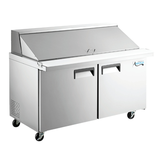
Refrigerated Sandwich Prep Tables
#178APT27HC
27" 1 Door Refrigerated Sandwich Prep Table
#178APT27MHC
27" 1 Door Mega Top Refrigerated Sandwich Prep Table
#178APT48HC
48" 2 Door Refrigerated Sandwich Prep Table
#178APT48MHC
48" 2 Door Mega Top Refrigerated Sandwich Prep Table
#178APT60HC
60" 2 Door Refrigerated Sandwich Prep Table
#178APT60MHC
60" 2 Door Mega Top Refrigerated Sandwich Prep Table
#178APT71HC
71" 3 Door Refrigerated Sandwich Prep Table
#178APT71MHC
71" 3 Door Mega Top Refrigerated Sandwich Prep Table
NOTICE
This manual is for a certified service technician and should not be used by those who are not properly trained.
This manual cannot cover all possible conditions that may occur and is not intended to be all encompassing.
You should read this manual in its entirety and the specific repair you wish to do prior to starting the repair.
This will allow you to determine if you have the correct tools, instruments, and skills to perform the procedure.
REVISED: 05/2022
Service Manual
Advertisement
Table of Contents

Related Manuals for Avantco 178APT27HC


Summary of Contents for Avantco 178APT27HC
- Page 1 Service Manual Refrigerated Sandwich Prep Tables #178APT27HC 27" 1 Door Refrigerated Sandwich Prep Table #178APT27MHC 27" 1 Door Mega Top Refrigerated Sandwich Prep Table #178APT48HC 48" 2 Door Refrigerated Sandwich Prep Table #178APT48MHC 48" 2 Door Mega Top Refrigerated Sandwich Prep Table #178APT60HC 60"...
-
Page 2: Table Of Contents
Evaporator compartment parts..............12 Turn off and disconnect power before servicing ........12 Evaporator fan motors ................12 Evaporator coil ................... 12 Wire Diagram ....................... 14 178APT27HC ....................14 178APT48HC ....................15 178APT60HC ....................16 178APT71HC ....................17 Parts Diagram List ....................18 178APT27HC .................... -
Page 3: Troubleshooting
Troubleshooting Problem Possible Solution Ensure that unit is plugged in Ensure the outlet is correct and dedicated and has power Unit will not turn on Check power switch Check controller Ensure door is properly closed Check door gasket for rips, tears, cut, etc. Ensure all pans are installed on top Ensure ambient air is above 85°F Ensure condenser coil is clean... -
Page 4: Temperature Controller Settings
Temperature Controller Settings 1. To access settings on temperature Mode Setting Display controller, press and hold the "SET" button Temperature Unit F/C until the display flashes with "PS". (Fig. 2) Cabinet Offset 2. Press the "SET" button again to display a Evap Offset blinking "0". - Page 5 Temperature Controller Settings Fig. 4 /C1= Probe 1 differential -50.0° to 50.0°; Default = 0° (Fig. 4) Use up or down arrow to change, then press "Set" button to keep the option. Fig. 5 /C2 = Probe 2 differential (Not used on Refrigerators) (Fig.
- Page 6 Temperature Controller Settings Fig. 9 c0 = Compressor and fan start delay 0 to 100 minutes Default = 2 minutes (Fig. 9) Use up or down arrow to change, then press "Set" button to keep the option. dl = Time between defrosts Fig.
-
Page 7: Part Testing
If amperage is at Locked Rotor Amps, compressor needs replaced. Max Load Locked Rotor Amps Model # Amps (LRA) Fig. 14 178APT27HC 4.5 Amps 16.4 Amps 178APT27MHC 4.5 Amps 16.4 Amps 178APT48HC 6 Amps 18.4 Amps... -
Page 8: Controller
Part Testing Controller Fig. 16 Check for 120 volts between white (N) and black (L) (#4) at the back of the controller. NOTE: there are two black (L) wires. (Fig. 16) With controller calling for compressor to run, check for 120 volts between white (N) and red (Compressor) wire. -
Page 9: Door Seal Heater
Part Testing Door Seal Heater Fig. 19 Disconnect unit from power and unplug red connector, check for 228 Ω at 70°F +/- 10%. (Fig. 19) Check for 120 volts between white and black wires on the red plug at rear of condenser/ compressor compartment. -
Page 10: Condensing Tray Components
Part Replacement Condensing Tray Fig. 24 Fig. 25 Components Compressor 1. Remove Phillips screws holding rear condenser cover in place. (Fig. 24 & 25) 2. Remove 2 Phillips head screws hold condensing tray inside unit. (Fig. 26 & 27) 3. Pull condensing tray out to access Fig. -
Page 11: Filter Drier
Part Replacement Condensing Tray Fig. 32 Components Cont. Filter Drier 11. With condensing tray pulled out, remove by cutting process tube and liquid line to filter. (Fig. 32) 12. Remove from clamp by prying apart clamp clip. 13. With all refrigerant removed from system and a Fig. -
Page 12: Evaporator Compartment Parts
Part Replacement Evaporator Fig. 39 Fig. 40 Compartment Parts Turn off and disconnect power before servicing Evaporator Fan Motors 1. Open doors and remove Phillips screws from brackets holding prep top to base cabinet and screws along back side of unit. (Fig. 39 & 40) Fig. -
Page 13: Evaporator Coil
Part Replacement Evaporator Fig. 47 Fig. 48 Compartment Parts Cont. 9. Rotate inside pan plate and remove from prep table. (Fig. 48) 10. Pull rear pan plate towards the front of the unit to disengage it from the prep top. (Fig. 49) 11. -
Page 14: Wire Diagram
Wire Diagram (178APT27HC) -
Page 15: 178Apt48Hc
Wire Diagram (178APT48HC) -
Page 16: 178Apt60Hc
Wire Diagram (178APT60HC) -
Page 17: 178Apt71Hc
Wire Diagram (178APT71HC) -
Page 18: Parts Diagram List
Parts Diagram List (178APT27HC) - Page 19 Parts Diagram List (178APT27HC) Item # Description Part # Door 17817006HC Door gasket 178GSKT17313 Door cartridge 178CARTRIDGE Lower right hinge 178HINGSCLBR Upper right hinge 178HINGSCLTR Evaporator coil 17812503 Evaporator fan motor 17813407 Standoff bracket - rear 17818837 Controller - temperature 17815350 4 "...
-
Page 20: 178Apt48Hc
Parts Diagram List (178APT48HC) - Page 21 Parts Diagram List (178APT48HC) Item # Description Part # Door - right 17810080HC Door gasket 178GSKT11759 Door cartridge 178CARTRIDGE Lower right hinge 178HINGSCLBR Upper right hinge 178HINGSCLTR Door - left 17810081HC Door gasket 178GSKT11759 Lower left hinge 178HINGSCLBL Upper left hinge 178HINGSCLTL Cutting board bracket 17815972...
-
Page 22: 178Apt60Hc
Parts Diagram List (178APT60HC) - Page 23 Parts Diagram List (178APT60HC) Item # Description Part # Door - right 17819424 Door gasket 178GSKT19722 Door cartridge 178CARTRIDGE Lower right hinge 178HINGSCLBR Upper right hinge 178HINGSCLTR Door - left 17814620 Door gasket 178GSKT19722 Lower left hinge 178HINGSCLBL Upper left hinge 178HINGSCLTL Cutting board bracket 17815972...
-
Page 24: 178Apt71Hc
Parts Diagram List (178APT71HC) - Page 25 Parts Diagram List (178APT71HC) Item # Description Part # Door - right 17810080 Door gasket 178GSKT15178 Door cartridge 178CARTRIDGE Lower right hinge 178HINGSCLBR Upper right hinge 178HINGSCLTR Door - left 17810081 Door gasket 178GSKT15178 Lower right hinge 178HINGSCLBL Upper right hinge 178HINGSCLTL Cutting board bracket 17815972...
Need help?
Do you have a question about the 178APT27HC and is the answer not in the manual?
Questions and answers