
Related Manuals for Seametrics iMAG 4700p


Summary of Contents for Seametrics iMAG 4700p
- Page 1 4700p iMAG 4700p Municipal/Industrial Magmeter Municipal/Industrial Magmeter Instructions Instructions iMAG 4700p 9001...
-
Page 2: Table Of Contents
Things to Try ..................................Page 23 Error Messages ................................Page 23 Warranty Seametrics Limited Warranty ..........................Back Note: These instructions cover the iMAG 4700p For details on the iMAG 4700 or 4700r, see the iMAG 4700 or iMAG 4700r Municipal/Industrial Magmeter Instructions. Seametrics • 253.872.0284 Page 2... -
Page 3: General Information
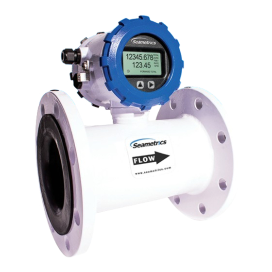
Additionally, high speed digital, and Modbus protocol ® 10 feet (3 meters) continuously. outputs are optional. The iMAG 4700p can be supplied with an optional internal AC power supply. Features User access lid (on back) Data logger port (right... -
Page 4: Specifications
Storage -40˚ to 158˚ F (-40˚ to 70˚ C) Accuracy ±0.75% of reading on iMAG 4700p and 4700r (±1.0% iMAG 4700), ±0.025% of full-scale flow from low flow cutoff to maxi. flow rate of 10 m/sec Low Flow Cutoff 0.5% of maximum flow rate... -
Page 5: Dimensions
GENERAL INFORMATION IMAG 4700p INSTRUCTIONS Dimensions Shipping Weight Bolt Holes iMAG 4700 iMAG 4700p Meter Size inch inch inch inch inch 2” 10.8 15.7 1.76* 12.3 3” 8.35 12.1 15.7 2.68* 15.5 4” 10.12 13.1 15.7 3.12 22.5 6” 12.09 14.9... -
Page 6: Accuracy
GENERAL INFORMATION IMAG 4700p INSTRUCTIONS iMAG Accuracy AG3000 AG3000r & AG3000p (m/s) (ft/s) Flow Velocity 2” & 3” Pressure Drop Note: No pressure drop in 4”-12” meters 3 Inch Pressure Drop 2 Inch Pressure Drop (m/s) (ft/s) Flow Velocity Flow Rate (2” - 12”) Pipe Size 2”... -
Page 7: Installation
INSTALLATION IMAG 4700p INSTRUCTIONS Straight Pipe Recommendations (X = diameter) NOTE: These configurations are to be used as general guidelines and do not cover every possible installation. A combination of two or more obstructions will require additional straight pipe. If there is any concern about the length of pipe required for a specific application, please contact your local dealer. -
Page 8: Full Pipe Recommendations
INSTALLATION IMAG 4700p INSTRUCTIONS Full Pipe Recommendations Recommended: Not Ideal: Keep pipe full at meter for accuracy Allows air pockets to form at meter Recommended: Not Ideal: Keeps pipe full at meter for accuracy Post-valve cavitation can create air pocket... -
Page 9: Positioning The Meter
Straight Pipe Recommendations. The iMAG requires 2. Install Seametrics provided gaskets, or equivilent, straight pipe before and after the meter for best accuracy. on each end of meter as shown in diagrams below. However, the ability of electromagnetic meters to average... -
Page 10: Tightening Flange Bolts
INSTALLATION IMAG 4700p INSTRUCTIONS Tightening Flange Bolts the lock washer fits between the pipe flange and the flange plate. For the best electrical bonding, remove rust and paint NOTE: Mating pipe flanges must be ANSI 150# full face (FF) to expose clean, bare metal where the equalization flange and/or raised face (RT). -
Page 11: Connections
CONNECTIONS IMAG 4700p INSTRUCTIONS General Cable Information In the iMAG 4700p meter, there are a maximum of two The iMAG 4700p is available in either DC or AC versions. Power/Output cables that can be installed. These cables contain the wires for any available outputs (scaled pulse, 4-20mA, Modbus , and Digital) and power (DC or AC). -
Page 12: Cable Installation
CONNECTIONS IMAG 4700p INSTRUCTIONS Cable Installation 1. On the back of the meter, unscrew the black user 15 pin Backup connector access lid and remove it. battery connection Internal AC wires Power supply terminal block (AC versions) 2. Remove the 15 pin screw connector from its bag. -
Page 13: Wiring Diagrams
CONNECTIONS IMAG 4700p INSTRUCTIONS Wiring Diagrams On the back of the meter, unscrew the black user access lid and remove it. Remove the 15 pin screw connector from its bag. Install the wires through the cable glands into the 15 pin screw connector in their respective locations. Plug the 15 pin screw connector into its socket. - Page 14 CONNECTIONS IMAG 4700p INSTRUCTIONS Wiring Diagrams (continued) On the back of the meter, unscrew the black user access lid and remove it. Remove the 15 pin screw connector from its bag. Install the wires through the cable gland into the 15 pin screw connector in their respective locations.
-
Page 15: Cable Wiring Table
CONNECTIONS IMAG 4700p INSTRUCTIONS Wiring Diagrams (continued) Any meter supplied with the Sensus Smart Output option will come with Sensus Smart Output wiring attached to the 15-pin connector. Data logger (RTC) is not an option with the Sensus option. High speed digital output is not available with the Sensus Smart Output option. -
Page 16: Configuration
CONFIGURATION IMAG 4700p INSTRUCTIONS Pulse or Digital Output Application - Sourcing Mode (Recommended for Rin < 30kΩ) Pulse or Digital Output Application - Sinking Mode (Recommended for Rin > 30kΩ) Analog (4-20mA Current Loop) Output Application ** Minimum resistor value is (100 x Vs) ohms. Higher resistances maybe used depending on frequency and cable length. Longer cables and high frequencies require lower resistance. *** Resistor RL converts 4-20mA current to voltage for voltage input only devices. Seametrics • 253.872.0284 Page 16 seametrics.com... -
Page 17: Cable Shield
9600 7200 not exceed the maximum frequency of the meter while also 10800 8100 ensuring a reasonable resolution. The iMAG 4700p has a 12000 9000 maximum pulse output of 200 Hz Lower frequency output pulses (1 pulse for some particular K-factor: Remember that SETP is expressed in units totaled number of gallons) can also be set. -
Page 18: Pulse Output
2.594 5.188 10.38 25.94 51.88 (See Seametrics Modbus Interface Description manual for instructions). The TXD connection is the transmitted data output from the meter and RXD is the received data input to the meter. See Seametric’s Modbus Interface Description, LT-103393 (available at www.seametrics.com) for supported Modbus message protocol and electrical interface specifications. -
Page 19: Operation
OPERATION IMAG 4700p INSTRUCTIONS Changing Flow Meter Settings Making Selections Home Screen and General Navigation The HOME Screen displays flow volume, direction of the Once in the Menu System, move from tab to tab by tapping the right button. (See the next flow total and flow RATE along with status conditions such page for details on the various available tabs.) -
Page 20: Changing Flow Meter Settings - Standard Menu Options
OPERATION IMAG 4700p INSTRUCTIONS Standard Menu Options Note: Available options will depend on specific meter configuration. Not all options are available on all meters. Options not ordered with your meter will not appear on the meter menu. T UNIT SET 4... -
Page 21: To Change A Passcode
OPERATION OPERATION IMAG 4700p INSTRUCTIONS To Change a Passcode and Decimal Places The iMAG has a passcode system for restricting access to • To set the passcode, hold and tap and then use the the menus. The iMAG comes from the factory with the to enter the new code. -
Page 22: Power Indicators
OPERATION IMAG 4700p INSTRUCTIONS Power Indicators A power indicator is displayed in the lower left of the main display window. Being powered by external DC or internal AC Any meter powered from an external power source will display a power plug icon when running on external power. -
Page 23: Troubleshooting & Error Messages
TROUBLESHOOTING & ERROR MESSAGES IMAG 4700p INSTRUCTIONS Troubleshooting Troubleshooting Problem Probable Causes Things to try… Blank Display Faulty wiring from power source to Check for incorrect wiring. Measure voltage with meter DMM where red and black wires connect to terminal block TB1 on back side of display. Verify... -
Page 24: Warranty
The permissible ambient conditions must be adhered to. The information in the relevant documentation must be observed. Trademarks All names identified by ® are registered trademarks of the Seametrics. The remaining trademarks in this publication may be trademarks whose use by third parties for their own purposes could violate the rights of the owner.
Need help?
Do you have a question about the iMAG 4700p and is the answer not in the manual?
Questions and answers