
Related Manuals for Seametrics iMAG


Summary of Contents for Seametrics iMAG
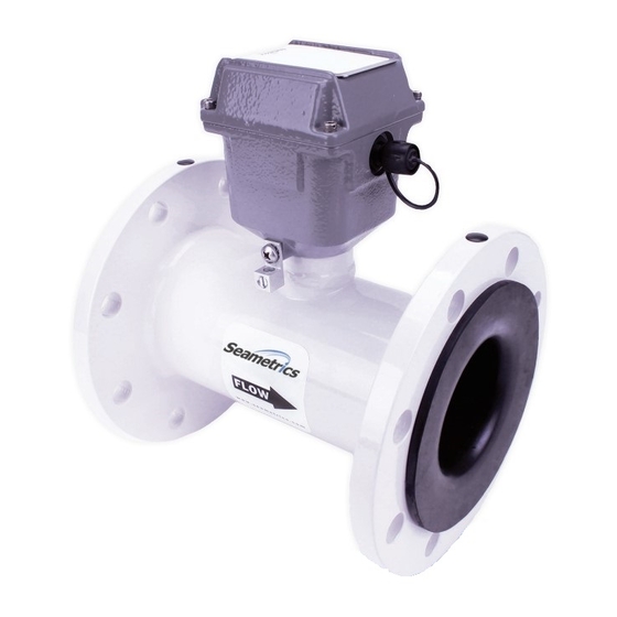
- Page 1 Flow Meters & Controls iMAG Municipal/Industrial Magmeter Instructions 9 0 0 1 : 2 0 0 8 PROUDLY 9 0 0 1 : 2 0 0 8 MADE IN THE CERTIFIED COMPANY CERTIFIED COMPANY...
-
Page 2: Table Of Contents
TABLE OF CONTENTS General Information General Information, Features ......................Page 1 Specifications Specifications, Dimensions, Flow Range ....................Page 3 Installation and Grounding Positioning the Meter, Straight Pipe Recommendations, Full Pipe Recommendations, Fittings, Calibration, Chemical Injection, Installing Gaskets................Page 6 Tightening Flange Bolts, Metal Pipe Installations, Plastic Pipe Installations ........Page 7 Straight Pipe Recommendations ..................... -
Page 3: General Information
This magmeter requires no maintenance in applications where The iMAG 3600 and 4600 can be externally powered with 9-36 debris would impede mechanical meters. There are no parts to Vdc at 30 mA average. The 4600 is also available in a battery wear out. - Page 4 Glass filled molded plastic liner 316SS electrodes (Inside) Flanges, 150 lb. ANSI pattern iMAG 4600 - 300 Rate and total indicator with protective cover and keypad sensors Powder-coated ductile cast iron electronics housing Security seal & cross-drilled screws (2) for tamper-evidence...
-
Page 5: Specifications
IP68 to 10ft (3m) depth *Specifications subject to change. Please consult our website for the most current data (www.seametrics.com). If forward and reverse flow data needs to be sent to another device, either the -ADDX, -DDDX or Modbus output is required. -
Page 6: Flow Range, Accuracy, Dimensions
SPECIFICATIONS DIMENSIONS iMAG4600 - 0300 Shown Cable Exit (Metal Flange) (Including Rubber Gaskets) iMAG3600 Remote Shown .20” Dia. Cable Exit 2.5” 3” 5.62” 4.38” 5.27” iMAG4600 - 0400 to 1200 Shown Cable Exit (Metal Flange) (Including Rubber Gaskets) Page 4... - Page 7 SPECIFICATIONS iMAG Dimensions Shipping iMAG Weight Meter Size inch inch inch inch pounds 3” 12.0 6.80 17.3 2.60 66.04 4” 10.24 8.12 20.9 3.12 79.25 6” 12.27 9.22 23.3 5.05 128.27 8” 14.24 10.22 23.3 6.44 163.58 10” 18.18 11.22 23.3...
-
Page 8: Installation And Grounding
• Inner diameter must be larger than opening in flow Straight Pipe Recommendations. As with most flow meters, meter. the iMAG requires straight pipe before and after the meter for 2. Be sure all mating surfaces are smooth and free of best accuracy. However, the ability of electromagnetic meters debris. -
Page 9: Tightening Flange Bolts, Metal Pipe Installations, Plastic Pipe Installations
Metal Pipe Installations. To equalize the electrical potential • Repeat steps a and b for each bolt in an of the fluid, the iMAG meter, and the surrounding pipe, secure alternating order, such as shown at right, the flange plates (factory-installed on the equalization wire) tightening to 40%, then 60%, then 80%, and then to both pipe flanges at one of the bolt holes, as shown below. -
Page 10: Straight Pipe Recommendations
STRAIGHT PIPE RECOMMENDATIONS (X = diameter) Reduced Pipe iMAG Two Elbows In Plane iMAG Two Elbows, Out Of Plane iMAG Expanded Pipe iMAG Swirling Flow Propeller Meter iMAG Swirling Flow Partially Open iMAG Butterfly Valve Page 8... -
Page 11: Full Pipe Recommendations
FULL PIPE RECOMMENDATIONS Recommended: Keep pipe full at meter for accuracy iMAG iMAG Not Ideal: Allows air pockets to form at meter iMAG iMAG Recommended: Not Ideal: Keeps pipe full at meter for accuracy Post-valve cavitation can create air pocket... -
Page 12: Inputs/Outputs And Operation
1. Before cutting, loosen the cable gland sealing nut and slide 3. Obtain the required additional length of 2-pair Seametrics the gland back past where the cable will be cut. sensor cable and two additional cable glands, installing the 2. -
Page 13: External Power And Wiring
INPUTS/OUTPUTS and OPERATION WIRING TO POWER SOURCES AND EXTERNAL MONITORING AND CONTROL EQUIPMENT 2. Loosen the cable gland sealing nut, remove the plug and insert the unconnected cable end through the open The six-conductor Control Cable exiting the display head hole. -
Page 14: Battery Power, Pulse Output, Analog Output, Hart Communication
(Optional) Setup and Connection to a HART Network. The function of sample period. HART protocol, rev.7.5, allows for a Polling address of 0-63. The default value in the iMAG is 0. To change the Polling Battery Life/Sample Period address, use iMAG menu HPOLL to set the Polling address. -
Page 15: Digital Output, Serial Communication, Cable Control Wiring, K-Factors For High Speed Digital
Selections are: 500Hz and 1, 2, 5 and 10 Modbus Interface Description, LT-103393 (available at www. KHz at maximum flow rate. seametrics.com) for supported Modbus message protocol and electrical interface specifications. Serial Communication Connection. When the second and third OID code characters are “SS”, refer to “Control Cable Wiring”... -
Page 16: Output Applications
INPUTS/OUTPUTS and OPERATION Pulse or Digital Output Application - Sourcing Mode (Recommended for Rin < 30kΩ) Open Current Sourcing Pulse Collector Waveform Transistor Power Green* Source =3-36Vdc White* V Out 47k Ω Pull-down V Out Resistor Meter Cable User Equipment Pulse or Digital Output Application - Sinking Mode (Recommended for Rin >... -
Page 17: Changing Flow Meter Settings
UNIT S FOR DISPLAY Hold Please Note: SET 4 SET 20 SET F EXIT All iMAG meters are factory set for gallons per minute (GPM) rate and gallons total. If other units are required, they can be programmed in the field. Page 15... -
Page 18: Troubleshooting
TROUBLESHOOTING PROBLEM PROBABLE CAUSES Try… Blank Display Faulty wiring from power source to Check for miswiring. Measure voltage with DMM meter or faulty AC power supply where red and black wires connect to terminal block TB2 inside meter display head. Verify cor- rect polarity and confirm that voltage is steady and between 9Vdc and 32Vdc Flow rate reads zero continuously... - Page 19 NOTES Page 17...
- Page 20 S e am e t r ic s In co rpo rat e d • 19 02 6 72n d A ven ue So uth • K e n t , W ashi n gto n 9 8 0 3 2 • USA ( P ) 2 5 3 .8 7 2 .02 84 •...
Need help?
Do you have a question about the iMAG and is the answer not in the manual?
Questions and answers