Table of Contents
Advertisement
Quick Links
Advertisement
Table of Contents

Related Manuals for Satel EASy Pro+


Summary of Contents for Satel EASy Pro+
- Page 1 SATEL-EASy Pro+ radio modem user guide Version 1.6...
-
Page 2: Important Notice
User Guide v.1.6 IMPORTANT NOTICE All rights to this manual are owned solely by SATEL Oy (referred to in this user guide as SATEL). All rights reserved. The copying of this manual (without the written permission from the owner) by... -
Page 3: Restrictions On Use
The allowed max output power depends on the local authority requirements. SATEL-EASy Pro+ is allowed to be used in the following countries, either on licence free channels or on channels where the operation requires a licence. More detailed information is available at the local frequency management authority. - Page 4 SATEL-EASy Pro+ User Guide v.1.6 This device complies with part 15 of the FCC rules. Operation is subject to the following two conditions: (1) This device may not cause harmful interference, and (2) this device must accept any interference received, including interference that may cause undesired operation.
-
Page 5: Product Conformity
User Guide v.1.6 PRODUCT CONFORMITY SATEL Oy hereby declares that SATEL-EASy Pro+ radio modem is in compliance with the essential requirements (radio performance, electromagnetic compatibility and electrical safety) and other relevant provisions of Directive 2014/53/EU. Therefore, the equipment is labelled with the following CE-marking. -
Page 6: Table Of Contents
PRODUCT CONFORMITY ..............................4 WARRANTY AND SAFETY INSTRUCTIONS ....................4 TABLE OF CONTENTS ................................5 PRODUCT INTRODUCTION .............................. 9 SATEL-EASY PRO+ TECHNICAL SPECIFICATIONS ............10 Requlations ................................... 10 General specifications..............................10 Radio spesifications ..............................11 Data modem specifications ..........................13 Default settings ................................ - Page 7 SATEL-EASy Pro+ User Guide v.1.6 RF INTERFACE ..............................28 Transmitter ................................... 28 Receiver ....................................28 Encryption ..................................... 29 Radio state ................................... 30 Priority RX/TX .................................. 30 Forward Error Correction............................30 Error checking ..................................31 5.7.1 SATELLINE-3AS NMS mode ....................... 31 5.7.2 SATELLINE-3AS mode .......................
- Page 8 Features of Message Routing ....................58 11.1.2 Limitations of Message Routing....................58 11.1.3 Getting started with Message Routing with SATEL NETCO DESIGN ........58 11.1.4 SaTerm and the configuration of the Message Routing ............59 11.1.5 Configuration of the protocol in Message Routing ..............60 11.2...
- Page 9 SATEL-EASy Pro+ User Guide v.1.6 13.2.3 General antenna installation instructions ................69 13.3 SATEL-EASy Pro+ grounding ..........................72 13.4 Grounding cable and screws ..........................73 DESIGNING SYSTEMS............................ 74 14.1 Factors affecting the quality and distance of the radio connection ....... 74 14.2...
-
Page 10: Product Introduction
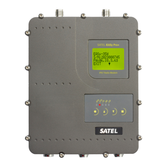
User Guide v.1.6 PRODUCT INTRODUCTION SATEL-EASy Pro+ is an IP67 classified UHF radio modem with a high power (35 W) transmitter, wide 70 MHz tuning range (403...473 MHz) in one hardware and selectable channel spacing. The SATEL-EASy Pro+ can offer radio speeds up to 28.8 kbps and has a selectable serial interface speed between 9600 …... -
Page 11: Satel-Easy Pro+ Technical Specifications
SATEL-EASy Pro+ User Guide v.1.6 SATEL-EASy Pro+ TECHNICAL SPECIFICATIONS Requlations SATEL-EASy Pro+ complies with the following international standards: • EN 300 113 (RF-requirements) • EN 301 489 (EMC-requirements) • EN 62368-1 (Safety Standard) • FCC CFR47 Part 90 (Private Land Mobile Radio Service) -
Page 12: Radio Spesifications
SATEL-EASy Pro+ User Guide v.1.6 Weight IP Classification IP67 Equivalent NEMA6 Dimensions 180.4 x 138.4 x 70.9 Measured under normal ambient conditions, T = +20°C…+25°C. When the device is used in different environment, the results may change significantly. It is recommended to use external ESD protection in demanding conditions. - Page 13 SATEL-EASy Pro+ User Guide v.1.6 typ. 9 4FSK, 25 kHz, FEC ON typ. 9 4FSK, 12.5 kHz, FEC ON typ. 11 CO-Channel Rejection 8FSK, 25 kHz, FEC ON BER = 10 typ. 12 8FSK, 12.5 kHz, FEC ON typ. 23 16FSK, 25 kHz, FEC ON typ.
-
Page 14: Data Modem Specifications
AES128, AES256 AES256 as DRM option Data Formats Asynchronous Default settings SATEL-EASy Pro+ is shipped with the following default settings (unless otherwise specifically agreed): DEFAULT VALUES OF THE ADJUSTABLE SETTINGS (user can change settings later on) Setting Default value Range... - Page 15 SATEL-EASy Pro+ User Guide v.1.6 Tx-Start Delay 0 ms 0-65535 ms Radio Compatibility SATELLINE-3AS See section 6.9, Compatibility modes Encryption* ON/OFF Addressing RX Address ON/OFF TX Address ON/OFF RX addressing to RS port ON/OFF TX address auto switch ON/OFF Serial port 1...
- Page 16 SATEL-EASy Pro+ User Guide v.1.6 When creating a test connection, you can use Windows™ based SATEL NETCO DEVICE (available from SATEL website, www.satel.com), HyperTerminal (which is included in most the Windows™ based operating system packages), or almost any other terminal program.
-
Page 17: Satel-Easy Pro+ Special Features
SATEL-EASy Pro+ SPECIAL FEATURES Call Sign SATEL-EASy Pro+ has a CALL SIGN identifier -feature required in some countries. A call sign can be formally assigned by a government agency, informally adopted by individuals or organizations, or even cryptographically encoded to disguise identity of a station. - Page 18 SATEL-EASy Pro+ User Guide v.1.6 Increasing Temperature Decreasing Temperature Parameter RF Output Power Parameter RF Output Power Temperature Limit 2 +44 dBm (25 W) Temperature Limit 4 +37 dBm (5 W) Temperature Limit 3 +40 dBm (10 W) Temperature Limit 3...
- Page 19 SATEL-EASy Pro+ User Guide v.1.6 It can be recognized decreasing or increasing temperature profiles in the first two figures, the locations where the decreasing occurs mean that the radio has decreased its RF output power for protecting the product from overheating. In the case of increasing temperature after decreasing period, means that the product has increased its RF output power inside the safety limits according to the tables above.
-
Page 20: Input Voltage
PA Voltage Warning Internal RF-PA voltage too low Output power is limited to +37 dBm or high. (5 W). Restart the modem. Contact SATEL technical support if the malfunction still appears after 2- 3 restarts PA Voltage Critical Internal RF-PA voltage critically Transmission is completely low or high. -
Page 21: Lcd User Interface
CD-line active Display and push buttons SATEL-EASy Pro+ includes a LCD (Liquid Crystal Display) with a backlight. In the Data Transfer Mode the display will show the operating settings of the radio modem, for example the radio field strength and the supply voltage. By using the push buttons and the display, it is possible to change most of the settings of the radio modem, without the need for an external terminal. - Page 22 SATEL-EASy Pro+ User Guide v.1.6 The SATEL-EASy Pro+ includes following “LCD Mode” options for the models that are equipped with LCD UI: - Normal (factory default) o Allows the user to read and change the parameters via push buttons and LCD display...
-
Page 23: Lcd Menu Navigation
SATEL-EASy Pro+ User Guide v.1.6 3.2.1 LCD menu navigation Below is a figure for supported menu items and navigation in normal mode. - Page 24 SATEL-EASy Pro+ User Guide v.1.6...
-
Page 25: Surv Menu
SATEL-EASy Pro+ User Guide v.1.6 3.2.2 SURV menu In SURV mode there are considerably less settings that can be changed. In the main screen, the current channel, frequencies, channel spacing and TX power are visible. Note - Asterisk (*) next to the power level means that the active power level is set to be lower than the current channel allows. -
Page 26: Serial Data And Power Interfaces
SERIAL DATA AND POWER INTERFACES SATEL-EASy Pro+ radio modem has two variants: with one serial port or with two serial ports - Port1 and Port2. With two serial port variant one of the ports is configured as the DATA port (by default Port1) that is connected to the user application. -
Page 27: Rs-422 Interface
SATEL-EASy Pro+ User Guide v.1.6 RS-422 interface RS-422 standard defines a serial data transfer method, which is similar to the RS-232 standard. In RS-422 however, the signal lines are differential transmission lines. Differential transmission line is formed by using two signal wires together which are in opposite polarity to each other. Because the state of the signal is defined by the mutual voltage difference (hence the name differential), any common mode disturbances induced into the lines will cancel out. -
Page 28: Port 2 Wiring
SATEL-EASy Pro+ User Guide v.1.6 Port 2 wiring Port 2 (8 pin ODU, GL1LAC-P08LFG0-0000) • DTE is an abbreviation for Data Terminal Equipment • I/O column below denotes the direction of the signal • “IN” is from DTE to the radio modem, “OUT” is from the radio modem to DTE... -
Page 29: Rf Interface
The setting and/or using of non-approved power levels may lead to prosecution. SATEL and its distributors are not responsible for any illegal use of its radio equipment, and are not responsible in any way of any claims or penalties arising from the operation of its radio equipment in ways contradictory to local regulations and/or requirements and/or laws. -
Page 30: Encryption
AES is open source software from public domain. Author: Brian Gladman (U.K). The CTR-mode is SATEL’s in-house implementation. Separate product models from the SATEL radio modem family supports the encryption for the RF interface. The models supporting this feature and encryption level can be viewed in SATEL WEB sites at www.satel.com/products/. -
Page 31: Radio State
Forward Error Correction, FEC-function is switched ON (or OFF) by using NETCO DEVICE, SL- commands or the LCD menu. When activated, the FEC-function will cause the SATEL-EASy Pro+ to automatically add additional error correction information, which increases the amount of transmitted data by 30 %. -
Page 32: Error Checking
When the data is received, the checksum is verified before data is forwarded to the serial port. Options for error checking can be accessed either via SL commands or SATEL NETCO DEVICE (https://www.satel.com/products/software/). Setting must be set equally for all radio modems in the same network. -
Page 33: Separate Rx/Tx-Frequencies
The SATEL-EASy Pro+ can transmit (TX-frequency) and receive (RX-frequency) on separate frequencies. Separate frequencies can be set within the whole tuning range. The frequencies can be set in the display menu or either via SL commands or SATEL NETCO DEVICE (https://www.satel.com/products/software/). When data flow on the TD line starts the frequency shifts from the receiving channel to the transmit channel. - Page 34 “SL@S=x” command selects the compatibility mode, “x” equals the corresponding compatibility option. Example: “SL@S=0” sets the original “SATEL 3AS” compatibility mode (option 0). The modem responds with “OK” message if the requested mode is supported or “ERROR” if the mode is not allowed.
-
Page 35: Configuration By Using Sl Commands
• “5” if the mode is PacCrest-FST • etc. 5.9.3 Settings In order to use the Pacific Crest/TRIMTALK modes implemented in SATEL modems: PACIFIC CREST modems must have: • Protocol Mode • Transparent w/EOT Timeout (when using Pacific Crest modulations) •... - Page 36 255). SATEL modems must have the following key settings: • FEC OFF (because the FEC here means SATEL 3AS FEC, not Pacific Crest/TRIMTALK FEC) • Error check OFF • Radio Compatibility (according to selected Pacific Crest protocol mode setting) When TX address is selected ON, then TX1 address is used like PDL Remote address that is the destination address for the transmitted messages.
- Page 37 FEC bindings (although some previous or special firmware versions differ in the way FEC setting is handled - in case of doubt please contact technical support) Error check and Full CRC16 check must be OFF in SATEL modem SATELLINE RX/TX addressing does not use ARQ scheme like Pacific Crest radios...
-
Page 38: Repeater Function
Pacific Crest PDL modems. Note 2. If error correction is ON (FEC ON) and TRIMTALK mode is activated by using ”SL@S=3” command, the firmware automatically switches SATEL FEC OFF temporarily, and turns it back at the mode return. Note 3. Unlike SATELLINE-3AS and Pacific Crest -compatibility modes, TRIMTALK -compatibility mode doesn’t support acting as a remote station when configured as Repeater (incoming data... -
Page 39: Transparent Data Transmission
TRANSPARENT DATA TRANSMISSION Serial interface, data format The SATEL-EASy Pro+ serial interface uses an asynchronous data format. No external synchronising signal is needed, since necessary timing information is acquired from the start and stop bits transmitted before and after each data field bits (byte). -
Page 40: Cts-Line
6.2.2 CD-line The CD handshaking options are not supported by SATEL-EASy Pro+ modems, the status of the CD-line can only be seen in the CD LED. The options for CD-line are: 1) RSSI-threshold CD is active whenever a signal with a level exceeding the level required for reception exists on the radio channel. -
Page 41: Timing And Delays During Data Transmission
SATEL-EASy Pro+ User Guide v.1.6 3) Reception control RTS-line controls the reception process of the radio modem. An active RTS-line enables reception (as normal). Non-active RTS-line will interrupt reception process immediately, even if the radio modem is receiving a data packet. This option is used to force the radio modem into WAIT State for an immediate channel change. -
Page 42: Tx Delay
In order to match the operation of the radio modem to the user data, the Pause length parameter can be adjusted either by using SL command or SATEL NETCO DEVICE SW program. It may have any value between 3 and 255 characters. The default value is 3 characters. -
Page 43: Test Modes
The recommended data speed at the serial port of the receiving radio modem is 38400 bps @ 25 kHz radio channel or 19200 bps @ 12.5 kHz. The test modes are designed for SATELLINE-3AS, SATEL-8FSK-1, SATEL-8FSK-2, and SATEL- 16FSK-1 radio compatibility modes. -
Page 44: Settings
SATEL NETCO DEVICE SATEL NETCO DEVICE is a software for configuring and reprogramming a SATEL device. The configuration parameters can be read and written from/to the locally connected, powered device. The device configuration can be also created/saved/explored from/to a file without device connection. - Page 45 Channel Spacing (Width) 12.5, 20 or 25 kHz Channel spacing defines the frequency difference between adjacent radio channels. In the context of SATEL-EASy Pro+ modems it also defines the width of the radio channel. Default value: 12.5 kHz Tx Power EASy Pro+ supports transmitter output power levels: 1W, 5W, 10W, 25W and 35W.
- Page 46 SATEL-EASy Pro+ User Guide v.1.6 RX Address See the chapter REPEATER MODE AND ADDRESSING Default value: OFF (Rx Address Disabled) TX Address See the chapter REPEATER MODE AND ADDRESSING Default value: OFF (Tx Address Disabled) RX addressing to RS port...
- Page 47 SATEL-EASy Pro+ User Guide v.1.6 The radio modem recognizes pauses on the serial line and uses Pause length them as criteria for ending the transmission and finding SL commands. The value range is 3….255 bytes. In case the serial port data to be transmitted includes pauses...
- Page 48 SATEL-EASy Pro+ User Guide v.1.6 LCD Mode Normal (factory default) Allows the user to read and change the parameters via push buttons and LCD display Read-only Allows the user to read the parameters from the display but modifying them is possible only via configuration software...
-
Page 49: Commands
Settings can be toggled, SL Commands ON/OFF, CR/LF ON/OFF. In case you need more information on the time delays related to the use of SL commands, please contact the manufacturer. In order to get information of the latest and/or special SL commands please contact SATEL. -
Page 50: Command Mode
SATEL-EASy Pro+ User Guide v.1.6 Command Mode Command mode purpose is separate device normal condition from configure condition. When command mode is active, device is looking for known commands from received data. In this state radio is disabled and therefore no data is transmitted or received by radio. -
Page 51: Repeater Mode And Addressing
In circumstances where it is necessary to extend the coverage area of a radio modem network, SATEL-EASy Pro+ radios can be used as repeater stations. The maximum size of a repeated data packet is 1 kB (kilobyte). The Repeater Function is switched on using NETCO DEVICE, SL commands or the LCD menu. -
Page 52: Addressing
“Message Routing” function in use, Tx / Rx addresses are ignored by the modem. SATEL-EASy Pro+ allows the use of individual addresses both for reception and transmission. Addresses can be switched on separately, or simultaneously, in both data transfer directions. - Page 53 SATEL-EASy Pro+ User Guide v.1.6 Transmission: Address Data Data Data Data Transmission address has been set OFF. Transmission addressing has been set ON. Radio modem will transmit the data packet The radio modem will add the primary TX as such.
-
Page 54: Connection Between Two Points
SATEL-EASy Pro+ User Guide v.1.6 Data Address Data Data Data Address Data Reception addressing has Reception addressing has Reception addressing been set OFF. been set OFF. been set ON but there is no address in the data packet. The radio modem will... -
Page 55: Using Repeaters And Addresses In The Same System
SATEL-EASy Pro+ User Guide v.1.6 a message by adding the address of the corresponding radio modem into the beginning of the data packet. The substation radio modem(s) will check the address and the corresponding radio modem will identify and remove the address characters. In a similar way, the substation will add when transmitting to the base station its address characters into the beginning of the data packet, thus defining the origin of the sent data packet. -
Page 56: Repeater Chain Using Address Pairs
SATEL-EASy Pro+ User Guide v.1.6 - The above is the same message after being relayed from the last repeater in the chain (repeater 2) to the substation. DATA - The above is the same message being relayed via the serial interface of the substation radio modem to the terminal device. -
Page 57: Repeater Chain Using Dual Addressing
SATEL-EASy Pro+ User Guide v.1.6 10.3.3 Repeater chain using dual addressing If the terminal devices cannot add address chains to the beginning of the data packets, a network with several repeaters may still be realised by using dual addressing. In dual addressing each link (see arrows below in figure) is given a unique address, which will prevent duplication of messages and endless loops in the network. -
Page 58: Message Routing
MESSAGE ROUTING 11.1 Introduction to Message Routing Message Routing is an exciting feature in SATEL-EASy Pro+. This feature allows messages from terminal devices to be automatically routed over the radio modem network to a specified recipient terminal. In brief, the Message Routing works as follows: •... -
Page 59: Features Of Message Routing
User Guide v.1.6 11.1.1 Features of Message Routing The Message Routing feature of the SATEL-EASy Pro+ is designed to be a fast and transparent to fit real time systems. The features include: • Transparent to user protocols. • Easy construction of a network containing several repeaters. -
Page 60: Saterm And The Configuration Of The Message Routing
SATEL-EASy Pro+ User Guide v.1.6 2. Configure the radio modems accordingly. There are two ways to configure the parameters related to the Message Routing: • SaTerm PC-program • Manual configuration in the setup menu. In either case, please check the chapter on Settings before changing the setup of the radio modems. -
Page 61: Configuration Of The Protocol In Message Routing
SATEL-EASy Pro+ User Guide v.1.6 11.1.5 Configuration of the protocol in Message Routing A radio modem will detect the presence of an address used by inspecting the protocol from the message received via the serial interface. On the basis of this user address, all necessary information needed to relay the message to destination is fetched from an internal routing table inside a radio modem. -
Page 62: Detailed Description Of Source Routing
SATEL-EASy Pro+ User Guide v.1.6 11.2 Detailed description of Source Routing System Modem 1, 2 1, 3 The above figure represents a network containing four (4) radio modems. Each radio modem is given a unique address (0…3). A terminal device has been attached to the three of the four radio modems and they communicate with each other using terminal addresses X, Y and Z, respectively. -
Page 63: Overhop Function In 3As Source Mode Routing
SATEL-EASy Pro+ User Guide v.1.6 11.2.1 Overhop function in 3AS Source Mode Routing M a s t e r Ra d i o M a s t e r Su b s t a t i o n RD When using repeaters, the same packet is sent via a (radio) channel several times. A radio modem situated in the repeater chain will often hear other radio modems in addition to the immediate neighbouring radio modems. -
Page 64: Network Id
SATEL-EASy Pro+ User Guide v.1.6 The overhop function allows for the use of mobile substations. In the example above, a mobile substation is first located in the coverage area of repeater R2. The route is defined as M, R1, R2 and vehicle. -
Page 65: Nms Network Management System
More information is provided by the SATEL NMS PC user manual and application notes. Figure 1.2 A typical screenshot of SATEL NMS PC software. (Routing view). In order to get the SATEL NMS PC software please contact your local SATEL distributor or SATEL headquarters in Finland. -
Page 66: System Components
12.1 How to add SATEL-EASy Pro+ to SATELLINE-3AS NMS network Since the SATEL-EASy Pro+ factory settings (serial port as well as the radio settings) are always the same, those should be set first as in the existing radio network to avoid conflicts. -
Page 67: Nms - Usage
Adding a new SATEL-EASy Pro+ modem to SATELLINE-3AS NMS network: Due to the settings of the SATEL-EASy Pro+ modem, the new modem to network must be add in the SATEL NMS PC software Design menu with the function “Add modem using hardware” and then follow the requests in the to-do list. -
Page 68: Requirements For The User System
The designing of any radio modem system requires very precise planning. Once the choices between devices, their locations, installation, maintenance etc. are clear, the project file for the system can be implemented by using SATEL NMS PC software. Please refer to the SATEL NMS PC User Guide for more detailed description. -
Page 69: Installation
13.1.1 Fuse A proper fuse must be connected in between the radio modem and the power supply. The correct value is 20 A for SATEL-EASy Pro+. 13.1.2 Power supply The allowed operating voltage is +9 ... +30 VDC. The radio modem must only be connected to a power supply with an adequate current output (power rating minimum is typically 105 W @ +45.4... -
Page 70: Antenna Installation
SATEL-EASy Pro+ User Guide v.1.6 13.2 Antenna installation NOTE! Because of the great transmission power of SATEL-EASy Pro+ radio modem, only an external antenna is allowed. A whip-antenna directly connected to the antenna connector must not be used. 13.2.1 Mobile equipment •... - Page 71 SATEL-EASy Pro+ User Guide v.1.6 must withstand all foreseeable weather conditions (frost, excess sun, direct UV-radiation, seawater etc.). Also possible environmental pollution must be considered (acids, ozone etc.). Antennas must be installed well away from metallic objects. In the case of small antennas this distance should be at least ½...
- Page 72 SATEL recommends the use of a band-pass filter with a large Q in the antenna cable of the base station.
-
Page 73: Satel-Easy Pro+ Grounding
Ter m i n al 13.3 SATEL-EASy Pro+ grounding SATEL-EASy Pro+ is equipped with a grounding terminal, as shown below. It is recommended to connect a ground wire from the grounding terminal to the earth ground and that all other... -
Page 74: Grounding Cable And Screws
SATEL-EASy Pro+ User Guide v.1.6 13.4 Grounding cable and screws Grounding cable should be with >1 mm copper conductor with insulation, preferable green/yellow coded for easy ground recognition. Cable should be joined to grounding connector by crimp connection (pictured). Grounding should be terminated to a grounding rail or other reliable grounding source with shortest possible cable length to avoid ground loops and elevated resistances in cables. -
Page 75: Designing Systems
• interference caused by other electrical equipment The transmitter power of the SATEL-EASy Pro+ is 35W (maximum) and the sensitivity of the receiver better than -110 dBm. Thus in a flat area and in free space with a 1/4 wave antenna (antenna amplification 1 dBi) and antenna height of 1m communication distances of 3 to 4km can be achieved. -
Page 76: Radio Field Strength
SATEL-EASy Pro+ User Guide v.1.6 A sufficient safety margin can be obtained by testing the communication path using extra 6 dB attenuation at the antenna connection and with slightly less effective antennas than those to be used in the final system. -
Page 77: Check List
SATEL-EASy Pro+ User Guide v.1.6 CHECK LIST The following points must be taken into account when installing and configuring a radio modem: All operating voltages of all the equipment concerned must always be switched OFF before connecting the serial interface cable. -
Page 78: Accessories
ODU 2-pin male, C14 male IEC power inlet. IN, 100-240 Vac, OUT 12 Vdc / 12.5 A YC0904 Mains cable C-M With Europlug for YP1150 Contact SATEL Oy for more detailed information about other serial interface cable options. 16.2 Power cable Product code Type Description YC2957... -
Page 79: Antennas
If a station is installed to a location exposed to lightning, it is recommended to insert a lightning protector to the feed-line outside the protected zone. SATEL Technical Support can give guidance in the selection of suitable products. - Page 80 SATEL-EASy Pro+ User Guide v.1.6 APPENDIX A ASCII CHARACTER TABLE NUL 43 2B 129 81 172 AC 215 D7 SOH 44 2C 130 82 173 AD 216 D8 45 2D 131 83 174 AE 217 D9 46 2E 132 84...
-
Page 81: Transmission Related Delays
SATEL-EASy Pro+ User Guide v.1.6 18. APPENDIX B 18.1 Transmission related delays Delay from the end of transmission to the end of reception on the serial interface: 18.1.1 Transmission delays when the radio TX frequency is changed • If the modem’s transmitter frequency (TX) is different than the receiver frequency (RX), there has to be at least 20 ms delay from the Receive Data (RD) to Transmit Data (TD). - Page 82 User Guide v.1.6 SATELLINE-3AS, 12.5 kHz, FEC ON Number of bytes Data rate/bps 9600 19200 38400 57600 115200 SATEL-8FSK-1, 12.5 kHz, FEC OFF Number of bytes Data rate/bps 9600 19200 38400 57600 115200 SATEL-8FSK-2, 12.5 kHz, FEC ON Number of...
-
Page 83: Transmission Delays Using A 25 Khz Radio Channel
57600 115200 SATELLINE-3AS, 25 kHz, FEC ON Number of bytes Data rate/bps 9600 19200 38400 57600 115200 SATEL-8FSK-1, 25 kHz, FEC OFF Number of bytes Data rate/bps 9600 19200 38400 57600 115200 SATEL-8FSK-2, 25 kHz, FEC ON Number of bytes... - Page 84 SATEL-EASy Pro+ User Guide v.1.6 SATEL-16FSK-1, 25 kHz, FEC ON Number of bytes Data rate/bps 9600 19200 38400 57600 115200...
-
Page 85: Dimensions, Satel-Easy Pro
SATEL-EASy Pro+ User Guide v.1.6 19. APPENDIX C 19.1 Dimensions, SATEL-EASy Pro+ The device physical dimensions and the holes in millimetres. The dimensions of 1- and 2-serial port versions are the same. - Page 86 SATEL-EASy Pro+ User Guide v.1.6...
- Page 87 SATEL-EASy Pro+ User Guide v.1.6 1-serial port model 2-serial port model The device physical dimensions and the holes in millimetres with wall mount parts (WP0135).
-
Page 88: Version History
SATEL-EASy Pro+ User Guide v.1.6 20. VERSION HISTORY Version history: Version: Date: Remarks: 11.07.2022 First official version 11.08.2022 Added information of grounding, chapters 13.3 and 13.4 8.11.2022 FCC regulatory information added, grounding screw type corrected. 28.11.2022 Safety distance table updated 01.02.2023...
Need help?
Do you have a question about the EASy Pro+ and is the answer not in the manual?
Questions and answers