Satel SATELLINE-3ASd Epic Pro 35W User Manual
Hide thumbs
Also See for SATELLINE-3ASd Epic Pro 35W:
- Manual (60 pages) ,
- Product info (2 pages) ,
- User manual (116 pages)
Table of Contents
Advertisement
Quick Links
Download this manual
See also:
Manual
SATELLINE-3ASd Epic Pro and Epic Pro 35W
User guide version 1.4
IMPORTANT NOTICE
All rights to this manual are owned solely by SATEL OY (referred to in this user guide as SATEL).
All rights reserved. The copying of this manual (without the written permission from the owner) by
printing, copying, recording or by any other means, or the full or partial translation of the
manual to any other language, including all programming languages, using any electrical,
mechanical, magnetic, optical, manual or other methods or devices is forbidden.
SATEL reserves the right to change the technical specifications or functions of its products, or to
discontinue the manufacture of any of its products or to discontinue the support of any of its
products, without any written announcement and urges its customers to ensure, that the
information at their disposal is valid.
SATEL software and programs are delivered "as is". The manufacturer does not grant any kind
of warranty including guarantees on suitability and applicability to a certain application. Under
no circumstances is the manufacturer or the developer of a program responsible for any
possible damages caused by the use of a program. The names of the programs as well as all
copyrights relating to the programs are the sole property of SATEL. Any transfer, licensing to a
third party, leasing, renting, transportation, copying, editing, translating, modifying into another
programming language or reverse engineering for any intent is forbidden without the written
consent of SATEL.
SATEL PRODUCTS HAVE NOT BEEN DESIGNED, INTENDED NOR INSPECTED
TO BE USED IN ANY LIFE SUPPORT RELATED DEVICE OR SYSTEM RELATED
FUNCTION NOR AS A PART OF ANY OTHER CRITICAL SYSTEM AND ARE
GRANTED NO FUNCTIONAL WARRANTY IF THEY ARE USED IN ANY OF THE
APPLICATIONS MENTIONED.
Salo, FINLAND 2010
Copyright: 2010 SATEL Oy
No part of this document may be reproduced, transmitted or stored in a retrieval system in any form or by any means without the prior
written permission of SATEL Oy. This document is provided in confidence and must not be distributed to third parties without the express
permission of SATEL Oy.
1
Advertisement
Table of Contents

Related Manuals for Satel SATELLINE-3ASd Epic Pro 35W


Summary of Contents for Satel SATELLINE-3ASd Epic Pro 35W
-
Page 1: Important Notice
No part of this document may be reproduced, transmitted or stored in a retrieval system in any form or by any means without the prior written permission of SATEL Oy. This document is provided in confidence and must not be distributed to third parties without the express... -
Page 2: Restrictions On Use
User guide version 1.4 RESTRICTIONS ON USE SATELLINE-3ASd Epic Pro is allowed to be use in the following countries, either on licence free channels or on channels where the operation requires a licence. More detailed information is available at the local frequency management authority. -
Page 3: Product Conformity
PRODUCT CONFORMITY SATELLINE-3ASd Epic Pro Hereby, SATEL Oy declares that SATELLINE-3ASd Epic Pro radio modem is in compliance with the essential requirements (radio performance, electromagnetic compatibility and electrical safety) and other relevant provisions of Directive 1999/5/EC. Therefore the equipment is labelled with the following CE-marking. - Page 4 SATELLINE-3ASd Epic Pro and Epic Pro 35W User guide version 1.4 SATELLINE-3ASd Epic Pro 35W Hereby, SATEL Oy declares that SATELLINE-3ASd Epic Pro 35W conforms to the requirements of Code of Federal Regulations, Title 47, Part 90 (Federal Communications Commission, FCC).
-
Page 5: Table Of Contents
TABLE OF CONTENTS.................... 5 INTRODUCTION....................10 1 SATELLINE-3ASD EPIC PRO TECHNICAL SPECIFICATIONS ......11 2 SATELLINE-3ASD EPIC PRO 35 W TECHNICAL SPECIFICATIONS....12 2.1 Basic configuration and installation............13 3 OTHER FEATURES ..................14 4 SATELLINE-3ASD EPIC PRO 35W SPECIAL FEATURES ........15 4.1 Call Sign ..................... - Page 6 ..................25 6.3 Programming..................... 26 6.3.1 Power level change by using the LCD and keypad ........... 26 6.3.2 SATELLINE-3ASd Epic Pro/ Epic Pro 35W LCD DISPLAY AFTER POWER-UP....27 7 RF INTERFACE ....................28 7.1 Transmitter....................28 7.2 Receiver...................... 29 7.3 Priority RX/TX.....................
- Page 7 SATELLINE-3ASd Epic Pro and Epic Pro 35W User guide version 1.4 9.3.1 Data buffering in the radio data modem..............39 9.3.2 Pause length ......................40 9.3.3 TX delay....................... 41 9.4 Tests ....................... 41 10 REPEATER MODE AND ADDRESSING............43 10.1 Repeater ....................43 10.2 Addressing ....................
- Page 8 SATELLINE-3ASd Epic Pro and Epic Pro 35W User guide version 1.4 12.1.8 Restoring factory settings ..................71 12.1.9 Saving modified settings into the permanent memory ..........71 12.1.10 Updating software .................... 72 12.1.11 Saving modified values into the internal memory ..........72 12.2 Changing parameters using the SL-COMMANDS........
- Page 9 SATELLINE-3ASd Epic Pro and Epic Pro 35W User guide version 1.4 18.1 Functional delays ..................92 18.2 Transmission related delays..............92 18.2.1 Transmission delays when using a 12.5 kHz radio channel........93 18.2.2 Transmission delays using a 25 kHz radio channel ..........95...
-
Page 10: Introduction
FEC-method (Forward Error Correction). FEC can be used to minimise errors caused by noisy channels. SATELLINE-3ASd Epic Pro and Epic Pro 35W radio modem operates in one of the 4 basic modes of operation: Data Transfer Mode, Programming Mode, Test Mode or Standby Mode. -
Page 11: Satelline-3Asd Epic Pro Technical Specifications
SATELLINE-3ASd Epic Pro and Epic Pro 35W User guide version 1.4 SATELLINE-3ASd Epic Pro technical specifications SATELLINE-3ASd Epic Pro (370…470 MHz) complies with the following international standards: EN 300 113-1,-2 (RF), EN 301 489-1,-5 (EMC), EN 60950-1 (Safety) and FCC CRF47 part 90. RADIO TRANSCEIVER Frequency Range 370...470 MHz... -
Page 12: Satelline-3Asd Epic Pro 35 W Technical Specifications
SATELLINE-3ASd Epic Pro and Epic Pro 35W User guide version 1.4 SATELLINE-3ASd Epic Pro 35 W technical specifications SATELLINE-3ASd Epic Pro 35W (400…470 MHz) complies with the following international standard: FCC CFR47 part 90. RADIO TRANSCEIVER Frequency / Tuning Range 400...470 MHz / 2 x 2 MHz... -
Page 13: Basic Configuration And Installation
Radio Settings TX power 10 W (35 W for Epic Pro 35W) / Signal threshold -112 dBm (25 kHz) or -114 dBm (12.5 kHz) / FCS OFF / Compatibility Satel 3AS / Call sign OFF (Tx output options are 1, 2, 5, 10 W (Epic Pro) and 5, 10, 20, 25, 35 W (Epic Pro 35W)). -
Page 14: Other Features
User guide version 1.4 3 OTHER FEATURES SATELLINE-3ASd Epic Pro and E E pic Pro 35W radio modems fulfil the IP67 (NEMA 6) standard. With an IP67 rating a product will be totally protected against dust and remain completely sealed when immersed in water to a depth between 15 cm and 1 meter. -
Page 15: Satelline-3Asd Epic Pro 35W Special Features
SATELLINE-3ASd Epic Pro and Epic Pro 35W User guide version 1.4 4 SATELLINE-3ASd EPIC PRO 35W SPECIAL FEATURES Sign 4.1 Call Epic Pro 35W has a CALL SIGN identifier -feature required in some countries. A call sign can be formally assigned by a government agency, informally adopted by individuals or organizations, or even cryptographically encoded to disguise identity of a station. -
Page 16: Temperature Protection Of Rf Power Amplifier
SATELLINE-3ASd Epic Pro and Epic Pro 35W User guide version 1.4 4.2 Temperature protection of RF power amplifier RF power amplifier is protected against overheating. The power of transmitter is lowered step by step if the inner temperature exceeds certain levels as shown below. -
Page 17: Protection Of Current
4.4 Pacific Crest and TRIMTALK compatibility 4.4.1 General SATELLINE-3ASd Epic Pro and Epic Pro 35W radio modems support additional to the original SATEL 3AS data transfer also: o Pacific Crest compatible data transfer over the air, if the opponent Pacific Crest modems operate in the transparent mode/FEC ON/Scrambling ON that is the most common setup among RTK applications. -
Page 18: Configuration By Using Sl Commands
RX1 address matches the Remote Address of a Pacific Crest transmitter (or if the message has the broadcast address 255). SATELLINE modems must have the following key settings: o FEC OFF (because the FEC here means SATEL 3AS FEC, not Pacific Crest/TRIMTALK FEC ) o Error check OFF... - Page 19 SATELLINE-3AS and SATELLINE-M3 radio modems are configured via the serial port using any ordinary terminal program or SATEL Configuration Manager PC-program. The table on the next page shows the analogy of settings between Pacific Crest and SATELLINE...
- Page 20 SATELLINE-3ASd Epic Pro and Epic Pro 35W User guide version 1.4 The table shows the analogy of the settings between Pacific Crest and SATEL radio modems. Pacific Crest setting Corresponding SATELLINE-3AS setting (status in software version 3.35) Identification: Call Sign...
-
Page 21: Repeater Function
Diversity setting must be OFF. Note 3. If error correction is ON (FEC ON) and TRIMTALK mode is activated by using ”SL@S=3” command, the firmware automatically switches SATEL FEC OFF temporarily, and turns it back at the mode return. -
Page 22: Latency
SATELLINE-3ASd Epic Pro and Epic Pro 35W User guide version 1.4 4.4.7 Latency In the PCC Transparent protocol mode (Option 1 and Option 2) the whole message is first read from the serial port and after that it will be framed and transmitted over the radio. -
Page 23: Serial Interface
The radio modem is referred to as DCE (Data Communication Equipment) whereas the PC is referred to as DTE (Data Terminal Equipment). SATELLINE-3ASd Epic Pro radio modem includes a Lemo compatible 8-pin, Epic Pro 35 W includes a 7-pin ODU MINI –Snap Style G4 Size 0 (or 8 pin LEMO HGA) which contains all the connections required to establish communication between the radio modem, acting as the DCE, and the PC, acting as the DTE. -
Page 24: Connectors
Not connected Not connected 2. Power connector SATELLINE-3ASd Epic Pro 35W 4 pin ODU MINI-SNAP Style G4 size 1 PWR (+) PWR (+) NOTE! SATELLINE-3ASd Epic Pro does not have a separate power connector. Power is fed via data connector. -
Page 25: Programming
SATELLINE-3ASd Epic Pro and Epic Pro 35W User guide version 1.4 6 Programming 6.1 Display ö Field strength indicator. Shows how strong is the received signal. For example: -80 (dBm) Modem turns to show noise level ~7 sec. after the latest message reception. -
Page 26: Programming
SATELLINE-3ASd Epic Pro and Epic Pro 35W User guide version 1.4 6.3 Programming Full programming is done in “programming mode”. The radio modem will switch into the programming mode by connecting the Mode pin to the ground. This is easily done by using the NARS-ST adapter cable together with the NARS-1F-4A interface adapter. -
Page 27: Satelline-3Asd Epic Pro/ Epic Pro 35W Lcd Display After Power-Up
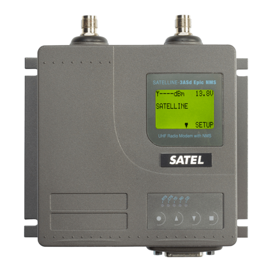
SATELLINE-3ASd Epic Pro and Epic Pro 35W User guide version 1.4 6.3.2 SATELLINE-3ASd Epic Pro/ Epic Pro 35W LCD DISPLAY AFTER POWER-UP Field strength Supply voltage / of the last battery level received indicator transmission or n n oise Display in Data N-120 12.1V... -
Page 28: Rf Interface
User guide version 1.4 RF INTERFACE The SATELLINE-3ASd Epic Pro and Epic Pro 35 W have a single TNC type connector with impedance of 50 When ordering the radio modem, the frequency band to which the radio modem will be tuned to at the factory must be defined. -
Page 29: Receiver
Priority RX/TX SATELLINE-3ASd Epic Pro and Epic Pro 35 W offer a Priority setting, which selects the priority between reception and transmission. The setting can be changed in Programming Mode. By default, transmission has higher priority than reception i.e. the default value is Priority TX. -
Page 30: Error Correction
User guide version 1.4 Error correction Another feature of the SATELLINE-3ASd Epic Pro and Epic Pro 35W is the addition of an error correction mode called the FEC method (F F orward E E rror C C orrection). FEC function is switched ON (or OFF) by using the Programming Mode. -
Page 31: Dual Band Feature And Dual Channel Function
User guide version 1.4 Dual Band feature and Dual Channel function SATELLINE-3ASd Epic Pro and Epic Pro 35W radio modems have a special "Dual Band" feature. The radio transceiver offers two times two MHz frequency bands, and radio modem can be reprogrammed to operate at any channel within those two bands. -
Page 32: Free Channel Scan (Fcs) Function
The FCS function is supported starting from the software version 3.07. To make the use easier SATEL provides the FCS terminal software for your PC. By using the program it is easy to configure the radio modems to use the FCS function. There is also a scanning tool for measuring the power level of the selected radio channels. - Page 33 SATELLINE-3ASd Epic Pro and Epic Pro 35W User guide version 1.4 A screen snapshot of the FCS terminal software below:...
-
Page 34: User Interface
SATELLINE-3ASd Epic Pro and Epic Pro 35W User guide version 1.4 8 USER INTERFACE LED-indicators There are five (5) LED indicators on the front panel of the radio modem, and they give an indication of the status of the serial port and the radio interface:... -
Page 35: Changing The Settings (Example: Epic Pro 35W)
SATELLINE-3ASd Epic Pro and Epic Pro 35W User guide version 1.4 In the Programming Mode, the radio modem will use serial port P P ORT1, with settings 9600 bps, N, 8,1 (data transfer speed 9600 bps, no parity, 8 data bits and 1 stop bit). For more detailed instructions for changing each setting, see Chapter 7.2.1. -
Page 36: Restoring Factory Settings
SATELLINE-3ASd Epic Pro and Epic Pro 35W User guide version 1.4 8.2.2 Restoring factory settings Selecting menu selection “A” may restore factory settings. Enter selection >A Restore factory settings ------------------------ Do you want to restore factory settings? (Y/N)> Factory settings are restored by selecting ”Y” (YES). By pressing any other button current settings will remain active. -
Page 37: Transparent Data Transmission
SATELLINE-3ASd Epic Pro and Epic Pro 35W User guide version 1.4 TRANSPARENT DATA TRANSMISSION Serial interface, data format The S S ATELLINE-3ASd Epic Pro and E E pic Pro 35 W radio modem serial interface uses an asynchronous data format. No external synchronising signal is needed, since necessary timing information is acquired from the start and stop bits transmitted before and after each data field bits (byte). -
Page 38: Handshake Lines
SATELLINE-3ASd Epic Pro and Epic Pro 35W User guide version 1.4 Handshake lines When using the RS-232 serial interface, handshake signals can be used to control data transfer. Handshake signals are used, for example, by the radio modem to inform the terminal that the radio channel is busy, and that it cannot initiate transmission. -
Page 39: Rts-Line
SATELLINE-3ASd Epic Pro and Epic Pro 35W User guide version 1.4 2) D D ata on channel CD will switch to active state only after recognition of a valid data transmission. CD will not react to interference signals. 3) A A lways ON CD is always in the active state. -
Page 40: Pause Length
SATELLINE-3ASd Epic Pro and Epic Pro 35W User guide version 1.4 and after all buffered data has been transmitted. When the serial interface speed is the same or slower than the speed of the radio interface, the internal transmit buffer memory cannot overflow. -
Page 41: Tx Delay
SATELLINE-3ASd Epic Pro and Epic Pro 35W User guide version 1.4 9.3.3 TX delay The radio modem can be configured to delay the beginning of a radio transmission by 1...65000 ms. This function can be used to prevent packet contention in a system, where all substations would otherwise answer a poll of a base-station simultaneously. - Page 42 SATELLINE-3ASd Epic Pro and Epic Pro 35W User guide version 1.4 Example of a long data blocks: This is a long testline of SATELLINE-3AS radio modem This is a long testline of SATELLINE-3AS radio modem This is a long testline of SATELLINE-3AS radio modem The strength of the received signal can be monitored using the LCD-display of the receiving radio modem.
-
Page 43: Repeater Mode And Addressing
In circumstances where it is necessary to extend the coverage area of a radio modem network, SATELLINE-3ASd Epic Pro and Epic Pro 35W radio modems can be used as repeater stations. The maximum size of a repeated data packet is 1kB (kilobyte). The Repeater Function is switched on using the Programming Mode. -
Page 44: Addressing
“Message Routing” function in use, Tx / Rx addresses are ignored by the modem software. SATELLINE-3ASd Epic Pro and Epic Pro 35W radio modem allows the use of individual addresses both for reception and transmission. Addresses can be switched on separately, or simultaneously, in both data transfer directions. - Page 45 SATELLINE-3ASd Epic Pro and Epic Pro 35W User guide version 1.4 Transmission: Transmission address has been set OFF. Transmission addressing has been set Radio modem will transmit the data ON. The radio modem will add the packet as such. primary TX address to the beginning of the data packet.
-
Page 46: Connection Between Two Points
SATELLINE-3ASd Epic Pro and Epic Pro 35W User guide version 1.4 Reception addressing has Reception addressing Reception addressing been set OFF. been set OFF. been set ON but there is no address in the data packet. The radio modem will... -
Page 47: Using Repeaters And Addresses In The Same System
SATELLINE-3ASd Epic Pro and Epic Pro 35W User guide version 1.4 For example, if the substation terminal devices are not able to check and form addresses by themselves, addressing may be achieved with the help of the addresses of the radio modems attached to these terminal devices. -
Page 48: Repeater Chain Using Address Pairs
SATELLINE-3ASd Epic Pro and Epic Pro 35W User guide version 1.4 S ADD DATA - The above is the same message after being relayed from the last repeater in the chain (repeater 2) to the substation. DATA - The above is the same message being relayed via the serial interface of the substation radio modem to the terminal device. -
Page 49: Repeater Chain Using Dual Addressing
SATELLINE-3ASd Epic Pro and Epic Pro 35W User guide version 1.4 10.3.3 Repeater chain using dual addressing If the terminal devices cannot add address chains to the beginning of the data packets, a network with several repeaters may still be realised by using dual addressing. In dual addressing each link (see arrows below in figure) is given a unique address, which will prevent duplication of messages and endless loops in the network. -
Page 50: Message Routing
Introduction to Message Routing 11.1 Message Routing is an exciting feature in SATELLINE-3ASd Epic Pro and Epic Pro 35W. This feature allows messages from terminal devices to be automatically routed over the radio modem network to a specified recipient terminal. -
Page 51: Features Of Message Routing
User guide version 1.4 11.1.1 Features of Message Routing The Message Routing feature of the SATELLINE-3ASd Epic Pro and Epic Pro 35W is designed to be a fast and transparent to fit real time systems. The features include: o Transparent to user protocols. -
Page 52: Getting Started With Message Routing
SATELLINE-3ASd Epic Pro and Epic Pro 35W User guide version 1.4 11.1.3 Getting started with Message Routing The design of any radio modem system requires very precise planning. Once the choices between devices, their location, installation, maintenance etc. are clear, the Message Routing for the system can be implemented. -
Page 53: Manual Configuration Of The Message Routing
SATELLINE-3ASd Epic Pro and Epic Pro 35W User guide version 1.4 11.1.5 Manual configuration of the Message Routing The radio modems can be configured manually via the programming menu. However, this is recommended only if the structure of the network is very simple, or if it is desirable to define such special functions that are not possible to draw using the graphical interface of SaTerm. -
Page 54: Operating Modes Of Message Routing
SATELLINE-3ASd Epic Pro and Epic Pro 35W User guide version 1.4 Operating modes of Message Routing 11.2 The Message Routing has two different operating modes: o Source Mode Routing o Virtual Mode Routing The most important differences between the two modes are shown in the table below. -
Page 55: Detailed Description Of Message Routing
The address information received together with the packet is reversed (2, 1, 0) and saved to be use in the transmission of subsequent reply packets. 11.3.2 Virtual Mode Routing Please contact SATEL for more information of Virtual Mode Routing. 11.3.3 Overhop function in Source Mode Routing... - Page 56 SATELLINE-3ASd Epic Pro and Epic Pro 35W User guide version 1.4 When using repeaters, the same packet is sent via a (radio) channel several times. A radio modem situated in the repeater chain will often hear other radio modems in addition to the immediate neighbouring radio modems.
-
Page 57: Network Id
SATELLINE-3ASd Epic Pro and Epic Pro 35W User guide version 1.4 picks the packet already from the transmission of R1. This is then transferred to the serial port using an additional delay, so that the timing does not differ from the first situation where the radio modem of the vehicle was in the coverage area of repeater R2. -
Page 58: Settings
User guide version 1.4 12 SETTINGS The configuration of SATELLINE-3ASd Epic Pro radio modems can be easily changed. Simply by connecting pin 1 (7-pin. version) or 6 (8-pin. version) to ground (GND) the radio modem will switch into Programming Mode. -
Page 59: Changing Frequency (Active Radio Channel Frequency)
SATEL is not responsible for any illegal use practiced with any devices manufactured and/or sold by SATEL and is not liable to pay any damages or compensation caused by such illegal use. -
Page 60: Changing Radio Settings
(35 W -> 10 W) and the signal threshold level (-112 dBm->–110 dBm) are changed. Please note with SATELLINE-3ASd Epic Pro the output power alternatives are as follows: 1, 2, 5 and 10 W. Selection “4” (Diversity RX) is possible to set ON only with Epic Pro modems. - Page 61 Use or intended use of forbidden transmitter power levels may lead to prosecution and penalties. SATEL is not responsible for any illegal use practised with any devices manufactured and/or sold by SATEL and is not liable to pay any damages or compensation caused by such illegal use.
-
Page 62: Changing Primary And Secondary Addressing Settings
SATELLINE-3ASd Epic Pro and Epic Pro 35W User guide version 1.4 Free channel scan settings can be set by choosing the 6) Free channel scan from the menu. The options are as follows: Free channel scan settings -------------------------- 1) Free channel scan mode... - Page 63 SATELLINE-3ASd Epic Pro and Epic Pro 35W User guide version 1.4 Enter selection >3 Addressing setup Toggle ON/OFF values. Current value shown. ------------------------------------------ 1) RX address 2) TX address 3) RX address to RS port 4) Change primary RX address...
-
Page 64: Modification Of Handshaking Functions
SATELLINE-3ASd Epic Pro and Epic Pro 35W User guide version 1.4 12.1.4 Modification of handshaking functions Handshaking related configuration settings can be modified by selecting the options from the main menu ”6”. In the following example characteristics of the CTS-line (CLEAR TO SEND ->... - Page 65 SATELLINE-3ASd Epic Pro and Epic Pro 35W User guide version 1.4 Select RTS line action property ------------------------------- 1) Ignored 2) Flow control 3) Reception Control Enter selection or ESC to previous menu >2 Serial port 1 and 2 Handshaking -------------------------...
-
Page 66: Special Functions
SATELLINE-3ASd Epic Pro and Epic Pro 35W User guide version 1.4 12.1.5 Special functions Special functions are modified by selecting from the main menu selection ”7”. (For further information see the relevant Chapters describing the said functions). The current values of the parameters are displayed and can be modified in toggle-type fashion by choosing the appropriate parameter selection number from the list displayed. -
Page 67: Modification Of Routing
SATELLINE-3ASd Epic Pro and Epic Pro 35W User guide version 1.4 12.1.6 Modification of routing Configuration settings defining routing can be changed by selecting main menu selection ”8”. Enter selection >8 Routing Setup ------------- 1) Mode 2) Protocol 3) Address... - Page 68 SATELLINE-3ASd Epic Pro and Epic Pro 35W User guide version 1.4 User defined address position setup ----------------------------------- 1) Start position 2) Length Enter selection or ESC to previous menu >1 User defined address start position setup ----------------------------------------- Current value: 01 Enter new start position (0-16) >02...
- Page 69 SATELLINE-3ASd Epic Pro and Epic Pro 35W User guide version 1.4 Following this, a new address will be modified (”0009” -> ”0002”) and a new Network ID is defined (”testnet” -> ”newname”): Routing Setup ------------- 1) Mode Virtual routing 2) Protocol...
- Page 70 SATELLINE-3ASd Epic Pro and Epic Pro 35W User guide version 1.4 Routing Setup ------------- 1) Mode Virtual routing 2) Protocol Userdefined 3) Address 0002 4) Net id newname 5) Route list 6) Route add 7) Route delete 8) Delete all routes Enter selection or ESC to previous menu >ESC...
-
Page 71: Activating Tests
SATELLINE-3ASd Epic Pro and Epic Pro 35W User guide version 1.4 12.1.7 Activating tests Tests can be activated by selecting main menu selection ”9”. For more information on tests, see Chapter 5.4. Tests are activated by setting the status of the desired test to ”ON” and will remain active until the value of the selection in the menu is returned to the value ”OFF”. -
Page 72: Updating Software
User guide version 1.4 12.1.10 Updating software The software of SATELLINE-3ASd Epic Pro and Epic Pro 35W is stored in a flash memory. If needed, the software can be easily updated by SaTerm terminal program. Please see the user guide of SaTerm for more details. -
Page 73: Frequency
SATELLINE-3ASd Epic Pro and Epic Pro 35W User guide version 1.4 When the power of a radio modem is switched off the configuration settings of a radio modem always return to values defined initially using the Programming Mode, thus resetting any settings changed using SL-commands during power on. -
Page 74: Addressing
SATELLINE-3ASd Epic Pro and Epic Pro 35W User guide version 1.4 SL!D? Get lower limit of frequency band 1 Response "nnn.nnnnn MHz" SL!U? Get upper limit of frequency band 1 Response "nnn.nnnnn MHz" SL!W? Get lower limit of frequency band 2 Response "nnn.nnnnn MHz"... -
Page 75: Radio Parameters
SATELLINE-3ASd Epic Pro and Epic Pro 35W User guide version 1.4 SLRxx Set receive addresses (RX1, RX2) to value xx [2 binary bytes] NOT RECOMMENDED for new systems SLTxx Set transmit addresses (TX1, TX2) to value xx [2 binary bytes] NOT RECOMMENDED for new systems 12.2.3... -
Page 76: Other Functions
Display modem serial number (response ‘nnnnnnnnnn’ or ‘No Serial nr’) SL%C? Get product number (or other customer info). If not specified the response is ‘No version id’). For more information please contact SATEL Oy. SL%P=1 Activate Programming mode without the use of PROG pin. Note that the serial port data speed remains the same as in the data transfer mode. - Page 77 SATELLINE-3ASd Epic Pro and Epic Pro 35W User guide version 1.4 SL!C? Get number of channels in FCS list (decimal number) SL!C0 Clear number of channels in FCS list SL!F?nn Get frequency of FCS list channel nn (MHz) (Decimal number in MHz, for example "451.00000")
- Page 78 SATELLINE-3ASd Epic Pro and Epic Pro 35W User guide version 1.4 SL!X? Get current transmit frequency SL*R> Restore settings to their factory set values SLS0S Save current settings as permanent settings NOT RECOMMENDED for new systems SL!H? Get radio HW info: “HW:nnnnnn”...
-
Page 79: Installation
When installing the cables of the serial interface, the operating voltage of all devices must be off (POWER OFF condition). Due to the greater current consumption of SATELLINE-3ASd Epic Pro 35W operating voltage must be connected to pins 1 AND 2, and ground to pins 3 AND 8. Correct fuse... -
Page 80: Rs-232 Wiring
SATELLINE-3ASd Epic Pro and Epic Pro 35W User guide version 1.4 13.2.1 RS-232 wiring Basic RS-232 connection between the radio modem (PORT1) and a typical PC (COM-port) using handshaking: SATELLINE-3ASd Epic Pro SATELLINE-3ASd Epic Pro 35W NOTE! In Epic Pro 35W the voltage is limited to 16V. - Page 81 SATELLINE-3ASd Epic Pro and Epic Pro 35W User guide version 1.4...
-
Page 82: Fuse
SATELLINE-3ASd Epic Pro and Epic Pro 35W User guide version 1.4 13.2.2 Fuse A proper fuse must be connected in between the radio modem and the power supply. The correct value depends on the model (see list below). Fuse SATELLINE-3ASd Epic Pro... -
Page 83: General Antenna Installation Instructions
SATELLINE-3ASd Epic Pro and Epic Pro 35W User guide version 1.4 13.3.2 General antenna installation instructions The reliability and the achievable coverage of useful signal strength can be severely affected by the positioning of the antenna. Antenna and cable connectors should have gold-plated pins and sockets, as use of low quality connectors can lead to eventual oxidation of the connector surfaces, which in turn may degrade the contact and cause additional attenuation. - Page 84 SATELLINE-3ASd Epic Pro and Epic Pro 35W User guide version 1.4 The type of the antenna cable is dependent on the length of the antenna cable, and the following table can be used to select a suitable type: Length Type Attenuation 10m/450MHz <5m...
- Page 85 SATELLINE-3ASd Epic Pro and Epic Pro 35W User guide version 1.4 SATEL recommends the use of a band-pass filter with a large Q in the antenna cable of the base station. Example of an antenna installation: by using amplifying antennas (G=Gain) and by installing the antenna high, long connection distances can be realised using the SATELLINE- 3ASd Epic Pro / Epic Pro 35W radio modem.
-
Page 86: Designing Systems
The transmitter power of the base model of SATELLINE-3ASd Epic Pro is 10 W (maximum) (Maximum power of SATELLINE-3ASd Epic Pro 35W is 35W) and the sensitivity of the receiver better than -115 dBm. -
Page 87: Radio Field Strength
SATELLINE-3ASd Epic Pro and Epic Pro 35W User guide version 1.4 A sufficient safety margin can be obtained by testing the communication path using extra 6 dB attenuation at the antenna connection and with slightly less effective antennas than those to be used in the final system. -
Page 88: Check List
SATELLINE-3ASd Epic Pro and Epic Pro 35W User guide version 1.4 15 CHECK LIST The following points must be taken into account when installing and configuring a radio modem: 1. All operating voltages of all the equipment concerned must always be switched OFF before connecting the serial interface cable. -
Page 89: Accessories
SATELLINE-3ASd Epic Pro and Epic Pro 35W User guide version 1.4 16 ACCESSORIES RS-232 adapters and adapter cables 16.1 Type Description NARS-1F-4A D15 male / D9 female with 4A fuse, power supply cables and programming switch NARS-35 7pin; for Epic Pro 35W only NARS-ST 8 pin;... -
Page 90: Filters And Lightning Protectors
If a station is installed to a location exposed to lightning, it is recommended to insert a lightning protector to the feed-line outside the protected zone. SATEL Technical Support can give guidance in the selection of suitable products. -
Page 91: Appendix A
SATELLINE-3ASd Epic Pro and Epic Pro 35W User guide version 1.4 17 APPENDIX A ASCII CHARACTER TABLE NUL 43 2B 129 81 172 AC 215 D7 SOH 44 2C W 130 82 173 AD 216 D8 45 2D 131 83... -
Page 92: Functional Delays
SATELLINE-3ASd Epic Pro and Epic Pro 35W User guide version 1.4 18 APPENDIX B Functional delays 18.1 Function Delay (ms) Wakeup time from STAND-BY to ON (controlled by DTR line) Serial interface, turnaround time of RS-232 Intercharacter delay max. 2-3 characters... -
Page 93: Transmission Delays When Using A 12.5 Khz Radio Channel
SATELLINE-3ASd Epic Pro and Epic Pro 35W User guide version 1.4 18.2.1 Transmission delays when using a 12.5 kHz radio channel Transmission delays (ms) without FEC-function (Forward Error Correction). Number of bytes sent 1200 4800 9600 19200 38400 Delays are in milliseconds and with a 10% margin. - Page 94 SATELLINE-3ASd Epic Pro and Epic Pro 35W User guide version 1.4 Transmission delays with FEC-function (Forward Error Correction). Number of bytes sent 1200 4800 9600 19200 38400 Delays are in milliseconds and with a 10% margin. 12.5 kHz radio channel with error correction...
-
Page 95: Transmission Delays Using A 25 Khz Radio Channel
SATELLINE-3ASd Epic Pro and Epic Pro 35W User guide version 1.4 18.2.2 Transmission delays using a 25 kHz radio channel Transmission delays without FEC-function (Forward Error Correction). Number of bytes sent 1200 4800 9600 19200 38400 Delays are in milliseconds and with a 10% marginal. - Page 96 SATELLINE-3ASd Epic Pro and Epic Pro 35W User guide version 1.4 Transmission delays with FEC-function (Forward Error Correction). Number of bytes sent 1200 4800 9600 19200 38400 Delays are in milliseconds and with a 10% margin. 25 kHz radio channel with error correction...
Need help?
Do you have a question about the SATELLINE-3ASd Epic Pro 35W and is the answer not in the manual?
Questions and answers