Table of Contents
Advertisement
Quick Links
SATELLINE-4Pro
User Guide v1.2
IMPORTANT NOTICE
All rights to this manual are owned solely by SATEL Oy (referred to in this user guide as SATEL). All
rights reserved. The copying of this manual (without the written permission from the owner) by
printing, copying, recording or by any other means, or the full or partial translation of the manual
to any other language, including all programming languages, using any electrical, mechanical,
magnetic, optical, manual or other methods or devices is forbidden.
SATEL reserves the right to change the technical specifications or functions of its products, or to
discontinue the manufacture of any of its products or to discontinue the support of any of its
products, without any written announcement and urges its customers to ensure, that the information
at their disposal is valid.
SATEL software and programs are delivered "as is". The manufacturer does not grant any kind of
warranty including guarantees on suitability and applicability to a certain application. Under no
circumstances is the manufacturer or the developer of a program responsible for any possible
damages caused by the use of a program. The names of the programs as well as all copyrights
relating to the programs are the sole property of SATEL. Any transfer, licensing to a third party,
leasing, renting, transportation, copying, editing, translating, modifying into another programming
language or reverse engineering for any intent is forbidden without the written consent of SATEL.
SATEL PRODUCTS HAVE NOT BEEN DESIGNED, INTENDED NOR INSPECTED TO BE USED IN
ANY LIFE SUPPORT RELATED DEVICE OR SYSTEM RELATED FUNCTION NOR AS A PART OF ANY
OTHER CRITICAL SYSTEM AND ARE GRANTED NO FUNCTIONAL WARRANTY IF THEY ARE
USED IN ANY OF THE APPLICATIONS MENTIONED.
NOTE: This equipment has been tested and found to comply with the limits for a Class A digital
device, pursuant to Part 15 of the FCC Rules. These limits are designed to provide reasonable
protection against harmful interference when the equipment is operated in a commercial
environment. This equipment generates, uses, and can radiate radio frequency energy and, if not
installed and used in accordance with the instruction manual, may cause harmful interference to
radio communications. Operation of this equipment in a residential area is likely to cause harmful
interference in which case the user will be required to correct the interference at his own expense.
Salo, FINLAND 2019
Copyright: 2019 SATEL Oy
No part of this document may be reproduced, transmitted or stored in a retrieval system in any form or by any means without the
prior written permission of SATEL Oy.
1
Advertisement
Table of Contents

Subscribe to Our Youtube Channel
Related Manuals for Satel SATELLINE-4Pro


Summary of Contents for Satel SATELLINE-4Pro
-
Page 1: Important Notice
User Guide v1.2 IMPORTANT NOTICE All rights to this manual are owned solely by SATEL Oy (referred to in this user guide as SATEL). All rights reserved. The copying of this manual (without the written permission from the owner) by... -
Page 2: Restrictions On Use
The allowed max output power depends on the type of station. SATELLINE-4Pro is allowed to be used in the following countries, either on licence free channels or on channels where the operation requires a licence. More detailed information is available at the local frequency management authority. -
Page 3: Product Conformity
SATELLINE-4Pro User Guide v1.2 PRODUCT CONFORMITY SATELLINE-4Pro complies with the following standars: RSS 119, issue 12 FCC Part 90... -
Page 4: Warranty And Safety Instructions
-The radio modem is only to be operated at frequencies allocated by local authorities, and without exceeding the given maximum allowed output power ratings. SATEL and its distributors are not responsible, if any products manufactured by it are used in unlawful ways. -
Page 5: Table Of Contents
PRODUCT CONFORMITY ..................3 WARRANTY AND SAFETY INSTRUCTIONS ............4 TABLE OF CONTENTS ..................5 INTRODUCTION ....................9 SATELLINE-4PRO TECHNICAL SPECIFICATIONS ......... 10 Default settings ..................12 OTHER FEATURES ................. 13 SATELLINE-4PRO SPECIAL FEATURES ............. 14 Call Sign ....................14 Temperature protection of RF power amplifier ........ - Page 6 SATELLINE-4Pro User Guide v1.2 Transmitter ................... 22 Receiver ....................23 Priority RX/TX ..................23 Forward Error Correction ..............24 Error checking ..................24 Dual radio function, separate RX/TX-frequencies ......24 User data whitening ................25 Pacific Crest, TRIMTALK and SOUTH compatibility ......25 7.8.1...
- Page 7 SATELLINE-4Pro User Guide v1.2 9.2.4 Other functions ...................... 42 REPEATER MODE AND ADDRESSING ..........43 10.1 Repeater ....................43 10.2 Addressing ................... 44 10.2.1 Connection between two points ................46 10.2.2 System of one base station and several substations ............. 46 10.3...
- Page 8 SATELLINE-4Pro User Guide v1.2 APPENDIX B ..................62 16.1 Functional delays ................. 62 16.2 Transmission related delays ..............62 16.2.1 Transmission delays when the radio TX frequency is changed ........63 16.2.2 Transmission delays when using a 12.5 kHz radio channel .......... 63 16.2.3...
-
Page 9: Introduction
European countries and also in many non-European countries. SATELLINE-4Pro is an IP67 classified UHF radio modem with a high power (35 W) transmitter, wide tuning range (406.180 ... 470 MHz) in one hardware and selectable channel spacing. The SATELLINE-4Pro can offer radio speeds up to 28800 bps and has a selectable serial interface speed between 9600 …... -
Page 10: Satelline-4Pro Technical Specifications
SATELLINE-4Pro User Guide v1.2 SATELLINE-4Pro TECHNICAL SPECIFICATIONS SATELLINE-4Pro complies with the following international standards: o FCC CFR47 part 90 o RSS-119 Issue 12 RECEIVER TRANSMITTER Note! Frequency Range 406.180 ... 470 MHz Tuning Range 63.82 MHz Channel Spacing 12.5 kHz / 25 kHz... - Page 11 SATELLINE-4Pro User Guide v1.2 DATA MODEM Timing RS-232 Electrical Interface RS-232 Interface Connector 8-pin ODU Data speed of I/O-interface 9600 – 115200 bps Data speed of Radio Up to 28800 bps (25 kHz channel) / Interface Up to 14400 bps (12.5 kHz channel)
-
Page 12: Default Settings
SATELLINE-4Pro User Guide v1.2 1.1 Default settings SATELLINE-4Pro is shipped with the following default settings (unless otherwise specifically agreed): DEFAULT VALUES OF THE ADJUSTABLE SETTINGS (user can change settings later on) Setting Default value Range Radio frequency Operating TX frequency 430.000 MHz... -
Page 13: Other Features
SATELLINE-4Pro modem is equipped with a high power 35W transmitter. It is designed for easy mobile use in demanding field conditions. The SATELLINE-4Pro is equipped with a liquid crystal display (LCD) and a keypad, used to indicate the current operating status, as well as for changing the operating channel and power level of the... -
Page 14: Satelline-4Pro Special Features
3 SATELLINE-4Pro SPECIAL FEATURES 3.1 Call Sign SATELLINE-4Pro has a CALL SIGN identifier -feature required in some countries. A call sign can be formally assigned by a government agency, informally adopted by individuals or organizations, or even cryptographically encoded to disguise identity of a station. -
Page 15: Protection Of Current
SATELLINE-4Pro User Guide v1.2 The internal temperature is measured in the beginning of every transmission and at once when modem cools down. The carrier power increases with falling temperature so that at 85°C carrier power goes to 2W, at 80°C to 10W, at 78°C to 20W, at 75°C to 25W and at 73°C the modem operates again at the full 35W carrier power. -
Page 16: Serial Interface
The radio modem is referred to as DCE (Data Communication Equipment) whereas the PC is referred to as DTE (Data Terminal Equipment). SATELLINE-4Pro includes a 8 pin ODU which contains all the connections required to establish communication between the radio modem, acting as the DCE, and the PC, acting as the DTE. -
Page 17: User Interface
5.2 Display and push buttons SATELLINE-4Pro contains push buttons and a LCD-display, which can be used to modify the pre- defined channel lists, created with SATEL Configuration Manager PC-program. NOTE! Setting the channel list into use with channel list information is required before the device can be used. -
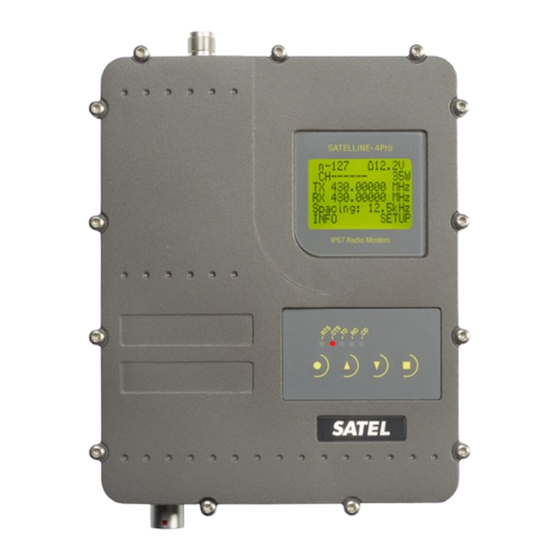
Page 18: Satelline-4Pro Lcd-Display After Power-Up
SATELLINE-4Pro User Guide v1.2 5.2.1 SATELLINE-4Pro LCD-display after power-up The display shows the basic information. Display in Data Transfer Mode (transmit/receive mode) -120: Received signal strength of last received data or noise level (indicated with “ ”) -120 12.2V 12.2 = Supply voltage level indicator. - Page 19 SATELLINE-4Pro User Guide v1.2 Display in Setup Mode > The cursor indicates active line Exit Select Keypad buttons Cancel/Back Select Down...
-
Page 20: Connection Interfaces
SATELLINE-4Pro User Guide v1.2 6 CONNECTION INTERFACES NOTE! When installing the cables of the serial interface, it is recommended that the operating voltage of all devices is powered OFF. 6.1 RS-232 interface RS-232 standard defines the method of serial data transfer between a computer and its peripherals. - Page 21 SATELLINE-4Pro User Guide v1.2 Power connector (4 pin ODU MINI-SNAP Style G4 size 1) NAME EXPLANATION PWR (+) Operation Voltage +9 … +16 VDC Note** PWR (+) Operation Voltage +9 … +16 VDC Note** Ground Note*** Ground Note*** Note**) Both PWR pins 1&2 must be connected!
-
Page 22: Rf Interface
The setting and/or using of non-approved power levels may lead to prosecution. SATEL and its distributors are not responsible for any illegal use of its radio equipment, and are not responsible in any way of any claims or penalties arising from the operation... -
Page 23: Receiver
7.3 Priority RX/TX SATELLINE-4Pro offers a Priority setting, which selects the priority between reception and transmission. The setting can be changed via Configuration Manager PC-program. By default, transmission has higher priority than reception i.e. the default value is Priority TX. -
Page 24: Forward Error Correction
Manager PC-program (or via LCD UI when channel list defined). When activated, the FEC-function will cause the SATELLINE-4Pro to automatically add additional error correction information, which increases the amount of transmitted data by 30 %. It is used by the receiving radio modem to correct erroneous bits - as long as the ratio of correct and erroneous bits is reasonable. -
Page 25: User Data Whitening
7.8 Pacific Crest, TRIMTALK and SOUTH compatibility 7.8.1 General SATELLINE-4Pro radio modem supports additional to the original SATEL 3AS data transfer also: Pacific Crest compatible data transfer over the air, if the opponent Pacific Crest modems operate in the transparent mode/FEC ON/Scrambling ON that is the most common setup among RTK applications. -
Page 26: Configuration By Using Sl Commands
The modem responds with “OK” message if the requested mode is supported or “ERROR” if the mode is not allowed. “SL@S? enquires the active mode. The modem responds with a number: “0” if the mode is SATEL 3AS “1” if the mode is PCC-4FSK “2” if the mode is PCC-GMSK ... - Page 27 RX1 address matches the Remote Address of a Pacific Crest transmitter (or if the message has the broadcast address 255). SATELLINE modems must have the following key settings: FEC OFF (because the FEC here means SATEL 3AS FEC, not Pacific Crest/TRIMTALK FEC) Error check OFF Full CRC16 check OFF ...
- Page 28 Radio Link:Digisquelch Signal threshold Radio Link:Forward Error Correction ON by default using Option 1, 2, 3 (Note: SATELLINE-4Pro FEC must be OFF!) Radio Link:Local Address (0 by default) Primary RX address (RX1) (OFF by default) Radio Link:Remote Address (255 by...
-
Page 29: Repeater Function
Pacific Crest PDL modems. Note 2. If error correction is ON (FEC ON) and TRIMTALK mode is activated by using ”SL@S=3” command, the firmware automatically switches SATEL FEC OFF temporarily, and turns it back at the mode return. 7.8.5 Support for Local / Remote addresses If the modem has TX address ON then primary TX address is handled in the same way as Remote address in Pacific Crest PDL modems. -
Page 30: Latency
SATELLINE-4Pro User Guide v1.2 7.8.6 Latency In the PCC Transparent protocol mode (Option 1 and Option 2) the whole message is first read from the serial port and after that it will be framed and transmitted over the radio. The end of the message is detected when there is a pause in data coming from the serial port. -
Page 31: Transparent Data Transmission
8 TRANSPARENT DATA TRANSMISSION 8.1 Serial interface, data format The SATELLINE-4Pro serial interface uses an asynchronous data format. No external synchronising signal is needed, since necessary timing information is acquired from the start and stop bits transmitted before and after each data field bits (byte). -
Page 32: Cts-Line
SATELLINE-4Pro User Guide v1.2 Handshaking is not needed if the system protocol is designed to prevent collisions (data contention) by the use of polling, or if there is little traffic and also if there is no harm from occasional data contention situations (several radio modems try to transmit at the same time). -
Page 33: Data Buffering In The Radio Data Modem
In order to match the operation of the radio modem to the user data, the Pause length parameter can be adjusted via SATEL Configuration Manager PC-program. It may have any value between 3 and 255 characters. The default value is 3 characters. -
Page 34: Tx Delay
SATELLINE-4Pro User Guide v1.2 The maximum absolute time is always 170 ms independent from the value of the Pause length given in the set-up. An increase in the Pause length increases the round trip delay of the radio link correspondingly;... - Page 35 SATELLINE-4Pro User Guide v1.2 Example of a long data blocks: 00 This is a long testline of SATELLINE-3AS radio modem The strength of the received signal can be monitored using the LCD-display of the receiving radio modem. NOTE 1! Test mode –setting is not indicated in the radio with current implementation.
-
Page 36: Settings
User Guide v1.2 9 SETTINGS SATELLINE-4Pro contains push buttons and a LCD-display, which can be used to modify the pre- defined channel lists, created with SATEL Configuration Manager PC-program. Setting the channel list into use with channel list information is required before the device can be used. Additional information regarding the Configuration Manager can be found from the SW user manual. -
Page 37: Viewing The Set Channel List -Settings
SATELLINE-4Pro User Guide v1.2 After pressing the ”SET-UP-button the display will show the main menu, which is a list of modifiable parameters. Pressing the ▲▼ buttons the cursor moves upwards and downwards. When the cursor is placed beside the desired selection, entry into sub-menu is done by pressing the SELECT- ▲▼... -
Page 38: Lcd Ui Info
SATELLINE-4Pro User Guide v1.2 9.1.1 LCD UI Info After pressing the INFO -button the display will show the current, in use channel settings. ▼ Pressing the ▲▼ buttons the device info can be viewed. ▲▼ ▲▼ ▲ ▲... -
Page 39: Saving Modified Values Into The Internal Memory
When the power of a radio modem is switched off the configuration settings of a radio modem always return to values defined initially using the SATEL Configuration Manager PC-program, thus resetting any settings changed using SL-commands during power on. It is however possible to save settings changed by using SL-commands and to make them the new configuration settings. -
Page 40: Frequency
User Guide v1.2 In case you need more information on the time delays related to the use of SL-commands, please contact the manufacturer. In order to get information of the latest and/or special SL-commands please contact SATEL Oy. 9.2.1 Frequency Command Effect and description of command SL&FR=nnn.nnnnn Set RX-frequency to nnn.nnnnn MHz... -
Page 41: Addressing
SATELLINE-4Pro User Guide v1.2 9.2.2 Addressing xxxx = address in hexadecimal format (0000 … FFFF) Command Effect and description of command SL#I=xxxx Set all addresses (RX1, RX2, TX1, TX2) to value xxxx SL#I? Get both primary addresses (TX1, RX1) (response ’xxxx;yyyy’) -
Page 42: Other Functions
Get modem serial number (response ‘nnnnnnnnnn’ or ‘No Serial nr’) SL%C? Get specified information field. If not specified the response is ‘No version id’). For more information please contact SATEL Oy. SL%B? Get serial data parameters, response is a,b,c,d where a= “115200”, “57600”, "38400", "19200", "9600"... -
Page 43: Repeater Mode And Addressing
SATEL Configuration Manager PC-program or via the LCD UI (when channel list defined to the device via SATEL Configuration Manager PC-program ) . In the repeater mode the radio modem will function as a totally independent unit, which means that only a power supply and a suitable antenna are needed. -
Page 44: Addressing
In case of setting the “Message Routing” function in use, Tx / Rx addresses are ignored by the modem. SATELLINE-4Pro allows the use of individual addresses both for reception and transmission. Addresses can be switched on separately, or simultaneously, in both data transfer directions. - Page 45 SATELLINE-4Pro User Guide v1.2 Transmission: Transmission address has been set OFF. Transmission addressing has been set ON. Radio modem will transmit the data The radio modem will add the primary TX packet as such. address to the beginning of the data packet.
-
Page 46: Connection Between Two Points
SATELLINE-4Pro User Guide v1.2 Reception addressing has Reception addressing Reception addressing been set OFF. been set OFF. been set ON but there is no address in the data packet. The radio modem will radio modem will Data will appear on the RS-... -
Page 47: Using Repeaters And Addresses In The Same System
SATELLINE-4Pro User Guide v1.2 For example, if the substation terminal devices are not able to check and form addresses by themselves, addressing may be achieved with the help of the addresses of the radio modems attached to these terminal devices. The base station may, in such a case, define the destination of a message by adding the address of the corresponding radio modem into the beginning of the data packet. -
Page 48: Repeater Chain Using Address Pairs
SATELLINE-4Pro User Guide v1.2 S ADD DATA - The above is the same message after being relayed from the last repeater in the chain (repeater 2) to the substation. DATA - The above is the same message being relayed via the serial interface of the substation radio modem to the terminal device. -
Page 49: Repeater Chain Using Dual Addressing
SATELLINE-4Pro User Guide v1.2 10.3.3 Repeater chain using dual addressing If the terminal devices cannot add address chains to the beginning of the data packets, a network with several repeaters may still be realised by using dual addressing. In dual addressing each link (see arrows below in figure) is given a unique address, which will prevent duplication of messages and endless loops in the network. -
Page 50: Installation
Suitable dampening and/or isolation materials should be used in cases where the installation surface will be subjected to vibration. 11.1.1 RS-232 Wiring NOTE! In SATELLINE-4Pro the voltage is limited to 16V. -
Page 51: Fuse
User Guide v1.2 11.1.2 Fuse A proper fuse must be connected in between the radio modem and the power supply. The correct value is 15A for SATELLINE-4Pro. 11.1.3 Power supply The allowed operating voltage is +9 ... +16 V . The radio modem must only be connected to a power supply with an adequate current output (power rating minimum is 120W). -
Page 52: Antenna Installation
SATELLINE-4Pro User Guide v1.2 11.2 Antenna installation NOTE! Because of the great transmission power of SATELLINE-4Pro radio modem, only an external antenna is allowed. A whip-antenna directly connected to the antenna connector must not be used. 11.2.1 Mobile equipment ¼-wave antenna ½-wave antenna... - Page 53 SATELLINE-4Pro User Guide v1.2 Antennas must be installed well away from metallic objects. In the case of small antennas this distance should be at least ½ m. With large antennas the distance should be >5 m and in case of repeater antenna combinations >10 m.
- Page 54 SATEL recommends the use of a band-pass filter with a large Q in the antenna cable of the base station.
- Page 55 User Guide v1.2 Example of an antenna installation: by using amplifying antennas (G=Gain) and by installing the antenna high, long connection distances can be realised using the SATELLINE-4Pro radio modem. G > 1 2 d Bi G > 6 d Bi...
-
Page 56: Designing Systems
Interference caused by other electrical equipment The transmitter power of the SATELLINE-4Pro is 35 W (maximum) and the sensitivity of the receiver better than -114 dBm. Thus in a flat area and in free space with a 1/4 wave antenna (antenna amplification 1dBi) and antenna height of 1 m communication distances of 3 to 4 km can be achieved. -
Page 57: Radio Field Strength
SATELLINE-4Pro User Guide v1.2 12.2 Radio field strength Radio signal strength must be good enough for successful data transfer. Where field strength is above a certain level, the operational results are very good. Below this level, a few dB marginal areas occur in which errors begin to be generated by noise and interference that will eventually lead to loss of connection. -
Page 58: Check List
SATELLINE-4Pro User Guide v1.2 13 CHECK LIST The following points must be taken into account when installing and configuring a radio modem: 1. All operating voltages of all the equipment concerned must always be switched OFF before connecting the serial interface cable. -
Page 59: Accessories
2 m cable, ODU 8-pin (0 deg) / ODU 8-pin male (30 deg) YC0240 NARS-ST ODU 8-pin / D15 female Contact SATEL Oy for more detailed information about other serial interface cable options. 14.2 Power cables and supply Type Description... -
Page 60: Antennas
Directional yagi, 8 dBi, 405-440 MHz CA450Y+ Directional yagi, 8 dBi, 440-475 MHz Satel antenna selection includes also directional and/or omni-directional antenna. These can be supplied separately on request. 14.5 Filters and lightning protectors If a radio modem system is installed in an environment that contains high-power transmitters or sources of radio frequency interference, it is highly recommendable to insert suitable filters between each radio modem and its antenna. - Page 61 SATELLINE-4Pro User Guide v1.2 15 APPENDIX A ASCII CHARACTER TABLE NUL 43 2B 129 81 172 AC 215 D7 SOH 44 2C W 130 82 173 AD 216 D8 STX 45 2D 131 83 174 AE 217 D9 ETX 46 2E...
-
Page 62: Functional Delays
SATELLINE-4Pro User Guide v1.2 16 APPENDIX B 16.1 Functional delays Function Delay (ms) Wakeup time from Power OFF -> Power ON 123 ms/typical (=ready to receive) Serial interface, turnaround time of RS-232 RD - TD turnaround wait, if RX freq. -
Page 63: Transmission Delays When The Radio Tx Frequency Is Changed
SATELLINE-4Pro User Guide v1.2 16.2.1 Transmission delays when the radio TX frequency is changed If the modem’s transmitter frequency (TX) is different than the receiver frequency (RX), there has to be at least 40 ms delay from the Receive Data (RD) to Transmit Data (TD). - Page 64 SATELLINE-4Pro User Guide v1.2 Transmission delays with FEC-function (Forward Error Correction). Number of bytes sent 1200 4800 9600 19200 38400 Delays are in milliseconds and with a 10% margin. 12.5 kHz radio channel with error correction 1200 4800 9600 19200...
-
Page 65: Transmission Delays Using A 25 Khz Radio Channel
SATELLINE-4Pro User Guide v1.2 16.2.3 Transmission delays using a 25 kHz radio channel Transmission delays without FEC-function (Forward Error Correction). Number of bytes sent 1200 4800 9600 19200 38400 Delays are in milliseconds and with a 10% marginal. 25 kHz radio channel without error correction... - Page 66 SATELLINE-4Pro User Guide v1.2 Transmission delays with FEC-function (Forward Error Correction). Number of bytes sent 1200 4800 9600 19200 38400 Delays are in milliseconds and with a 10% margin. 25 kHz radio channel with error correction 1200 4800 9600 19200...
Need help?
Do you have a question about the SATELLINE-4Pro and is the answer not in the manual?
Questions and answers