Advertisement
Wiring the Communicator to
the Alarm Panel
Red (+):
12-15V DC Power Supply
Black (-):
Ground
Green (R):
RING
Yellow (T):
TIP
Keyswitch Wiring*
Orange (O):
to Keyswitch zone
White (W):
to Armed status output
Keybus Wiring*
Honeywell Vista and DSC Power Series Panels
Orange (O):
to Yellow (Data Out)
White (W):
to Green (Data In)
Napco Panels
Orange (O):
to TX (Green)
White (W):
to RX (Yellow)
Interlogix NX Panels
Orange (O):
to DATA
White (W):
to DATA
* Optional - wire only if interactive features will be used. Panel compatibility list for Keybus
integration is available at
WARNING: The wiring should be done only when the panel and the
communicator are disconnected from the powerline!
WARNING: PRIMARY USE ONLY – NOT TO BE USED WITH LANDLINE!
Having a phone line connected will damage the unit!
Connect the antenna and place it outside of the alarm panel's box.
Connect + and – of the communicator to a max of 12V - 15V DC power supply.
WARNING: THE USB PORT TO BE USED WITH M2M ADD-ON MODULES ONLY.
Find configuration guides for popular panels at
LED Indicator
Slow flashing – trying to establish connection
Constantly On – connection established at good signal level
Constantly On, blinking every 5 sec. – connection established at low signal level
Fast flashing – transferring data
Configuring the alarm panel
Refer to the panel's installation manual to configure the following options:
Enable the PSTN dialer of the panel.
Select DTMF mode (Tone Dialing).
Select Contact ID Full communication format or SIA.
Enter a telephone number for dialing (you can use any number, e.g. 9999999).
Enter a 4-digit account number in the panel.
Troubleshooting the DTMF communication
If you have issues receiving the events, try the following additional settings of the panel:
Disable "Telephone line monitoring".
Disable "Wait for dial tone" option.
Use "A" instead of "0" in the account number.
If there is more than one partition, enter an account number for each partition.
For certain panels, you might need also to specify an account number for the main partition 0
(sometimes referred as system account number).
v.06-2022-12-02_10000
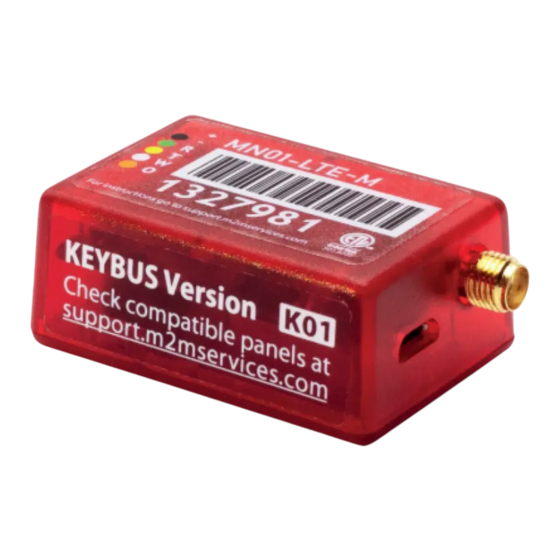
Cellular Communicator with Dial Capture interface
support.m2mservices.com
MN01-LTE-M
Quick Installation Manual
TX (Green)
RX (Yellow)
DATA
White
support.m2mservices.com
Advertisement
Table of Contents

Related Manuals for M2M MN01-LTE-M


Summary of Contents for M2M MN01-LTE-M
- Page 1 Connect + and – of the communicator to a max of 12V - 15V DC power supply. WARNING: THE USB PORT TO BE USED WITH M2M ADD-ON MODULES ONLY. Find configuration guides for popular panels at support.m2mservices.com LED Indicator ...
- Page 2 21 to 28 (21 for partition 1, 22 for partition 2, etc.). The addresses should be reserved for the M2M communicator use only. For Napco panels ONLY: Program a wizzard keypad address on the panel for each partition in use, starting from keypad 2 (21 for partition 1, 22 for partition 2, etc.).
Need help?
Do you have a question about the MN01-LTE-M and is the answer not in the manual?
Questions and answers