Table of Contents

Related Manuals for M2M MQ03-LTE-M-FIRE-AV


Summary of Contents for M2M MQ03-LTE-M-FIRE-AV
- Page 1 MQ03-LTE-M-FIRE-AV Dual-Path/Sole-Path Communicator with Dial Capture Interface Installation and Operations Manual Doc. No. 03004 V 1.4 08/2021 © M2M Services, 1 Kukush Str, building M8, Sofia 1309, Bulgaria www.m2mservices.com...
-
Page 2: Table Of Contents
MQ03-LTE-M-FIRE-AV Installation and Operation Manual Table of Contents About this document ..............................3 Product Description ..............................5 Main Features ................................5 Specifications ................................6 Mounting and Wiring ..............................7 Wiring the Communicator ............................7 Mounting the Communicator ........................... 11 Programming ................................16 Programming the Control Panel .......................... -
Page 3: About This Document
MQ03-LTE-M-FIRE-AV Installation and Operation Manual About this document This document was prepared and wholly owned by M2M Services. It is intended to provide trained personnel with the installation of the MQ03-LTE-M-FIRE-AV. M2M Services reserve the right to edit and revise this manual without notice. - Page 4 Client shall have no claim against M2M Services for termination of contracts, indemnification, compensation for loss of customers, loss of profits, prospective profits, distribution rights, market share, goodwill, investments made or any similar losses that may result from any faults in the operation of the Device and the services provided by M2M Services.
-
Page 5: Product Description
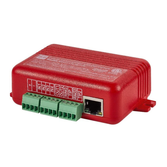
MQ03-LTE-M-FIRE-AV Installation and Operation Manual Product Description The MQ03-LTE-M-FIRE-AV is a digital cellular communicator with dial capture interface. It represents the latest communication technology for the security industry. The communicator is equipped with dual-SIM. In the US one of the SIM cards supports AT&T and the other supports Verizon. -
Page 6: Specifications
MQ03-LTE-M-FIRE-AV Installation and Operation Manual Specifications Characteristics Technical Specifications Supply Voltage +12 to +29 VDC Consumption Standby 60 mA Peak 200 mA Frequency LTE CAT-M1 700/850/1700/1900/2100 MHz GSM Providers AT&T, Verizon, or other available networks in the area Dimensions 2.48”x3.54”x1.26”... -
Page 7: Mounting And Wiring
MQ03-LTE-M-FIRE-AV Installation and Operation Manual Mounting and Wiring Recommended location and wiring methods must be in accordance with the National Electrical code, ANSI/NFPA 72. ▪ Installation must be in accordance with the National Fire Alarm and Signaling Code, NFPA 72. - Page 8 MQ03-LTE-M-FIRE-AV Installation and Operation Manual Wiring for FACP Relay Trigger Input Reporting Figure 2: Wiring Diagram Connect this terminal to AUX + of the panel. Connect this terminal to the AUX – (GND) of the panel. Connect this terminal to a Trouble Relay Output.
- Page 9 Connect this terminal to a Supervision Alarm Relay Output. Note: RING, TIP, RING2, TIP2, OUT1, OUT2 – not required when using the FACP relays *To use this feature, you must enable it in the M2M Administrative Platform -> Device Dashboard menu or via the RControl Admin mobile application.
- Page 10 Connect this terminal to the R1 of the backup dialer of the panel. Connect this terminal to the T1 of the backup dialer of the panel. *To use this feature, you must enable it in the M2M Administrative Platform -> Device Dashboard menu or via the RControl Admin mobile application.
-
Page 11: Mounting The Communicator
Connect this terminal to the AUX – (GND) of the panel. OUT1 Connect this terminal to the Trouble Input of the panel. *To use this feature, you must enable it in the M2M Administrative Platform -> Device Dashboard menu or via the M2M Administrative Mobile Application Mounting the Communicator This communicator comes fully assembled with all the components mounted, except for the external antenna. - Page 12 MQ03-LTE-M-FIRE-AV Installation and Operation Manual Figure 6: MQ03-LTE-M-FIRE mounting in Altronix BC300R Enclosure Proprietary Content, v.1.4 08/2021 © M2M Services 2021...
- Page 13 MQ03-LTE-M-FIRE-AV Installation and Operation Manual Figure 7: MQ03-LTE-M-FIRE-AV mounting in FC08 Enclosure There are several steps in installing MQ03-LTE-M-FIRE-AV properly. In the following steps you will use the communicator and the RControl Admin application to determine the signal strength to find a suitable mounting location.
- Page 14 Note: Antenna problems are rare unless the premises are in an area with poor network coverage, in a building below ground, or in a metal structure. If you require antenna with a longer cable, please contact your M2M Services representative.
- Page 15 7. Login with the end user credentials found in the quick installation manual provided with the device. For more details refer to M2M Smartphone Application Overview V 2.0 at support.m2mservices.com 8. If the signal is low, reposition the antenna and try again to find a better signal. To be verified by the installer.
-
Page 16: Programming
✓ Enter a telephone number for dialing (you can use any number, e.g., 999999) ✓ Enter a 4-digit account number. *Pulse 4/2 reporting requires additional configuration in the M2M Administrative platform Programming guides and a list of the compatible alarm panels are available at http://support.m2mservices.com/...
Need help?
Do you have a question about the MQ03-LTE-M-FIRE-AV and is the answer not in the manual?
Questions and answers