Advertisement
Available languages
Available languages
Quick Links
INSTALLATION INSTRUCTIONS
RAK190V
...........................................5
...................................14
................................... 15
..................................... 17
31-5000842 Rev. 0 09-23
..............................2
.......................10
....................... 15
............................ 18
Advertisement
Chapters

Related Manuals for GE RAK190V


Summary of Contents for GE RAK190V
-
Page 1: Table Of Contents
INSTALLATION INSTRUCTIONS RAK190V SPECIFICATIONS ......2 INSTALLATION INSTRUCTIONS ...........5 WIRING .......10 INSTALLER MENU USING THE THERMOSTAT ........14 OVERVIEW TROUBLESHOOTING ....... 15 ........15 RESETTING WARRANTY ........17 FCC STATEMENT ......18 31-5000842 Rev. 0 09-23... -
Page 2: Specifications
NOTE: Two stage heating = 1st stage heat pump and 2nd stage resistance heat Two Stage Cooling, Three Stage Heating NOTE: Three stage heating = 2 stage heat pump and 3rd stage resistance heat 2-Way Communication with select GE Appliance products 31-5000842 Rev. 0... - Page 3 INSTALLATION INSTRUCTIONS WARNING ELECTRICAL SHOCK HAZARD — Turn off power by unplugging the unit or by removing the fuse or switching the appropriate circuit breaker to the OFF position before removing the existing thermostat. Failure to do so could result in risk of electric shock. PACKAGE CONTENTS/TOOLS REQUIRED: Package includes: •...
-
Page 4: Installation Instructions
INSTALLATION INSTRUCTIONS TO INSTALL THERMOSTAT IMPORTANT: Thermostat installation must conform to local and national building and electrical codes and ordinances. NOTE: Mount the thermostat about five feet above the floor. Do not mount the thermostat on an outside wall, in direct sunlight, behind a door or in an area affected by a vent or duct. -
Page 5: Wiring
INSTALLATION INSTRUCTIONS WIRING Refer to equipment manufacturer’s instructions for specific system wiring information. After wiring, see INSTALLER MENU for proper thermostat configuration. Wiring table shown are for typical systems and describe the thermostat terminal functions. Precautions • Do not exceed the specification ratings. •... - Page 6 INSTALLATION INSTRUCTIONS Diagram 1: 2-Way Communication Wiring (5 Wire) Note: 2-way communication provides 2-way capable equipment with temperature & humidity data to optimize performance. A link icon (see page 14) will be displayed on the thermostat when a successful 2-way connection has been made.
- Page 7 INSTALLATION INSTRUCTIONS Diagram 2: Standard Communication Wiring (3 Heat / 2 Cool), Factory Default Aux Heat Compressor Reversing Valve High Fan Low Fan Stage Compressor 24V AC Common 31-5000842 Rev. 0...
- Page 8 INSTALLATION INSTRUCTIONS Diagram 3: Standard Communication Wiring (2 Heat / 1 Cool) Note: With single stage compressor configuration, Y2 can be used as an occupancy out signal to control make-up air delivery based on occupancy (if needed) Aux Heat Compressor Reversing Valve High Fan Low Fan...
- Page 9 INSTALLATION INSTRUCTIONS Diagram 4: Standard Communication Wiring (1 Heat / 1 Cool) Note: With single stage compressor configuration, Y2 can be used as an occupancy out signal to control make-up air delivery based on occupancy (if needed) Aux Heat Compressor High Fan Low Fan Op onal: Occ Out...
-
Page 10: Installer Menu
INSTALLATION INSTRUCTIONS INSTALLER MENU To access the INSTALLER MENU, use the Power button to turn the thermostat OFF. While OFF, press and hold the Mode and + button for 2 seconds until “Setup Mode” is shown on the display. Once in the menu: •... - Page 11 INSTALLATION INSTRUCTIONS INSTALLER MENU (cont) Menu Item Range/ 8 Wire 2- Way (Mode advances Default Selections Description Setting Setting to next, Fan Setting (+ or - to returns to Availability Availability change) previous) Units (F=Fahrenheit or C= F, C Celsius) Set Current Hours (military time) 0 to 23...
- Page 12 INSTALLATION INSTRUCTIONS INSTALLER MENU (cont) Menu Item Range/ 8 Wire 2- Way (Mode advances Default Selections Description Setting Setting to next, Fan Setting (+ or - to returns to Availability Availability change) previous) Deadband (F) This offset is added to both Cooling &...
- Page 13 INSTALLATION INSTRUCTIONS INSTALLER MENU (cont) Menu Item Range/ 8 Wire 2- Way (Mode advances Default Selections Description Setting Setting to next, Fan Setting (+ or - to returns to Availability Availability change) previous) Occupancy Status Timer (in minutes) The number of minutes occupancy status is maintained 0-99(100) once an occupancy event...
-
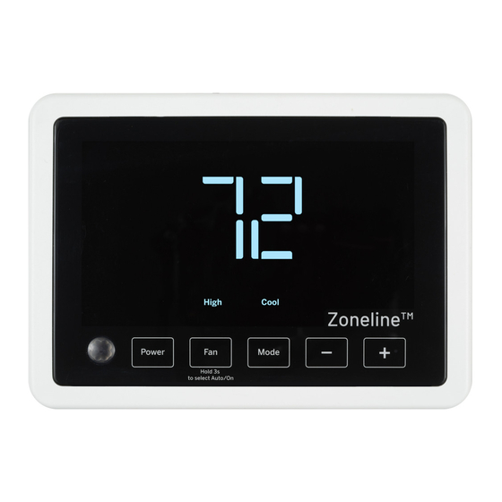
Page 14: Using The Thermostat
USING THE THERMOSTAT THERMOSTAT OVERVIEW Before you begin using your thermostat, you should be familiar with its features, display and the location/operation of the thermostat buttons. THERMOSTAT BUTTONS AND SWITCHES THE DISPLAY 1.) Power 6.) Selected Setpoint 2.) Fan Selection 7.) 2-Way Communication Indicator –... -
Page 15: Troubleshooting
TROUBLESHOOTING Problem Solution No Display Press power button to ensure thermostat isn’t off. Check for 24 VAC; display is blank when 24 VAC is not present System fan does not Verify that wiring is correct. come on properly All thermostat buttons Verify that 24 VAC is present;... - Page 16 NOTES 31-5000842 Rev. 0...
-
Page 17: Warranty
For Warranty replacement, contact your distributor. What GE Appliances Will Not Cover: Service trips to your location. Improper installation. If you have an installation problem, contact your installer. You are responsible for providing adequate electrical connections to the product. -
Page 18: Fcc Statement
FCC STATEMENT NOTE: This equipment has been tested and found to comply with the limits for a Class B digital device, pursuant to part 15 of the FCC Rules. These limits are designed to provide reasonable protection against harmful interference in a residential installation. - Page 19 INSTRUCTIONS D’INSTALLATION RAK190V SPÉCIFICATIONS ......2 INSTALLATION DU THERMOSTAT ........5 CÂBLAGE ..10 MENU DE L’INSTALLATEUR UTILISATION DU THERMOSTAT ..14 APERÇU DU THERMOSTAT DÉPANNAGE ........15 ....... 15 RÉINITIALISATION GARANTIE : ........17 DÉCLARATION DE LA FCC : ... 18 31-5000842 Rev. 0 09-23...
-
Page 20: Spécifications
2e étage par résistance. Refroidissement à deux étages, chauffage à trois étages Remarque : Chauffage à trois étages = thermopompe à 2 étages et chauffage par résistance au 3e étage Communication à 2 voies avec certains produits GE Appliance 31-5000842 Rev. 0... -
Page 21: Installation Du Thermostat
INSTALLATION DU THERMOSTAT AVERTISSEMENT RISQUE D’ÉLECTROCUTION — Coupez l’alimentation en débranchant l’appareil ou en retirant le fusible ou mettant le disjoncteur approprié à la position OFF (hors tension) avant de retirer le thermostat. L’omission de procéder ainsi peut occasionner un choc électrique. Contenu de l’emballage Couvercle du thermostat Thermostat... - Page 22 INSTALLATION DU THERMOSTAT INSTALLATION DU THERMOSTAT IMPORTANT: L’installation de ce thermostat doit être conforme à tous les codes et tous les règlements des Codes du bâtiment et de l’électricité locaux et nationaux. REMARQUE: Montez le thermostat à une hauteur d’environ 1,5 m (5 pi) au-dessus du plancher.
-
Page 23: Câblage
INSTALLATION DU THERMOSTAT CÂBLAGE Consultez le mode d’emploi du fabricant de l’appareil pour les informations spécifiques au câblage du système. Après le câblage, consultez la section MENU DE L’INSTALLATEUR pour configurer correctement le thermostat. Les schémas de câblage illustrés correspondent aux systèmes typiques, et ils décrivent les fonctions des bornes du thermostat. - Page 24 INSTALLATION DU THERMOSTAT Diagramme 1 : Câblage de communication à 2 voies (5 fils) Remarque : La communication à 2 voies fournit un équipement à 2 voies avec des données de température et d’humidité pour optimiser les performances. Une icône de lien (voir page 14) s’affiche sur le thermostat lorsqu’une connexion à...
- Page 25 INSTALLATION DU THERMOSTAT Diagramme 2 : Câblage de communication standard (chaleur : 3 / froid : 2), réglage par défaut en usine Chauffage auxiliaire Aux Heat Compressor Compresseur Reversing Valve Valeur réversible High Fan Vitesse de ventilateur haute Low Fan Vitesse de ventilateur basse Compresseur de 2e étage Stage Compressor...
- Page 26 INSTALLATION DU THERMOSTAT Diagramme 3 : Câblage de communication standard (chaleur : 2 / froid : 1) Remarque : Avec une configuration de compresseur à un étage, Y2 peut être utilisé comme signal de sortie d'occupation pour contrôler l'alimentation en air d'appoint en fonction de l'occupation (si nécessaire) Aux Heat...
- Page 27 INSTALLATION DU THERMOSTAT Diagramme 4 : Câblage de communication standard (chaleur : 1 / froid : 1) Remarque : Avec une configuration de compresseur à un étage, Y2 peut être utilisé comme signal de sortie d'occupation pour contrôler l'alimentation en air d'appoint en fonction de l'occupation (si nécessaire) Aux Heat...
-
Page 28: Menu De L'installateur
INSTALLATION DU THERMOSTAT MENU DE L’INSTALLATEUR Pour accéder au MENU DE L’INSTALLATEUR, utilisez le bouton Power (mise sous/hors tension) pour éteindre le thermostat. Une fois le thermostat éteint, maintenez le bouton Mode enfoncé durant 2 secondes jusqu’à ce que « Setup Mode » apparaisse sur l’écran. Une fois dans le menu : •... - Page 29 INSTALLATION DU THERMOSTAT MENU DE L’INSTALLATEUR (cont) Élément de Plage/ Réglage menu Disponibilité Disponibilité sélections (le mode passe Description de 8 fils de 2 voies au suivant, le (+ ou - pour défaut ventilateur revient changer) au précédent) Unités (F=Fahrenheit ou F, C C= Celsius) Réglage des heures...
- Page 30 INSTALLATION DU THERMOSTAT MENU DE L’INSTALLATEUR (cont) Élément de Plage/ Réglage menu sélections Disponibilité Disponibilité (le mode passe Description de 8 fils de 2 voies au suivant, le (+ ou - pour défaut ventilateur revient changer) au précédent) Zone morte (F) Ce décalage est ajouté...
- Page 31 INSTALLATION DU THERMOSTAT MENU DE L’INSTALLATEUR (cont) Élément de Plage/ Réglage menu Disponibilité Disponibilité sélections (le mode passe Description de 8 fils de 2 voies au suivant, le (+ ou - pour défaut ventilateur revient changer) au précédent) Temporisateur d'état d'occupation (en minutes) Le nombre de minutes pendant lequel l'état d'occupation est...
-
Page 32: Utilisation Du Thermostat
UTILISATION DU THERMOSTAT APERÇU DU THERMOSTAT Avant d’utiliser le thermostat, vous devriez être familier avec ses fonctions, son affichage et l’emplacement/le fonctionnement des boutons. BOUTONS ET SÉLECTEURS AFFICHAGE DU THERMOSTAT 1.) Mise sous/hors tension 6.) Point de consigne sélectionné 2.) Sélection du ventilateur 7.) Indicateur de communication à... -
Page 33: Dépannage
DÉPANNAGE Problème Solution Aucun affichage Appuyez sur le bouton Power pour vous assurer que le thermostat n'est pas éteint. Assurez-vous que la tension est de 24 VAC; l’afficheur ne fonctionnera pas sans cette tension. Le système de ventilation Vérifiez le bon état du câblage ne se met pas en marche correctement Aucun bouton du thermostat... - Page 34 REMARQUE 31-5000842 Rev. 0...
-
Page 35: Garantie
Pour le remplacement sous garantie, contactez votre distributeur. Ce que GE Appliances ne couvre pas : Frais de déplacement pour réparation vers votre emplacement. Une installation mal effectuée. Si vous avez un problème d’installation, communiquez avec votre installateur. -
Page 36: Déclaration De La Fcc
DÉCLARATION DE LA FCC REMARQUE : Cet équipement a été testé et déclaré conforme aux limites d’un dispositif numérique de Classe B, conformément à la partie 15 des règles de la FCC. Ces limites sont définies afin d’assurer une protection raisonnable contre le brouillage nuisible dans une installation résidentielle.
Need help?
Do you have a question about the RAK190V and is the answer not in the manual?
Questions and answers